EP1003296A2 - Verfahren und System zur Basistationsleistungsregelung mit Fähigkeit zur sanften Durchfürung der Weiterreichen - Google Patents
Verfahren und System zur Basistationsleistungsregelung mit Fähigkeit zur sanften Durchfürung der Weiterreichen Download PDFInfo
- Publication number
- EP1003296A2 EP1003296A2 EP99122874A EP99122874A EP1003296A2 EP 1003296 A2 EP1003296 A2 EP 1003296A2 EP 99122874 A EP99122874 A EP 99122874A EP 99122874 A EP99122874 A EP 99122874A EP 1003296 A2 EP1003296 A2 EP 1003296A2
- Authority
- EP
- European Patent Office
- Prior art keywords
- base station
- control signal
- radio communication
- amplitude
- retransmission number
- Prior art date
- Legal status (The legal status is an assumption and is not a legal conclusion. Google has not performed a legal analysis and makes no representation as to the accuracy of the status listed.)
- Withdrawn
Links
Images




Classifications
-
- H—ELECTRICITY
- H04—ELECTRIC COMMUNICATION TECHNIQUE
- H04W—WIRELESS COMMUNICATION NETWORKS
- H04W52/00—Power management, e.g. Transmission Power Control [TPC] or power classes
- H04W52/04—Transmission power control [TPC]
- H04W52/38—TPC being performed in particular situations
- H04W52/40—TPC being performed in particular situations during macro-diversity or soft handoff
-
- H—ELECTRICITY
- H04—ELECTRIC COMMUNICATION TECHNIQUE
- H04B—TRANSMISSION
- H04B7/00—Radio transmission systems, i.e. using radiation field
- H04B7/14—Relay systems
- H04B7/15—Active relay systems
- H04B7/155—Ground-based stations
-
- H—ELECTRICITY
- H04—ELECTRIC COMMUNICATION TECHNIQUE
- H04L—TRANSMISSION OF DIGITAL INFORMATION, e.g. TELEGRAPHIC COMMUNICATION
- H04L1/00—Arrangements for detecting or preventing errors in the information received
- H04L1/0001—Systems modifying transmission characteristics according to link quality, e.g. power backoff
-
- H—ELECTRICITY
- H04—ELECTRIC COMMUNICATION TECHNIQUE
- H04W—WIRELESS COMMUNICATION NETWORKS
- H04W52/00—Power management, e.g. Transmission Power Control [TPC] or power classes
- H04W52/04—Transmission power control [TPC]
- H04W52/38—TPC being performed in particular situations
- H04W52/48—TPC being performed in particular situations during retransmission after error or non-acknowledgment
-
- H—ELECTRICITY
- H04—ELECTRIC COMMUNICATION TECHNIQUE
- H04W—WIRELESS COMMUNICATION NETWORKS
- H04W52/00—Power management, e.g. Transmission Power Control [TPC] or power classes
- H04W52/04—Transmission power control [TPC]
- H04W52/06—TPC algorithms
- H04W52/14—Separate analysis of uplink or downlink
- H04W52/143—Downlink power control
Definitions
- This invention relates to a base station radio communication device (will be often be abbreviated to a base station hereinafter) and a method of controlling the base station radio communication device.
- this invention relates to the base station radio communication device which receives a control signal sent from a base station controller to deliver a transmission signal to a mobile terminal.
- CDMA code division multiple access
- such a CDMA system of a cellular type has a radio base station (which will be called a base station radio communication device) and a plurality of mobile terminal communicable with the base station radio communication device within a radio service area of the base station.
- the base station radio communication device has the radio service area.
- a base station controller is located one at a plurality of the service radio areas and is connected to the plurality of the base station radio communication devices.
- each mobile terminal is moved through the radio service areas from one to another.
- the base station radio communication devices must be switched from one to another without interrupting communication with each mobile terminal.
- a handoff operation is executed to switch the base station radio communication devices from one to another under control of the base station controller.
- the base station radio communication devices are switched from one to another in the CDMA system through a soft handoff operation during which each mobile terminal simultaneously communicates with a plurality of the base station radio communication devices.
- Reference 2 Japanese Unexamined Patent Publication No. Hei 8-8817, namely, 8817/1996 (will be referred to as Reference 2) discloses a transmitter which controls radio transmission power by detecting a radio transmission atmosphere from the retransmission number on failure of transmission. No consideration is made at all in Reference 2 about the soft handoff operation.
- a base station radio communication device to which this invention is applicable is for use in combination with a base station controller to receive a control signal from the base station controller and to transmit the control signal as a transmission signal to a mobile terminal.
- the device comprises receiving means for receiving the control signal and transmit power control means for controlling an amplitude of the transmission signal in accordance with a retransmission number that is representative of the number of retransmission times of the control signal.
- a radio communication system comprises a plurality of base station radio communication devices and a base station controller which controls the base station radio communication devices.
- the base station controller comprises control signal supplying means for supplying a control signal to each of the base station radio communication devices.
- Each of the base station radio communication devices is communicable with a mobile terminal within each radio service area determined for each base station radio communication device and comprises receiving means for receiving the control signal and transmit power control means for controlling an amplitude of the transmission signal in accordance with a retransmission number which is representative of the retransmission number of times of the control signal.
- the transmit power control means comprises a retransmission number detector for detecting the retransmission number of the control signal received through the receiving means to produce an amplitude control signal indicative of the amplitude of the control signal and an amplitude control potion for controlling the amplitude of the control signal that is varied in accordance with the amplitude control signal.
- a method is for use in executing handoff in a radio communication system which comprises a mobile terminal and a plurality of base station radio communication devices.
- the method comprises the steps of transmitting, from either one of the base station radio communication stations and the mobile terminal to another one, a control signal determined for the handoff, augmenting the same control signal to produce an augmented control signal when no acknowledgement of the control signal is received, and retransmitting the augmented control signal again from one to another.
- a conventional CDMA system of a cellular type which has two base station radio communication devices which are depicted by 200A and 200B and a mobile terminal 300 and which will be simply referred as first and second base stations hereinafter.
- the mobile terminal 300 is assumed to move towards the second base station 200B and to be gradually remote from the first base station 200A, communicating with the first base station 200A and that an obstacle 400, such as a big building, exists along a route.
- the mobile terminal 300 can measure reception energy of a transmission signal sent from each of the first and the second base stations 200A and 200B, by monitoring pilot channels assigned to each base station 200A and 200B.
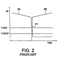
- the reception energy of the pilot channel assigned to the first base station 200A is gradually reduced with time as the mobile terminal 300 is distant from the first base station 200A towards the obstacle 400, as shown by a curve 9A in Fig. 2.
- the reception energy of the pilot channel assigned to the second base station 200B is very low between the first base station 200A and the obstacle 400 on account of shadowing resulting from the obstacle 400, as depicted by a curve 9B in Fig. 2.
- the mobile terminal 300 is communicable only with the first base station 200A. In other words, communication of the mobile terminal 300 is repeated only by the first base station 200A.
- first threshold T-ADD and a second threshold T-DROP are predetermined in connection with the reception energy of each pilot channel. Specifically, when the reception energy exceeds the first threshold T-ADD, the base station in question is added to communicable base stations while the base station is removed or dropped from communicable base stations when its reception energy is less than the second threshold T-DROP.
- the reception energy of the pilot channel assigned to the second base station 200B is abruptly changed, as depicted by the curve 9B in Fig. 2, and exceeds the first threshold T-ADD at a time point P1 in Fig. 2.
- the reception energy of the pilot channel from the first base station 200A is suddenly decreased or attenuated and less than the second threshold T-DROP due to the shadowing resulting from the obstacle 400.
- the reception energy from the second base station 200B brings about interference in a radio signal sent from the first base station and, as a result, make it difficult to communication between the first base station 200A and the mobile terminal 300.
- the mobile terminal 300 transmits a pilot strength measurement report (PSMR) message to the first base station 200A at a step 1.
- PSMR pilot strength measurement report
- the PSMR message is sent through the first base station 200A to the base station controller and is given to the base station controller.
- the base station controller adds the reported base station or stations as new soft handoff candidate stations.
- the second base station 200B is added as the new soft handoff candidate station.
- the base station controller transmits, to the second base station 200B, a traffic channel availability (TCA) message for putting a traffic channel into an active or available state (step S2).
- TCA traffic channel availability
- the second base station 200B which is added as a soft handoff candidate transmits a traffic channel availability acknowledgement (TCA ACK) message to the base station controller at a step 3.
- TCA traffic channel availability acknowledgement
- the base station controller Responsive to the TCA ACK message, the base station controller transmits a handoff direction (HD) message to the mobile terminal 300 through the first base station 200A at a step 4.
- the HD message is indicative of parameters, such as a spread code, which need to communicate with the second base station 200B.
- the HD message must be transmitted to the mobile terminal 300 through the first base station 200A before communication is started between the mobile station 300 and the second base station 200B, in order to smoothly execute the soft handoff.
- the soft handoff procedure is successful.
- the reception energy of the signal sent from the second base station 200B is abruptly increased when the mobile terminal 300 passes the obstacle 400, as shown in Fig. 1B.
- the interference takes place in the radio signal sent from the first base station 200A and, as a result, the mobile terminal 300 can not receive the HD message sent from the first base station 200A.
- the base station controller sends the first base station 200A a traffic channel release message, as shown at a step 5, while the first base station 200A sends a traffic channel release acknowledgement message to the base station controller.
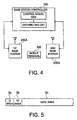
- a cellular CDMA system has a base station controller 100, a plurality of base stations, namely, base station radio communication devices specified by first and second base stations 200A and 200B in Fig. 4, and a plurality of mobile terminals one of which is only depicted by 300 in Fig. 4 for simplification.
- the base station controller 100 is operable as an upper station of the first and the second base stations 200A and 200B to control both of them in a manner to be described later. It may be understood that the illustrated base station controller 100 comprises a control signal generator for generating a control signal as mentioned later and a distributing the control signal to the first and/or the second base stations 200A and 200B.
- the first and the second base stations 200A and 200B have radio service areas or zones.
- the mobile terminal 300 is communicable with the base station controller 100 through the first and the second base stations 200A and 200B within the radio service zones.
- the base station controller 100 supplies the first and the second base stations 200A and 200B with a speech signal and a control signal each of which is produced in the form of a data signal with a signal format.
- the base station controller 100 has a transmitter for transmitting the data signal in addition to a processing circuit for processing each signal given to the base station controller 100.
- the signal format has an identification (ID) area 2a, a retransmission number (RT) area 2b, and a data area 2c.
- the ID area is for arranging an identification signal which serves to distinguish between the speech signal and the control signal while the RT area is for arranging the retransmission number of the data signal located in the ID area.
- the data area is for locating the data signal transmitted to the first and the second base stations 200A and 200B.
- the base station controller 100 In order to detect the number of the retransmission times, the base station controller 100 also has a timer and a counter.
- the timer serves to measure a transmission or a retransmission time of each data signal for a predetermined duration while the counter counts the number of retransmission times, namely, a retransmission number when an indication is given from the timer on lapse of the predetermined duration.
- each data signal is retransmitted each time when the predetermined duration lapses and the number of the retransmission times is located or arranged in the RT area illustrated in Fig. 5.
- the retransmission number is counted only when the control signal is sent from the base station controller 100 to each of the base stations 200.
- the retransmission number is arranged in the retransmission number (RT) area only when the control signal is located in the data area illustrated in Fig. 5.
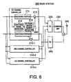
- the illustrated base station 200 has first through n-th channel controllers 210-1 to 210-n, a transmitter (TX) 220, a common amplifier 230, an antenna 240, and a receiver (RX) 250.
- n is an integer not smaller than three.
- the receiver 250 receives a reception signal through the antenna 240 and a hybrid and demodulates the same into a demodulated signal which is decoded into a decoded signal by each of the channel controllers 210-1 to 210-n to be sent to the base station controller 100.
- the transmitter 220 is connected to the first through the n-th channel controllers 210-1 to 210-n and is given coded signals obtained by encoding, in the channel controllers 210-1 to 210-n, a received signal sent from the base station controller 100.
- the coded signals are summed up and modulated by the transmitter 220 to be produced as a modulated signal.
- the modulated signal is amplified by the common amplifier 230 to be transmitted as a radio output signal from the antenna 240.
- the base station 200 has the plurality of the channel controllers 210-1 to 210-n, as shown in Fig. 6. However, since each of the first through the n-th channel controllers 210-1 to 210-n is similar in structure and operation to one another, description will be made only about the first channel controller 210-1 alone.
- the first channel controller 210-1 has an encoding portion 211, a control signal detector 212, an amplitude control portion 213, and a retransmission number detector 215.
- the encoding portion 211 encodes the data signal sent from the base station controller 100 into an encoded signal while the amplitude control portion 213 controls an amplitude of the encoded signal. Consequently, the amplitude control portion 213 serves to control transmission power sent from the base station 200 to the mobile station 300.
- control signal detector 212 is operable to detect whether the data signal from the base station controller 100 detects or identifies the speech signal or the control signal.
- the retransmission number detector 215 counts the retransmission number of the control signal to produce an amplitude control signal AMC determined for the retransmission number in a manner to be described later.
- the amplitude of the encoded signal produced by the amplitude control portion 213 is varied in accordance with the amplitude control signal AMC sent from the retransmission number detector 215.
- the amplitude control portion 213 is controlled so that the amplitude of the encoded signal becomes large with an increase of the retransmission number of the control signal.
- the retransmission number detector 215 has a function of designating an amplitude value to the amplitude control portion 213 by producing the amplitude control signal.
- the speech signal is transmitted from the base station controller 100 to the illustrated base station 200.
- the speech signal is encoded by the encoding portion 211 into the encoded signal and is thereafter sent to the amplitude control portion 213.
- the amplitude control portion 213 controls the amplitude value of the encoded signal in response to the amplitude control signal AMC given from the retransmission number detector 215.
- the speech signal is produced from the amplitude control portion 213 as an amplitude controlled encoded signal.
- the amplitude control portion 213 is set so that the speech signal has a predetermined amplitude. At any rate, the amplitude controlled encoded signal is sent from the amplitude control portion 213 to the transmitter 220 and is modulated by the transmitter 220 into a modulated signal.
- the modulated signal is transmitted as a radio signal through the common amplifier 230 and the antenna 240 to the mobile terminal 300.
- control signal is assumed to be given from the base station controller 100 to the base station 200.
- the control signal is detected by the control signal detector 212 to be sent to the retransmission number detector 215.
- the retransmission number detector 215 detects the retransmission number, namely, retransmission times of the control signal.
- control signal is identified by the ID area 2a of the data signal sent from the base station controller 100.
- a control signal identification code is arranged in the ID area 2a to identity the control signal when the control signal is located within the data area 2c.
- the retransmission number is arranged in the retransmission number (RT) area 2c on transmission of the control signal. If the RT area is arranged with zero as the retransmission number, the retransmission number detector 215 sets the amplitude control portion 213 into an amplitude which is equal to the predetermined amplitude given to the speech signal. On the other hand, when the retransmission number becomes equal to unity, the retransmission number detector 215 sets the amplitude control portion 213 into an amplitude greater than the predetermined amplitude. Likewise, the amplitude set in the amplitude control portion 213 is further augmented under control of the retransmission number detector 215 when the retransmission number becomes equal to two.
- the retransmission number detector 215 sets the amplitude control portion 213 into a square root of 2, namely, ⁇ 2 (about 1.4) times the predetermined amplitude determined for the speech signal, when the retransmission number is equal to unity.
- the transmission number detector 215 is operable to set the amplitude control portion 213 into the amplitude which is augmented with an increase of the retransmission number of the control signal.
- the control signal is delivered to the encoding portion 211 to be encoded into an encoded control signal as the encoded signal and is sent to the amplitude control portion 213.
- the encoded control signal is controlled in its amplitude by the amplitude control portion 213 so as to be augmented to the amplitude indicated by the amplitude control signal (AMC).
- the augmented control signal is sent from the amplitude control portion 213 to the transmitter 220 to be modulated and to be transmitted through the common amplifier 230 and the antenna 240.
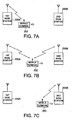
- the cellular CDMA system has a base station controller 100 as illustrated in Fig. 4 and first and second base stations 200A and 200B each of which is similar in structure and operation to that illustrated in Fig. 6. Under the circumstances, it is assumed that the mobile station 300 communicates with the first base station 200A and is moved towards the second base station 200B, as shown in Fig. 7A.
- the reception energy of the pilot channel from the first base station 200A is gradually reduced, as depicted by a curve 80A, as the mobile terminal 300 becomes remote from the first base station 200A.
- the reception energy of the pilot signal from the second base station 200B is gradually increased, as depicted by a curve 80B, as the mobile terminal 300 becomes close to the second base station 200B.
- first and second thresholds T-ADD and T-DROP are determined, as already mentioned in conjunction with Fig. 2.
- T-ADD Transmissions Industry Association
- EIA Electronic Industries Association
- T-DROP Second threshold
- Fig. 8 let the mobile terminal 300 be moved towards the second base station 200B and be close to the second base station 200B, as illustrated in Fig. 7B.
- the reception energy of the pilot channel from the second base station 200B exceeds the first threshold T-ADD at a point P1, as shown by the curve 80B while the reception energy of the pilot channel from the first base station 200A also exceeds the first threshold T-ADD, as shown by the curve 80A.
- the mobile terminal 300 detects that the reception energy from the second base station 200B exceeds the first threshold T-ADD, as shown in Fig. 8. In this case, operation is executed in a manner illustrated in Fig. 9 when the handoff direction (HD) message is not retransmitted while operation is executed in a manner illustrated in Fig. 10 when the HD message is retransmitted from the first base station.
- the handoff direction (HD) message is not retransmitted
- Fig. 10 when the HD message is retransmitted from the first base station.
- the pilot strength measurement report (PSMR) message is transmitted from the mobile terminal 300 to the first base station 200A and is thereafter transferred from the first base station 200A to the base station controller 100, as shown at a step 1 in Fig. 9.
- the PSMR message informs the base station controller of the second base station 200B from which the reception energy of the pilot signal exceeds the first threshold T-ADD.
- the base station controller adds the second base station 200B as a new soft handoff candidate station and sends the second base station 200B a traffic channel availability (abbreviated to TCA) message at a step 2 in Fig. 9.
- TCA traffic channel availability
- Such a TCR message serves to make the second base station 200B start a repeat operation of communication between the mobile terminal 300 and the base station controller. This shows that the second base station 200B is added in the base station controller as the new soft handoff candidate station.
- the second base station 200B Responsive to the TCA message from the base station controller, the second base station 200B returns a traffic channel availability (TCA) acknowledgement (ACK) message back to the base station controller, as shown at a step 3 in Fig. 9.
- TCA traffic channel availability
- ACK acknowledgement
- the base station controller transmits a handoff direction (HD) message to the first base station 200A and, thereafter, the HD message is transferred one time from the first base station 200A to the mobile terminal 300, as shown at a step 4 in Fig. 9.
- the HD message includes parameters, such as spread codes, which need to communicate with the second base station 200B.
- the HD message is given to the control signal detector 212 of the first base station 200A illustrated in Fig. 6.
- the control signal detector 212 judges the HD message signal as the control signal by monitoring the ID area of the HD message.
- the retransmission number of the HD message is detected by the retransmission number detector 215 (Fig. 6) of the first base station 200A.
- the HD message is received by the first base station 200A only one time and the retransmission number is set into zero. Therefore, the retransmission number detector 215 sets the amplitude control portion 213 to the same amplitude value as the speech signal.
- the HD message is transferred from the antenna 240 of the first base station 200A with the same energy as the speech signal.
- the mobile terminal 300 sets the parameters indicated by the HD message and, thereafter, transmits a handoff completion message to the first base station 200A at a step 5.
- the handoff completion message is also transmitted from the mobile terminal 300 to the second base station 200B, as shown at a step 6 in Fig. 9.
- the handoff completion message is received by both or either one of the first and the second base stations 200A and 200B and is thereafter transferred to the base station controller, as shown at the steps 5 and 6.
- the base station controller selects either one of the handoff completion messages that is sent from the first and the second base stations 200A and 200B and that has a high probability.
- the base station controller finishes the addition procedure for the soft handoff and put both the first and the second base stations 200A and 200B into soft handoff states, as shown in Fig. 8 and at a step 7 in Fig. 9.
- communication is executed through both the first and the second base stations 200A and 200B that are operable as repeater stations.
- the mobile terminal 300 does not receives a first one of the HD message sent from the first base station 200A, as illustrated at a step 4 in Fig. 10. In this event, no handoff completion message is transmitted from the mobile terminal 300, as readily understood from Fig. 10.
- the base station controller can not finish the addition procedure for the soft handoff on account of no reception of the handoff completion message. Accordingly, the base station controller transmits the same HD message again through the first base station 200A to the mobile terminal 300 at a step 4-1 in Fig. 10. Such a HD message produced again will be called a second HD message.
- the control signal detector 212 of the first base station 200A judges the second HD message as the control signal. Subsequently, the retransmission number detector 215 is operated to detect the retransmission number of the HD message to be sent to the first base station 200A. In the illustrated example, the retransmission number detector 215 detects that the retransmission number becomes equal to unity, so as to set the amplitude control portion 213 into the amplitude value which is greater than that of the speech signal.
- the second HD message has the amplitude value which is about 1.4 times that of the speech signal and the energy equal to twice that of the speech signal.
- the second HD message is sent through the antenna 240 from the first base station 200A to the mobile terminal 300 again with twice the energy of the speech signal.
- the mobile terminal 300 transmits the PSMR message, as shown in Figs. 9 and 10.
- the PSMR message As shown in Figs. 9 and 10.
- description will be made with reference to only Fig. 9 hereinafter.
- the transmitted PSMR message can be received by the first base station 200A (step 8) and/or the second base station 200B (step 9).
- the base station controller selects either one of the PSMR messages that has a high probability.
- the PSMR message informs the base station controller of the base station, namely, the first base station 200A in which the reception energy of the pilot channel is lower than the second threshold T-DROP.
- the reported base station, namely, the first base station 200A is removed from the soft handoff candidate stations in the base station controller.
- the base station controller Supplied with the PSMR message, the base station controller prepares the HD message indicative of deletion of the first base station 200A from repeater stations and sends the same to the mobile terminal 300 through both the first base station 200A (step 10) and the second base station 200B (step 11).
- the control signal detector 212 of the first base station 200A judges the HD message as the control signal. Thereafter, the retransmission number detector 215 of the first base station 200A detects the retransmission number of the HD message. In the example illustrated in Fig. 9, the retransmission number is set into zero in the retransmission number detector 215 because the HD message in question is transmitted as a first control signal from the base station controller after the soft handoff state. Therefore, the retransmission number detector 215 sets the amplitude control portion 213 into the amplitude value equal to that of the speech signal. The resultant HD message is transmitted from the first base station 200A through the antenna 240 with the same energy as that of the speech signal.
- the retransmission number detector 215 of the first base station 200A sets the amplitude control portion 213 into the amplitude value which is greater than that of the speech signal, like in the addition procedure for the soft handoff.
- the amplitude value of the HD message may be a square root of two, namely, about 1.4 times the amplitude value of the speech signal and the resultant energy of the HD message becomes equal to twice the speech signal.
- the mobile terminal 300 sets the parameters which need to delete the first base station 200A from the repeater stations. Thereafter, the mobile terminal 300 produces the handoff completion message.
- the handoff completion message is sent from the mobile terminal 300 and is received by the first base station 200A (step 12) and/or the second base station 200B (step 13) to be sent to the base station controller.
- the base station controller selects either one of the handoff completion messages that has a high probability.
- the base station controller sends the first base station 200A the traffic channel release message (step 14) to stop the communication between the mobile terminal 300 and the first base station 200A.
- the first base station 200A Responsive to the traffic channel release message, the first base station 200A returns the traffic channel release acknowledgement (ACK) message back to the base station controller, as shown at a step 15 in Fig. 9.
- ACK traffic channel release acknowledgement
- the deletion procedure from the soft handoff is finished and the mobile terminal 300 communicates only with the second base station 200B, as shown at a step 16 in Fig. 9.
- communication between the mobile terminal 300 and the base station controller is executed only through the second base station 200B, as illustrated in Fig. 7C.
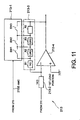
- the amplitude control portion 213 illustrated in Fig. 11 is operable in response to the amplitude control signal sent from the retransmission number detector 215.
- the amplitude control portion 213 has an amplitude setter 213-1, a first load portion 213-2, a second load portion 213-3, and an amplifier 213-4 which may be formed by an operational amplifier having an inverting input terminal (-), a non-inverting input terminal (+), and an output terminal.
- the illustrated amplitude setter 213-1 has first through third switches SW1 to SW3 which are selectively turned on or off in response to the amplitude control signal AMC.
- the first load portion 213-2 is connected to the inverting input terminal of the amplifier 213-4 and to the second load portion 213-3 also, as shown in Fig. 11.
- the illustrated first load portion 213-2 is assumed to have a resistance value of 1 K ⁇ .
- the second load portion 213-3 is formed by first through fourth resistors which are connected in series to one another.
- the first through the third resistors are assumed to have resistance values of 1 K ⁇ , 0.4 K ⁇ , and 0.6 K ⁇ , respectively.
- the amplification factor of the illustrated amplifier 213-4 is determined by a resistance value ratio of the first load portion 213-2 to the second load portion 213-3.
- the first switch SW1 may be turned off while the second and the third switches SW2 and SW3 are turned on. This is because the resistance value of the second load portion 213-3 becomes equal to 1.4 K ⁇ and is 1.4 times the resistor value of the first load portion 213-2.
- the first and the second switches SW1 and SW2 may be put into off states while the third switch SW3 may be put into an on state.
- the resultant resistance value of the second load portion 213-3 becomes equal to 2.0 K ⁇ and, therefore, the amplification factor of the amplifier 213-4 becomes equal to two.
- the amplitude control portion 213 is structured by the second load portion 213-3 formed by the series circuit of the resistors, a switch circuit formed by the first through the third switches SW1 to SW3, and the amplifier 214-4 formed by an inverting amplifier, namely, the operational amplifier to which the second load portion 213-3 is connected as a feedback resistor.
- the first through the third switches SW1 to SW3 are connected across the corresponding resistors in the manner illustrated in Fig. 11 so that each of the corresponding resistors is shortened.
- the first through the third switches SW1 to SW3 are selectively turned on or off in accordance with the retransmission number indicated by the amplitude control signal AMC given from the retransmission number detector 215 (Fig. 6).
- the amplification factor of the amplifier 213-4 can be augmented with an increase of the retransmission number of the control signal.
- each of the first and the second base stations 200A and 200B is featured in that the control signal sent from the base station controller is transmitted as the transmission signal to the mobile terminal in a manner augmented with an increase of the retransmission number.
- the method of transmitting the control signal from each base station includes the step of detecting the retransmission number of the control signal sent from the base station controller and the step of augmenting the amplitude of the transmission signal with the increase of the retransmission number.
- the retransmission number may be included in the control signal sent from the base station controller.
- the control signal is retransmitted from each base station to each base station with augmented or increased power when the control signal is not received by a mobile terminal once.
- Such retransmission of the control signal with the augmented or high power serves to avoid a call drop even when reception energy from another base station is abruptly increased.
- This means that the retransmission of the high power is helpful to prevent the call drop due to interference resulting from another base station.
- this invention is also applicable to a control signal which is sent from each mobile terminal to the base station controller.
- the control signal detector 212, the retransmission number detector 215, and the amplitude control portion 213 illustrated in Fig. 6 may be included in each mobile terminal.
- the speech signal may be augmented together with the control signal in accordance with the retransmission number of the control signal, although the control signal alone is augmented with an increase of the retransmission number in the above-mentioned embodiment.
- the retransmission number of the control signal may be counted within each base station or the mobile terminal without being counted in the base station controller.
- this invention may be applied to a cellular TDMA system without being restricted to the cellular CDMA system.
Landscapes
- Engineering & Computer Science (AREA)
- Computer Networks & Wireless Communication (AREA)
- Signal Processing (AREA)
- Quality & Reliability (AREA)
- Mobile Radio Communication Systems (AREA)
Applications Claiming Priority (2)
| Application Number | Priority Date | Filing Date | Title |
|---|---|---|---|
| JP32738398A JP2000151504A (ja) | 1998-11-18 | 1998-11-18 | 基地局無線装置及びその制御方法 |
| JP32738398 | 1998-11-18 |
Publications (2)
| Publication Number | Publication Date |
|---|---|
| EP1003296A2 true EP1003296A2 (de) | 2000-05-24 |
| EP1003296A3 EP1003296A3 (de) | 2003-03-19 |
Family
ID=18198542
Family Applications (1)
| Application Number | Title | Priority Date | Filing Date |
|---|---|---|---|
| EP19990122874 Withdrawn EP1003296A3 (de) | 1998-11-18 | 1999-11-17 | Verfahren und System zur Basistationsleistungsregelung mit Fähigkeit zur sanften Durchfürung der Weiterreichen |
Country Status (5)
| Country | Link |
|---|---|
| EP (1) | EP1003296A3 (de) |
| JP (1) | JP2000151504A (de) |
| KR (1) | KR100311341B1 (de) |
| CN (1) | CN1188952C (de) |
| BR (1) | BR9907361A (de) |
Cited By (9)
| Publication number | Priority date | Publication date | Assignee | Title |
|---|---|---|---|---|
| WO2002047361A3 (en) * | 2000-12-05 | 2003-10-30 | Qualcomm Inc | Method and apparatus for power level adjustment in a wireless communication system |
| KR100445546B1 (ko) * | 2001-06-12 | 2004-08-25 | 모토로라 인코포레이티드 | 통신 시스템에서 레스큐 채널들을 지원하는 방법 |
| US7263084B2 (en) | 2002-01-17 | 2007-08-28 | Matsushita Electric Industrial Co., Ltd. | Radio transmitting apparatus, radio receiving apparatus and radio transmitting method |
| EP1531569A4 (de) * | 2002-08-23 | 2009-05-13 | Panasonic Corp | Cdma-übertragungseinrichtung und cdma-übertragungsverfahren |
| US7567781B2 (en) | 2001-01-05 | 2009-07-28 | Qualcomm, Incorporated | Method and apparatus for power level adjustment in a wireless communication system |
| US7746762B2 (en) | 2002-11-18 | 2010-06-29 | Panasonic Corporation | Transmitting apparatus and transmitting method |
| CN1667990B (zh) * | 2004-03-10 | 2011-01-05 | 华为技术有限公司 | 一种减少相邻蜂窝小区间干扰的方法 |
| US7945266B2 (en) | 2000-12-05 | 2011-05-17 | Qualcomm Incorporated | Method and apparatus for call recovery in a wireless communication system |
| CN102111818A (zh) * | 2009-12-29 | 2011-06-29 | 中兴通讯股份有限公司 | 一种无线接入网的切换控制方法和接入网 |
Families Citing this family (7)
| Publication number | Priority date | Publication date | Assignee | Title |
|---|---|---|---|---|
| CN100456660C (zh) * | 2000-11-17 | 2009-01-28 | Lg电子株式会社 | 在自动重发请求系统中使用确认的盲型链路适配方法 |
| KR20030060200A (ko) * | 2002-01-07 | 2003-07-16 | 삼성전자주식회사 | 통신 시스템에서 호 연결 실패율을 감소시키는 방법 |
| DE10321207B3 (de) * | 2003-05-12 | 2005-02-17 | Siemens Ag | Verfahren zur Steuerung der Sendeleistung einer sendenden Station eines Funkkommunikationssystems sowie sendende Station, empfangende Station und Funkkomunikationssystem |
| US20110044290A1 (en) * | 2006-04-28 | 2011-02-24 | Panasonic Corporation | Communication terminal apparatus and handover method |
| JP2009089203A (ja) * | 2007-10-02 | 2009-04-23 | Panasonic Corp | 無線装置および無線通信システム |
| CN102027703A (zh) * | 2008-05-15 | 2011-04-20 | 夏普株式会社 | 通信装置、通信系统、接收方法和通信方法 |
| JP5562281B2 (ja) * | 2011-03-24 | 2014-07-30 | 株式会社日立製作所 | 無線通信システム、基地局装置及び無線通信方法 |
Family Cites Families (4)
| Publication number | Priority date | Publication date | Assignee | Title |
|---|---|---|---|---|
| EP0565507A3 (en) * | 1992-04-10 | 1994-11-30 | Ericsson Ge Mobile Communicat | Power control for random access call set-up in a mobile telephone system |
| US5613228A (en) * | 1992-07-06 | 1997-03-18 | Micron Technology, Inc. | Gain adjustment method in two-way communication systems |
| US6088590A (en) * | 1993-11-01 | 2000-07-11 | Omnipoint Corporation | Method and system for mobile controlled handoff and link maintenance in spread spectrum communication |
| US5920550A (en) * | 1996-10-11 | 1999-07-06 | Motorola, Inc. | System, method, and apparatus for soft handoff |
-
1998
- 1998-11-18 JP JP32738398A patent/JP2000151504A/ja active Pending
-
1999
- 1999-11-17 EP EP19990122874 patent/EP1003296A3/de not_active Withdrawn
- 1999-11-17 KR KR1019990051096A patent/KR100311341B1/ko not_active Expired - Fee Related
- 1999-11-18 BR BR9907361A patent/BR9907361A/pt not_active IP Right Cessation
- 1999-11-18 CN CNB991239458A patent/CN1188952C/zh not_active Expired - Fee Related
Cited By (10)
| Publication number | Priority date | Publication date | Assignee | Title |
|---|---|---|---|---|
| WO2002047361A3 (en) * | 2000-12-05 | 2003-10-30 | Qualcomm Inc | Method and apparatus for power level adjustment in a wireless communication system |
| US7945266B2 (en) | 2000-12-05 | 2011-05-17 | Qualcomm Incorporated | Method and apparatus for call recovery in a wireless communication system |
| US7567781B2 (en) | 2001-01-05 | 2009-07-28 | Qualcomm, Incorporated | Method and apparatus for power level adjustment in a wireless communication system |
| KR100445546B1 (ko) * | 2001-06-12 | 2004-08-25 | 모토로라 인코포레이티드 | 통신 시스템에서 레스큐 채널들을 지원하는 방법 |
| US7263084B2 (en) | 2002-01-17 | 2007-08-28 | Matsushita Electric Industrial Co., Ltd. | Radio transmitting apparatus, radio receiving apparatus and radio transmitting method |
| EP1531569A4 (de) * | 2002-08-23 | 2009-05-13 | Panasonic Corp | Cdma-übertragungseinrichtung und cdma-übertragungsverfahren |
| US7729390B2 (en) | 2002-08-23 | 2010-06-01 | Panasonic Corporation | Code division multiple access transmitting apparatus having plural spreading sections that perform spreading processing separately for a retransmission signal using different spreading codes |
| US7746762B2 (en) | 2002-11-18 | 2010-06-29 | Panasonic Corporation | Transmitting apparatus and transmitting method |
| CN1667990B (zh) * | 2004-03-10 | 2011-01-05 | 华为技术有限公司 | 一种减少相邻蜂窝小区间干扰的方法 |
| CN102111818A (zh) * | 2009-12-29 | 2011-06-29 | 中兴通讯股份有限公司 | 一种无线接入网的切换控制方法和接入网 |
Also Published As
| Publication number | Publication date |
|---|---|
| JP2000151504A (ja) | 2000-05-30 |
| KR20000035536A (ko) | 2000-06-26 |
| EP1003296A3 (de) | 2003-03-19 |
| BR9907361A (pt) | 2000-10-17 |
| CN1188952C (zh) | 2005-02-09 |
| CN1261224A (zh) | 2000-07-26 |
| KR100311341B1 (ko) | 2001-11-05 |
Similar Documents
| Publication | Publication Date | Title |
|---|---|---|
| US6333921B1 (en) | Method and apparatus for group calls in a wireless CDMA system based on dedicated codes | |
| EP1116407B1 (de) | Verfahren zum stabilen weiterreichen in einem drahtlosen kommunikationssystem | |
| US6256501B1 (en) | Cellular mobile telecommunications system for controlling a hand-off by a mobile station | |
| KR100381831B1 (ko) | 멀티캐스트 통신 시스템 | |
| US5133080A (en) | Repeater for a controlled radio system | |
| KR100311341B1 (ko) | 핸드오프를 서서히 실행할 수 있는 기지국 제어방법 및시스템 | |
| EP0325713A2 (de) | Zellulares Funktelefonsystem mit Schutz gegen Anrufausfälle | |
| UA46827C2 (uk) | Спосіб переведення зв'язку абонентського пристрою у безпровідній системі зв'язку (варіанти), спосіб роботи абонентського пристрою у цій системі та стільникова телефонна система, що забезпечує обслуговування абонентського пристрою | |
| EP0917809A2 (de) | Verfahren und vorrichtung zum zuverlässigen weiterreichen zwischen systemen in einem system mit code-verteilungsmultiplexzugriff | |
| CN1744456B (zh) | 使用功率控制算法改进移动无线通信系统性能的方法 | |
| WO1999023848A2 (en) | Network element monitoring in a radio telecommunication network | |
| EP0590776A1 (de) | Funktelefonsystem mit Leistungsregelung und Zusatzempfängern | |
| RU2003120072A (ru) | Способ и устройство для восстановления вызова в системе беспроводной связи | |
| US20050181794A1 (en) | Apparatus and method for improved handoffs in an EV-DV wireless network | |
| JP2984653B1 (ja) | Cdma方式セルラシステムの基地局無線装置 | |
| EP0406905A2 (de) | Doppelverstärkersystem | |
| US6947735B2 (en) | Method for avoiding interferences in cellular CDMA radio networks caused by defective mobile stations | |
| US6370387B1 (en) | Cellular telecommunication system with macrodiversity mode | |
| KR100367794B1 (ko) | Cdma 기지국 및 cdma 기지국의 통신 제어 방법 | |
| KR20000001177A (ko) | 이동통신 시스템 단말기의 불필요한 핸드오프 요구 메시지 전송방지방법 | |
| EP0930591A1 (de) | Automatische Ortung von Personen unter Verwendung einer Kombination drahtloser Medien | |
| JP2991872B2 (ja) | 無線移動端末 | |
| JPH0984130A (ja) | 移動通信における制御情報の再送方式 | |
| MXPA98010794A (en) | Automatic localization of individuals using the combination of media inalambri | |
| MXPA02002292A (en) | System and method for controlling transmitter power of a narrowband advanced messaging system |
Legal Events
| Date | Code | Title | Description |
|---|---|---|---|
| PUAI | Public reference made under article 153(3) epc to a published international application that has entered the european phase |
Free format text: ORIGINAL CODE: 0009012 |
|
| AK | Designated contracting states |
Kind code of ref document: A2 Designated state(s): AT BE CH CY DE DK ES FI FR GB GR IE IT LI LU MC NL PT SE |
|
| AX | Request for extension of the european patent |
Free format text: AL;LT;LV;MK;RO;SI |
|
| RIC1 | Information provided on ipc code assigned before grant |
Free format text: 7H 04B 7/005 A, 7H 04L 1/18 B |
|
| PUAL | Search report despatched |
Free format text: ORIGINAL CODE: 0009013 |
|
| RIC1 | Information provided on ipc code assigned before grant |
Ipc: 7H 04Q 7/38 B Ipc: 7H 04L 1/18 B Ipc: 7H 04B 7/005 A |
|
| AK | Designated contracting states |
Kind code of ref document: A3 Designated state(s): AT BE CH CY DE DK ES FI FR GB GR IE IT LI LU MC NL PT SE Designated state(s): AT BE CH CY DE DK ES FI FR GB GR IE IT LI LU MC NL PT SE |
|
| AX | Request for extension of the european patent |
Extension state: AL LT LV MK RO SI |
|
| 17P | Request for examination filed |
Effective date: 20030220 |
|
| 17Q | First examination report despatched |
Effective date: 20030618 |
|
| STAA | Information on the status of an ep patent application or granted ep patent |
Free format text: STATUS: THE APPLICATION HAS BEEN WITHDRAWN |
|
| 18W | Application withdrawn |
Effective date: 20030919 |