EP1003321A2 - Integrierte Kammer mit Beleuchtungssystem - Google Patents
Integrierte Kammer mit Beleuchtungssystem Download PDFInfo
- Publication number
- EP1003321A2 EP1003321A2 EP99309213A EP99309213A EP1003321A2 EP 1003321 A2 EP1003321 A2 EP 1003321A2 EP 99309213 A EP99309213 A EP 99309213A EP 99309213 A EP99309213 A EP 99309213A EP 1003321 A2 EP1003321 A2 EP 1003321A2
- Authority
- EP
- European Patent Office
- Prior art keywords
- chamber
- light
- opening
- lamp
- front opening
- Prior art date
- Legal status (The legal status is an assumption and is not a legal conclusion. Google has not performed a legal analysis and makes no representation as to the accuracy of the status listed.)
- Withdrawn
Links
Images

Classifications
-
- H—ELECTRICITY
- H04—ELECTRIC COMMUNICATION TECHNIQUE
- H04N—PICTORIAL COMMUNICATION, e.g. TELEVISION
- H04N1/00—Scanning, transmission or reproduction of documents or the like, e.g. facsimile transmission; Details thereof
- H04N1/024—Details of scanning heads ; Means for illuminating the original
- H04N1/028—Details of scanning heads ; Means for illuminating the original for picture information pick-up
- H04N1/02815—Means for illuminating the original, not specific to a particular type of pick-up head
- H04N1/02845—Means for illuminating the original, not specific to a particular type of pick-up head using an elongated light source, e.g. tubular lamp, LED array
- H04N1/0285—Means for illuminating the original, not specific to a particular type of pick-up head using an elongated light source, e.g. tubular lamp, LED array in combination with at least one reflector which is in fixed relation to the light source
-
- H—ELECTRICITY
- H04—ELECTRIC COMMUNICATION TECHNIQUE
- H04N—PICTORIAL COMMUNICATION, e.g. TELEVISION
- H04N1/00—Scanning, transmission or reproduction of documents or the like, e.g. facsimile transmission; Details thereof
- H04N1/024—Details of scanning heads ; Means for illuminating the original
- H04N1/028—Details of scanning heads ; Means for illuminating the original for picture information pick-up
- H04N1/02815—Means for illuminating the original, not specific to a particular type of pick-up head
- H04N1/02845—Means for illuminating the original, not specific to a particular type of pick-up head using an elongated light source, e.g. tubular lamp, LED array
- H04N1/0287—Means for illuminating the original, not specific to a particular type of pick-up head using an elongated light source, e.g. tubular lamp, LED array using a tubular lamp or a combination of such lamps
Definitions
- the present invention relates to an illumination system that emits a more uniform and intense scattered light and is portable to many applications but preferably used in connection with a scanning operation.
- the present invention relates to an integrated chamber illumination system that improves the distribution of emitted light and reduces shadowing by utilizing both direct and diffused light.
- the surface of the material to be scanned is illuminated to enable the scanning apparatus to clearly read or take a clear picture of the material.
- most scanning systems utilize either fiber optics to illuminate the material to be scanned or flood the surface of the material with a halogen or florescent lamp.
- the fiber optic systems light the surface of the object by shinning light on one end of a fiber optic cable. The light then travels through the fiber optic cable to the opposing end of the cable and emits the light onto the object to be scanned. While this method of scanning has been generally successful, the projected light through a fiber optic cable is not consistently uniform and can therefore be improved upon.
- the scanning devices that use halogen or florescent lamps to scan the surface of materials flood the surface of the material with light from the halogen or florescent lamps. This is typically seen in a desktop type scanning application. Again, while these devices have been generally effective for scanning, they can be improved. Those scanning devices that use halogen lamps tend to produce shadowing. Likewise, those devices that utilize florescent lamps have not been designed to take full advantage of the diffused light being emitted from the lamps but allow much of the diffused light emitted from the lamps to be lost to the surrounding environment.
- Two types of light are typically used in a scanning system: diffused light and direct light.
- the direct light provides intensity, while the diffused light provides uniformity.
- no scanning system has taken full advantage of the capabilities provided by both types of light to illuminate the surface of an object.
- desktop type scanning systems use both direct light and diffused light by using aperture bulbs, no attempt is made to direct all of the diffused light from the lamps toward the surface to be scanned and therefore, the uniformity of light offered by diffused light is not taken full advantage of.
- One system which takes advantage of the uniformity offered by diffused light is a digital camera calibration system that directs light into a white sphere through a pin-point hole in the sphere. Through another opening in the sphere, a camera takes a picture of the white light in the sphere. This picture is subsequently developed to determine whether the pixel within a given array of the camera falls within the specified values.
- the white color of the interior surface of the sphere reflects the light directed into the sphere in all directions while maintaining the light within the sphere.
- a uniform light source is created in the sphere for the calibration process. Because the light in the sphere is uniform, the picture taken by the camera displays each pixel within a given array and the value of the camera can be easily verified.
- an illumination system that emits an extremely uniform amount of light by directing both diffused light and direct light to a central opening in an illumination device.
- Still another object of the present invention is to provide an illumination system that reduces light shadowing, outputs more scattered light and increases the obtainable depth-of-field.
- Yet another object of the present invention is to provide an illumination system that is small, self-contained and can be used in connection with a variety of applications.
- the present invention provides an illumination system for emitting a uniform amount of intense scattered light.
- the illumination system comprises an integrated chamber having a cavity large enough to contain at least two florescent lamps and a reflective interior surface.
- the chamber is further comprised of a front surface and rear surface.
- the front surface of the elongated chamber has an elongated opening (i.e. front opening) for emitting the light directed from the florescent lamps and the rear surface has a corresponding elongated opening (i.e. rear opening) aligned with the front opening.
- This rear opening allows a scanning mechanism, such as a camera, to read information being illuminated through the front opening of the illumination system.
- Each florescent lamp positioned within the chamber is coated on its interior with a phosphorous coating, except that during manufacturing a small amount of this phosphorous is removed to create a slot running longitudinally along the florescent bulb that is at least the length of the front opening when the bulb is positioned within the cavity of the chamber.
- the bulbs are held within the chamber by sockets and positioned such that one bulb is on each side of the front opening. The slot of each bulb is then aligned to direct the light emitted from the slot directly toward the front opening of the chamber.
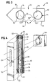
- the present invention relates to a unique illumination system 10 that is comprised of a light integrated chamber 12, made preferably of aluminum, having at least two lamps 14 for emitting light from the chamber 12, a power supply (not shown) for illuminating the lamps 14, and a reflective interior surface.
- the chamber 12 has a large cavity for containing the lamps 14 and a front panel 16, rear panel 18, a top panel 20, bottom panel 22 and side panels 23.
- Light is emitted from the chamber 12 through an elongated opening 24 in the front panel 16 of the chamber 12 (i.e. front opening 24).
- an elongated opening 26 is also located on the rear panel 18 of the chamber 12 (i.e. rear opening 26). This rear opening 26 corresponds in size and shape, and is positioned in alignment with, the front opening 24.
- this illumination system 10 is used in connection with a scanning system for scanning objects that pass in front of the illumination system 10.
- a scanning system for scanning objects that pass in front of the illumination system 10.
- a scanning mechanism such as a camera 28 or other like device.
- the information on the object is read by the scanning mechanism or camera 28 through the front and rear openings 24 and 26 of the illumination system 10. While it is illustrated that this illumination system 10 be used in connection with a scanning mechanism, such as a camera 28, the illumination system 10 of the present invention can used in connection with other applications that require illumination of objects.
- the unique aspect of the present invention is the encompassing and the placement of the two lamps 14 within the chamber 12.
- the lamps 14 of the present invention are high voltage, high frequency lamps that have a phosphorous coating 34 on the interior of the lamps 14, such as a florescent 9-watt bulb or similar type lamp.
- a small amount of the phosphorous coating 34 is scraped off the inside of each lamp 14 to form an approximately 1/10" in width slot 30 that runs the entire length of the longitudinal axis of each lamp 14.
- This slot 30 allows each lamp 14 to emit a small amount of direct light from the lamp 14 through the front opening 24 of the chamber 12.
- Each lamp 14 is then positioned with the chamber 12 so that the direct light emitted from the slot 30 in the lamp 14 is focused toward the front opening 24 of the chamber 12. While it is preferred that the slot 30 run the entire length of each lamp 14, it is only necessary that the slot 30 run at least the length of the front opening 24 when each lamp 14 is secured within the illumination chamber 12.
- the two lamps 14 are positioned such that one lamp 14 is on one side of the elongated openings 24 and 26 and the other lamp 14 is on the opposing side of the openings 24 and 26 and such that the longitudinal axis of each lamp 14 runs parallel to the longitudinal axis of the front and rear openings 24 and 26. Similarly, the lamps 14 are positioned far enough to each side of the openings 24 and 26 so that the lamps 14 do not obstruct the view of the scanning mechanism through the openings 24 and 26.
- Each lamp 14 is held within the chamber 12 and powered by two sockets 32.
- a total for four sockets 32 are contained within the chamber 12 for maintaining and powering the lamps 14.
- Two of the sockets 32 are on the interior of the top panel 20 of the chamber 12, while the other two sockets 32 are positioned on the interior of the bottom panel 22 of the chamber 12 in alignment with the two sockets 32 positioned on the top panel 20 of the chamber 12.
- Each lamp 14 will therefore be held at its top by one socket 32 and at its bottom by another.
- each lamp 14 the direct light emitted from the slot 30 in each lamp 14 is directed toward the front opening 24 of the chamber 12.
- the lamps 14 are positioned so that the elongated slot 30 of each lamp 14 is preferably at a forty-five degree (45°) angle relative to the front opening 24.
- the light emitted from each slot 30 will be at a ninety degree (90°) angle from the light omitted from the other.
- the maximum amount of direct light is emitted from the chamber 12 through the front opening 24.
- the focusing and use of such direct light through the front opening 24 creates an intense illuminating light.
- the angle of the direct light be positioned at a forty-five degree (45°) angle relative to the front opening, various angles can be utilized for the direction of direct light through the front opening 24. For example, any angle between the range of twenty degrees (20°) and sixty-five degrees (65°) can be used. A variation in this angle may even be preferred depending upon the application. A lesser degree angle from the front opening 24 will create a direct light projection that covers a broader area, while a larger angle will provide a greater depth of field.
- the intense illumination provided by the direct light works in conjunction with the diffused light being emitted through the phosphorous covered portions 34 of the lamps 14 to supply an intense, uniform array of light on the objects to be scanned.
- the integrated chamber 12 is preferably made of aluminum.
- the interior surfaces of the front panel 16 and side panels 23 of the chamber 12 are polished to create a reflective surface, while the interior surface of the rear panel 18 is covered with a highly reflective material such as white titanium paint or the like to create a rear surface having higher reflective properties than the interior surfaces of the front and side panels 16 and 23.
- a highly reflective material such as white titanium paint or the like to create a rear surface having higher reflective properties than the interior surfaces of the front and side panels 16 and 23.
- a rear surface with higher reflective properties more light is reflected toward the front of the chamber 12, thereby increasing the chances of diffused light escaping through the front opening 24 of the chamber 12 rather than the rear opening 26.
- aluminum is the preferred material for the chamber 12, other materials that have either reflective properties or are coated to have reflective properties may used with the present invention.
- the key aspect of the chamber 12 design is that the diffused light emitted through the phosphorous portion 34 of the lamp 14 is reflected off the interior surfaces of the chamber 12 until the reflected light escape
- a small light monitor 36 may be placed within the chamber 12 to monitor the intensity of the light source. Over time, the lamps 14 tend to accumulate dust or simply dim with age. The light monitor 36 will then detect any decrease in the light level and signal the lamp power supply to increase the output current to compensate for the decreased efficiency of the lamps 14. By increasing the current, the intensity of the lamps 14 will proportionately increase.
- the illumination system 10 of the present invention may be equipped with a small fan (not shown) placed at the bottom of the chamber 12 for forcing air into the chamber 12. Since the lamps 14 are preferably 9-watt florescent bulbs, there is no need to cool the lamps 14. The purpose of the fan therefore is to cause a small amount of static pressure to build up inside the chamber 12 and help to deflect dust from entering into the chamber 12.
- the present invention preferably functions to illuminate the surface of a material, such as an envelope or other material displaying useful and desirable information, and enable efficient reading and recording of the information on such material.
- a material such as an envelope or other material displaying useful and desirable information
- the address must be read from each piece of mail and captured by camera 28 to properly sort and route each piece of mail.
- each piece of mail rapidly passes before the illuminating system 10 such that the necessary information on the mail piece can be viewed through the front and rear openings 24 and 26 of the illumination system 10.
- the illumination system 10 then, through its intense, uniform, scattered light output, illuminates the area before the system 10 so that camera 28, or other scanning device, can read and record the information on the mail piece.
- the camera 28 views and records the information as the information on each mail piece passes in front of the openings 24 and 26.
Landscapes
- Engineering & Computer Science (AREA)
- Multimedia (AREA)
- Signal Processing (AREA)
- Non-Portable Lighting Devices Or Systems Thereof (AREA)
Applications Claiming Priority (2)
| Application Number | Priority Date | Filing Date | Title |
|---|---|---|---|
| US09/193,982 US6726343B2 (en) | 1998-11-18 | 1998-11-18 | Integrated chamber illumination system |
| US193982 | 1998-11-18 |
Publications (2)
| Publication Number | Publication Date |
|---|---|
| EP1003321A2 true EP1003321A2 (de) | 2000-05-24 |
| EP1003321A3 EP1003321A3 (de) | 2001-03-07 |
Family
ID=22715854
Family Applications (1)
| Application Number | Title | Priority Date | Filing Date |
|---|---|---|---|
| EP99309213A Withdrawn EP1003321A3 (de) | 1998-11-18 | 1999-11-18 | Integrierte Kammer mit Beleuchtungssystem |
Country Status (2)
| Country | Link |
|---|---|
| US (1) | US6726343B2 (de) |
| EP (1) | EP1003321A3 (de) |
Families Citing this family (6)
| Publication number | Priority date | Publication date | Assignee | Title |
|---|---|---|---|---|
| US7304312B2 (en) * | 2005-09-07 | 2007-12-04 | Access Business Group International Llc | Ultraviolet reflecting compositions |
| US8220957B2 (en) * | 2007-02-12 | 2012-07-17 | Abl Ip Holding Llc | Retrofit light assembly |
| US20090244908A1 (en) * | 2008-04-01 | 2009-10-01 | Stephen Haight Lydecker | Louver for Light Assembly |
| USD640825S1 (en) | 2008-04-24 | 2011-06-28 | Abl Ip Holding Llc | Louver |
| USD612534S1 (en) * | 2008-04-24 | 2010-03-23 | Abl Ip Holding Llc | Bracket |
| USD612978S1 (en) * | 2008-10-28 | 2010-03-30 | DTT Group LLC | Lamp base unit |
Family Cites Families (21)
| Publication number | Priority date | Publication date | Assignee | Title |
|---|---|---|---|---|
| US2201153A (en) * | 1939-06-13 | 1940-05-21 | William A Brown | Lighting and air impelling device |
| US3103156A (en) * | 1961-03-30 | 1963-09-10 | Emerson Electric Mfg Co | Area lighting and air exchange apparatus |
| US3407325A (en) * | 1965-09-28 | 1968-10-22 | Sylvania Electric Prod | Fluorescent manganese activated magnesium gallate phosphor and lamp |
| US3717781A (en) * | 1969-09-19 | 1973-02-20 | Sylvania Electric Prod | Aperture fluorescent lamp having uniform surface brightness |
| US4435732A (en) | 1973-06-04 | 1984-03-06 | Hyatt Gilbert P | Electro-optical illumination control system |
| US4730930A (en) | 1986-06-24 | 1988-03-15 | Technical Arts Corporation | Scanning apparatus and method |
| JPS6324759A (ja) * | 1986-07-16 | 1988-02-02 | Konica Corp | 読取装置 |
| US4868383A (en) * | 1988-09-08 | 1989-09-19 | Eastman Kodak Company | Linear integrating cavity light source used for generating an intense beam of light |
| US5207504A (en) * | 1991-07-03 | 1993-05-04 | Swift Gerald R | Method and apparatus for tuning strip flourescent light fixtures |
| US5399852A (en) | 1993-02-19 | 1995-03-21 | United Parcel Service Of America, Inc. | Method and apparatus for illumination and imaging of a surface employing cross polarization |
| US5555065A (en) | 1993-05-24 | 1996-09-10 | Nikon Corporation | Camera display illumination device which switchably illuminates displays |
| US5677939A (en) | 1994-02-23 | 1997-10-14 | Nikon Corporation | Illuminating apparatus |
| JPH07287317A (ja) * | 1994-04-15 | 1995-10-31 | Mita Ind Co Ltd | 画像形成装置 |
| US5570947A (en) * | 1994-11-08 | 1996-11-05 | Felland; Garold M. | Light fixture |
| US5645337A (en) | 1995-11-13 | 1997-07-08 | Interstate Electronics Corporation | Apertured fluorescent illumination device for backlighting an image plane |
| US5804818A (en) * | 1996-01-30 | 1998-09-08 | Eastman Kodak Company | Coated internally reflecting optical element |
| US5814802A (en) * | 1996-02-23 | 1998-09-29 | Accu-Sort Systems, Inc. | High speed imaging apparatus for CCD based scanners |
| US5701015A (en) | 1996-08-19 | 1997-12-23 | Eastman Kodak Company | Infrared illumination system for digital camera |
| US5803589A (en) * | 1997-01-10 | 1998-09-08 | Lee; Chi-Hsiang | Ceiling lighting fixture |
| US5717964A (en) | 1997-02-18 | 1998-02-10 | Eastman Kodak Company | Camera exposure apparatus having flash tubes for correcting for overexposure |
| US5921666A (en) * | 1997-03-04 | 1999-07-13 | Thomas Lighting | Ellipsoidal slot light |
-
1998
- 1998-11-18 US US09/193,982 patent/US6726343B2/en not_active Expired - Fee Related
-
1999
- 1999-11-18 EP EP99309213A patent/EP1003321A3/de not_active Withdrawn
Also Published As
| Publication number | Publication date |
|---|---|
| US20020015301A1 (en) | 2002-02-07 |
| US6726343B2 (en) | 2004-04-27 |
| EP1003321A3 (de) | 2001-03-07 |
Similar Documents
| Publication | Publication Date | Title |
|---|---|---|
| KR100275143B1 (ko) | 기판 상에 있는 표시부를 식별하기 위한 광학식 문자 인식용 조명 시스템 | |
| US5469294A (en) | Illumination system for OCR of indicia on a substrate | |
| US6856440B2 (en) | Coplanar camera scanning system | |
| US4868383A (en) | Linear integrating cavity light source used for generating an intense beam of light | |
| US8004604B2 (en) | Coplanar camera scanning system | |
| US5051872A (en) | Hemispherical non-glare illuminator | |
| US5274228A (en) | Linear light source/collector with integrating cylinder and light pipe means | |
| JP3472750B2 (ja) | 表面検査装置 | |
| US6667762B1 (en) | Miniature inspection system | |
| CN101049022B (zh) | 用于识别玻璃板表面缺陷和体缺陷的检查系统和方法 | |
| JPH0718803B2 (ja) | コンピュータ制御による多重角照射システム | |
| US6726343B2 (en) | Integrated chamber illumination system | |
| JP3321905B2 (ja) | 棒状照明体 | |
| US5825945A (en) | Document imaging with illumination from lambertian surfaces | |
| US6177954B1 (en) | Miniature inspection system | |
| US6003992A (en) | Back lighting illumination system | |
| EP1337833A1 (de) | Vorrichtung zur analyse der charakteristika gemahlener produkte | |
| JPH11242002A (ja) | 観測装置 | |
| JP3597751B2 (ja) | 光学的情報読取方法および読取装置 | |
| JP2979521B2 (ja) | 照明光伝達治具 | |
| HK1014926B (en) | Illumination system for ocr of indicia on a substrate | |
| JPH09282512A (ja) | 刻印読取り装置 | |
| JPH06148442A (ja) | ライン状ライトガイド |
Legal Events
| Date | Code | Title | Description |
|---|---|---|---|
| PUAI | Public reference made under article 153(3) epc to a published international application that has entered the european phase |
Free format text: ORIGINAL CODE: 0009012 |
|
| AK | Designated contracting states |
Kind code of ref document: A2 Designated state(s): DE FR GB IT |
|
| AX | Request for extension of the european patent |
Free format text: AL;LT;LV;MK;RO;SI |
|
| PUAL | Search report despatched |
Free format text: ORIGINAL CODE: 0009013 |
|
| AK | Designated contracting states |
Kind code of ref document: A3 Designated state(s): AT BE CH CY DE DK ES FI FR GB GR IE IT LI LU MC NL PT SE |
|
| AX | Request for extension of the european patent |
Free format text: AL;LT;LV;MK;RO;SI |
|
| 17P | Request for examination filed |
Effective date: 20010903 |
|
| AKX | Designation fees paid |
Free format text: DE FR GB IT |
|
| STAA | Information on the status of an ep patent application or granted ep patent |
Free format text: STATUS: THE APPLICATION IS DEEMED TO BE WITHDRAWN |
|
| 18D | Application deemed to be withdrawn |
Effective date: 20040602 |