EP1003403B1 - Corps moule - Google Patents
Corps moule Download PDFInfo
- Publication number
- EP1003403B1 EP1003403B1 EP98945241A EP98945241A EP1003403B1 EP 1003403 B1 EP1003403 B1 EP 1003403B1 EP 98945241 A EP98945241 A EP 98945241A EP 98945241 A EP98945241 A EP 98945241A EP 1003403 B1 EP1003403 B1 EP 1003403B1
- Authority
- EP
- European Patent Office
- Prior art keywords
- shaped article
- article according
- active element
- segments
- shaped
- Prior art date
- Legal status (The legal status is an assumption and is not a legal conclusion. Google has not performed a legal analysis and makes no representation as to the accuracy of the status listed.)
- Expired - Lifetime
Links
- 230000008859 change Effects 0.000 claims description 14
- 230000000694 effects Effects 0.000 claims description 3
- 239000011248 coating agent Substances 0.000 claims 1
- 238000000576 coating method Methods 0.000 claims 1
- 239000011796 hollow space material Substances 0.000 claims 1
- 238000000465 moulding Methods 0.000 description 7
- 238000004806 packaging method and process Methods 0.000 description 7
- 239000004744 fabric Substances 0.000 description 6
- 238000004804 winding Methods 0.000 description 6
- 230000037237 body shape Effects 0.000 description 5
- 239000004033 plastic Substances 0.000 description 5
- TZCXTZWJZNENPQ-UHFFFAOYSA-L barium sulfate Chemical compound [Ba+2].[O-]S([O-])(=O)=O TZCXTZWJZNENPQ-UHFFFAOYSA-L 0.000 description 4
- 239000002184 metal Substances 0.000 description 4
- 238000006073 displacement reaction Methods 0.000 description 3
- 230000006978 adaptation Effects 0.000 description 2
- 238000005452 bending Methods 0.000 description 2
- 230000006835 compression Effects 0.000 description 2
- 238000007906 compression Methods 0.000 description 2
- 238000005516 engineering process Methods 0.000 description 2
- 239000000463 material Substances 0.000 description 2
- 230000003287 optical effect Effects 0.000 description 2
- 230000000399 orthopedic effect Effects 0.000 description 2
- 210000001015 abdomen Anatomy 0.000 description 1
- 230000009471 action Effects 0.000 description 1
- 239000013543 active substance Substances 0.000 description 1
- 239000000853 adhesive Substances 0.000 description 1
- 238000004026 adhesive bonding Methods 0.000 description 1
- 230000001070 adhesive effect Effects 0.000 description 1
- 230000000712 assembly Effects 0.000 description 1
- 238000000429 assembly Methods 0.000 description 1
- 230000005540 biological transmission Effects 0.000 description 1
- 238000010276 construction Methods 0.000 description 1
- 238000013016 damping Methods 0.000 description 1
- 230000003247 decreasing effect Effects 0.000 description 1
- 239000000835 fiber Substances 0.000 description 1
- 238000004519 manufacturing process Methods 0.000 description 1
- 230000007246 mechanism Effects 0.000 description 1
- 230000002265 prevention Effects 0.000 description 1
- 238000005096 rolling process Methods 0.000 description 1
- 239000007787 solid Substances 0.000 description 1
- 230000000087 stabilizing effect Effects 0.000 description 1
- 230000003319 supportive effect Effects 0.000 description 1
- 230000009466 transformation Effects 0.000 description 1
- 238000003466 welding Methods 0.000 description 1
- 239000002023 wood Substances 0.000 description 1
Images








Classifications
-
- A—HUMAN NECESSITIES
- A47—FURNITURE; DOMESTIC ARTICLES OR APPLIANCES; COFFEE MILLS; SPICE MILLS; SUCTION CLEANERS IN GENERAL
- A47C—CHAIRS; SOFAS; BEDS
- A47C7/00—Parts, details, or accessories of chairs or stools
- A47C7/36—Supports for the head or the back
- A47C7/40—Supports for the head or the back for the back
- A47C7/46—Supports for the head or the back for the back with special, e.g. adjustable, lumbar region support profile; "Ackerblom" profile chairs
-
- A—HUMAN NECESSITIES
- A47—FURNITURE; DOMESTIC ARTICLES OR APPLIANCES; COFFEE MILLS; SPICE MILLS; SUCTION CLEANERS IN GENERAL
- A47C—CHAIRS; SOFAS; BEDS
- A47C31/00—Details or accessories for chairs, beds, or the like, not provided for in other groups of this subclass, e.g. upholstery fasteners, mattress protectors, stretching devices for mattress nets
- A47C31/12—Means, e.g. measuring means, for adapting chairs, beds or mattresses to the shape or weight of persons
- A47C31/123—Means, e.g. measuring means, for adapting chairs, beds or mattresses to the shape or weight of persons for beds or mattresses
-
- A—HUMAN NECESSITIES
- A47—FURNITURE; DOMESTIC ARTICLES OR APPLIANCES; COFFEE MILLS; SPICE MILLS; SUCTION CLEANERS IN GENERAL
- A47C—CHAIRS; SOFAS; BEDS
- A47C31/00—Details or accessories for chairs, beds, or the like, not provided for in other groups of this subclass, e.g. upholstery fasteners, mattress protectors, stretching devices for mattress nets
- A47C31/12—Means, e.g. measuring means, for adapting chairs, beds or mattresses to the shape or weight of persons
- A47C31/126—Means, e.g. measuring means, for adapting chairs, beds or mattresses to the shape or weight of persons for chairs
-
- A—HUMAN NECESSITIES
- A47—FURNITURE; DOMESTIC ARTICLES OR APPLIANCES; COFFEE MILLS; SPICE MILLS; SUCTION CLEANERS IN GENERAL
- A47C—CHAIRS; SOFAS; BEDS
- A47C7/00—Parts, details, or accessories of chairs or stools
- A47C7/36—Supports for the head or the back
- A47C7/40—Supports for the head or the back for the back
- A47C7/46—Supports for the head or the back for the back with special, e.g. adjustable, lumbar region support profile; "Ackerblom" profile chairs
- A47C7/462—Supports for the head or the back for the back with special, e.g. adjustable, lumbar region support profile; "Ackerblom" profile chairs adjustable by mechanical means
Definitions
- the invention relates to moldings that can be used in many fields of technology, for. B. they can be used on backrests of seating furniture, e.g. B. the backrest curvature to be able to adapt individually to the people sitting on the seating furniture.
- an adjustable back support with a shield is known by means of an upper and a lower clamping element, which are individually adjustable, is adjustable.
- the moldings are also under construction for supporting various molded components, in assemblies as supports for securing in the area of packaging for Prevention of damage to goods in medical technology such. B. in couches, use orthopedic shoes, etc. and wherever certain types of space should be changeable for optical, technical, medical reasons, e.g. Belly adjustable supports.
- the object of the invention is three-dimensional molded articles with integrated curvature to indicate that in a simple and easy manner deviates from the original form can take different spatial forms and / or are adaptable, e.g. to also to be able to offer sufficient support functions.
- the invention allows a molded body, the unloaded three-dimensional Eigenform at least one integrated bulge, e.g. any triangular Cross-sectional shape has by applying force in one molded body with another Transform your own shape in whole or in part, whereby the effort and thus the spatial transformation can take place continuously or step by step.
- the maximal Deformation is achieved with the maximum permissible force, when the Applying force reduces the deformation until the load is completely relieved original shape is reached again.
- a wire, a tape, a strand, a belt, or a web can be used as the active element braided synthetic or natural fibers or metal threads, a round or profile rod Plastic or metal, a sheet metal strip or the like can be used, only one sufficient flexible flexibility and sufficient for the forces to be applied Resistance is given at least in the direction of attack and transmission of a force have to be. It is also possible e.g. B. a tension or compression element in the tension or compression direction with different elasticities, e.g. B. using spring elements, for example for damping and / or to subdivide it, with a between the parts any suitable device for applying forces to the active elements can be included.
- the shape-changeable molded body can, for. B. a one-part or multi-part spatial body be suitable to absorb supporting forces on the one hand and to apply them to the active elements transferred or vice versa. It can be made of a plastic, especially a foamed one Plastic, be designed as a cushion body and also non-deformable parts contain.
- the molded body can in turn consist of individual elements that form molded bodies exist, which in turn individually or too several can be arranged together movable or fixed against each other. in which also the arrangement on a holder or carrier or with a flexible cover or is possible in a flexible envelope, the latter also being elastic.
- the deformable parts of the molded body can also on or on a fixed part. e.g. B. a core of wood.
- Metal or plastic can be arranged or from a plurality fixed parts movable against each other.
- a holder or carrier z. B. serve backrests, seats. Beach chairs, optical and other advertising material. Backdrops, Camouflage devices. Tools, tool fixtures. Support structures and All kinds of frames, a mattress part, a bed frame, a packaging container or a Containers, shoes and much more.
- a molded body can also consist of individual solid Segments exist that are loosely next to each other or articulated with an active element, a carrier, holder or the like are connected. The latter can also be integrally z. B. from be made of a plastic.
- Any device can be used to change the forces to be applied, which is able to apply a force by means of the active elements to the molded body or bodies to exercise, the active elements being both relaxed and tense can.
- An arrangement is also possible which allows one or the other Shaped body to exert pressure.
- the device can be mechanical or motorized be powered and directly or remotely controlled, e.g. B. by means of a Bowden cable or a linkage or pneumatically, hydraulically, electrically or by radio.
- connection between the shaped bodies and the active element (s) can be any way, e.g. B. done by gluing, welding, riveting, etc. in individual cases only by friction, if z. B. the molded body in a closed shell is arranged.
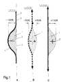
- Fig. I a basic principle of the invention based on a shape-changeable Shaped body 1 shown in three different shapes.
- the molded body 1 is in Fig. 1A in the rest position, d. H. represented in its intrinsic form, which in the exemplary embodiment consists of a flat base area 2 and a curvature 3 consists. which is symmetrical in cross section in the exemplary embodiment as rounded isosceles triangle is designed but can also be asymmetrical.
- a connecting means 4 which, for. B. an elastic adhesive can be. any active element 5, z. B. in the form of a flexible drawstring 6 attached.
- the shape-changeable and elastic molded body is longitudinal (in 1A from top to bottom) designed slightly stretchy, whereas it in the transverse direction is almost pressure-resistant. If a tensile force is applied to the tension band 6 at one end, then the other end lying behind the molded body 1 is fixed in position, or a tensile force is applied at both ends (see the arrows in FIG. 1B) begins to stretch the drawstring 6 and press the molded body 1 elastically deforming it before it reaches the end position shown in FIG. 1C. in which the molded body 1 a has a mirror-symmetrical shape to the starting position, d. H. the curvature is 3 ' then facing the opposite side to the starting position.
- FIG. 2 shows a seat back with a support structure 7 z. B. in the form of a bowl. which is a trough-like Bulge 8 has.
- An active element 5 is in shape above the bulge 8 attached a tension belt 9, which is designed so that it relaxes in the bulge 8th can concern.
- the device 10 can, for. B. a winder for a drawstring 6 or a tension belt 9 or a rope or a strip of cloth.
- the back support has a curvature 3 which corresponds to the shape of the bulge 8 or vice versa.
- the parts of the back support without bulge, which are in the upper and lower part are located outside the bulge 8 of the shell be detachable or fixed.
- a detachable connection is e.g. B. by Velcro or push buttons realizable.
- a conceivable attachment of the tension belt 9 in the area the bulge 3 is not necessary here, since the molded body 1 There is frictional contact.
- a simple embodiment consists of a shaped body such as it is described in Fig. 1, the curvature with a serving as an active element z. B. is connected from a fabric.
- the upper free end of the fabric is fixed z. B. on a cross strut and below the molded body is a winder fixed in position with which the winding and unwinding of the fabric and thus its tightening and thus the shape of the molded body is also possible.
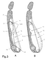
- the backrest shown in Fig. 3 with headrest consists of a support structure 7 'in Form of a foamed rigid back part on the one in the upper area Headrest is arranged and which has a cavity 11 which u. a. to record the shape-changeable molded body 1 is used.
- the device 10 for Applying forces self-locking and with a Bowden cable arrangement 12 connected part of the cable 13 with the curvature 3 of the molded body 1 connected is.
- the cable 13 is guided around two deflection points 14, 14 '.
- the Bowden cable arrangement 12 can be used with any device 10 for application of forces, here to shorten and lengthen the cable 13 by which the Desired change in shape of the molded body 1, as described above, causes will be provided.
- the side on which a user leans is the most stable Back part a flexible covering the cavity 11 and the molded body 1 Cover 15 arranged, which can also serve as padding and for cushioning and lies loosely on the molded body 1 or can also be connected to it.
- Another embodiment variant is that either on the top or on the lower end or at both ends the drawstrings or straps on the holder redirected and led to the back.
- the device 10 Through the two deflection points 14. 14 ', it is possible for the device 10 to apply the active forces in the rear Area d. H. can also be arranged hidden.
- the redirection increased friction through appropriate measures. such as B. arranged on axes Rollers are reduced.
- Fig. 3 above and below redirected, there is also the possibility of observing the respectively set changed shape of the molded body 1, to move this up and down. This can e.g. B. in that one of the deflection points 14 or 14 'for the cable 13 as Pivot bearing (not shown) is designed.
- the arrangement of the Device 10 for applying the forces must not hinder this movement.
- the Device 10 for applying forces can itself move up and down be arranged. so that by moving up and down the desired one Height adjustment is feasible.
- the in Fig. 4A The illustrated embodiment represents an independent module that, for. B. as a whole locked in a seat frame without tools z. B. can be hung.
- the in Fig. 4B is designed as a mobile transportable backrest.
- the Shaped body 1 of the backrests correspond to the above in shape and function Shaped bodies described, so that only deviations is pointed out.
- there is also an active element 5 in the form of a Traction element 6 is provided, which at the upper end of a hook-shaped here upper end 16 (Fig. 4A) is attached.
- the hook-shaped end 16 is z. B. attachable to a crossbar 17, the z. B. to a seat frame (support structure 7) heard.
- the lower end of the tension element 6 is with the device 10 for Applying forces in conjunction with a winder Eccentric can be designed.
- the hook-shaped end 16 can be connected to a rear wall 7 'or be designed in one piece with it.
- Seat frames are arranged hooks 18, clips, eyelets or the like, with the help of which the Module on the seat frame. preferably without tools. can be attached.
- the module can have any support structure without a rear wall.
- the frame 19 can also be designed as a shell, in which a bulge 8 is integrated.
- the active element is 5.
- the active element 5 can also consist of several tension belts arranged side by side. being their Attachment z. B.
- B winding or Tensioning devices also at the upper end of the backrest: can be and that the actuation is also spaced, e.g. B. can be done by a Bowden cable arrangement.
- a motorized drive that is electrically, hydraulically or pneumatically driven can be used.
- the winding or tensioning device can be made using Screws, threads, eccentrics etc. also have self-locking properties, the one with an adjustment by means of a handwheel or a lever Locking in any desired position automatically guaranteed, without having to actuating locks or releasable locking devices must be used.
- Fig. 5 shows a shoe with orthopedic support by means of a shape-changeable Shaped body 1.
- the molded body 1 is covered by a flexible sole 27.
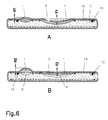
- a mattress is shown, the two in the longitudinal direction changeable Shaped body 1 and 1 ', one in the head area and one in the pelvic area.
- frame elements are provided on which the active elements 5 and / or Devices 10 for applying forces are attachable. where appropriate Deflections and supports can be provided.
- the mattress also points a body z.
- B. a foamed body in which the bulges 8.8 ' and / or free spaces are provided for the molded bodies 1 and 1 ', and one closed cover 15.
- Fig. 7 shows an application of the invention within a bed frame, wherein in In the longitudinal direction, three shape-changeable molded bodies 1, 1 ', 1 "are provided and one similar effect to a slatted frame.
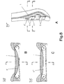
- Fig. 8 shows a vertical section through a seat back (Fig. 8A), in which a Vertical and transverse direction of moldable body 1 is shown. that too transverse active elements 5 in the form of drawstrings 6 ', 6 "are assigned to to achieve a change in shape also over the cross section (see Fig. 8B and C). in which in the transverse direction also only one active element or other such active elements can be provided.
- Fig. 9 shows a cross section through a packaging container 28 with two Boomerang-like changeable moldings 1, 1 ', the wings of each Adjacent walls of the packaging container 28 (own shape).
- To the other Surfaces of the shaped bodies 1, 1 ′ that abut the walls are effective elements 5 Drawstrings 6, 6 'arranged at one end near one of the corners 29. 29' (Fig. 9A) of the packaging container 28, in which the two molded bodies 1 and 1 ' encounter, fastened and at the other end in a self-locking tensioning or Winding device are introduced as a device 10 for applying forces.
- shaped bodies 1, 1 'can have incisions 30 and / or wedge-shaped Columns are provided, which allow better adaptation of the changeable molded bodies 1, 1 ' to the respective forms of goods to be transported 31 or a Make shape change easier.
- the transportation lock is by means of Shapeable body 1, 1 'shown on three different goods 31. It goes without saying that for certain purposes the use of only one or a larger number of moldings 1 for any shape Packaging container 28 is possible. Even the initial form of the changeable Shaped body 1, 1 'can be adapted to any packaging goods 31 in advance.
- Fig. 10 the action of forces at two spaced locations 32 and 33 is Active element 5 shown, which is connected to a molded body 1, whereby in Embodiment a vertex displacement of a curvature 3 from S1 to S2 and back, depending on the given initial form, is possible, with the two spaced points 32 and 33 in any combination tensile forces, if necessary also pressure forces, applied to the active element 5 with different intensities or can be dismantled.
- This is a wide variation in the change of Shaped body 1 given by changing the position and / or the number of Attack points 32, 33 can be varied further. It is also possible to add more
- active elements 5 that transmit forces in any other directions enable so that the molded body 1 are subjected to further deformations can, with other main and side effects such.
- B. vibration and / or Massage movements can be achieved.
- Fig. 11 is a molded body 34 in the form of a resilient in the longitudinal direction Body shown. who stiffen in the transverse direction. in approximately parallel folds increasing and then decreasing pleat height is designed, d. H. he points in his Starting form a linear base 2 and a curvature 3.
- the illustrated embodiment is the active element assigned to the molded body 34 5, a drawstring 6, around two deflection points 14, 14 ', the two ends 6a and 6b of the drawstring 6 (see FIGS. 11C and D) over a distance between the ends 6a and 6b adjustable device 35 are interconnected.
- one of the deflection points 14 or 14 ' is adjustable in relation to the other arranged. Are the two deflection points 14, 14 ', as shown in Fig.
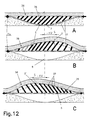
- FIG. 12 shows a further variant of a device for changing a Shaped body and additional displacement of the vertex of the relocated Curvature 3 'of a shaped body 36 is shown.
- the molded body 36 consists of Segments 37 that are spaced apart on any flexible support 38 are hinged, their other ends also hinged to a flexible Active element 5 are attached.
- the segments 37 are at an angle to Arranged horizontally.
- the heights of the individual segments 37 selected for horizontal so that their vertices one Bow, d. H. describe a curvature 3.
- Fig. 13 has a similar structure. how he is described in Fig. 12. however, a molded body 39 is provided here in which symmetrical to the center line, the individual segments 37 'of the right versus those the left side symmetrical but with opposite angles to the horizontal arranged and articulated with the active element 5 and the support 38 are connected. A uniform bulge is achieved in that from both ends on the Active element 5 is applied a uniform train. Will the train of both Applied ends unevenly, a shift of the Show vertices within certain limits.
- the molded body 39 ' has the shape shown in FIG. 13 described configuration.
- the active element 5 is on both Fixed ends and in the middle between the two segments 37 ' opposite angular arrangement separately and with a device 35 'for Provide distance adjustment of the separated ends. When the ends touch, i. H. the distance becomes zero, the bulged position of the Shaped body 39 reached.
- a molded body 40 which consists of individual There are segments 37 "that are freely movable against each other, but against each other supportive form a molded body 40 with a downward curvature 3.
- an active element 5 in a corresponding to the curvature 3 Bulge 8 arranged and over the molded body 40 is a flexible cover 15.
- the cover 15 and the active element 5th forms an enclosed molded body 40, there is no connection with either Active element 5 still required with the cover 15, since the individual segments 37 " lie against each other and support each other and from below by the active element 5 being held.
- the tensile force is preferably applied applied at both ends.
- 15B is a view of the active element 5 being stretched modified arch element 40 shown, its new curvature 3 'in the starting position points in the opposite direction.
- 16 shows an embodiment of a molded body 41 in which the Individual segments 37 '' 'are arranged in a herringbone manner and the active element 5 in each case hingedly connected to them between the upper and lower segments 37 ′′, optionally also with 'longitudinal slip'.
- Is on the active element 5, which is fixed at one end to the last pair of segments is connected in an articulated manner with slip, a force is applied, the molded body 41, the in the rest position s. 16A and C is extremely flat in a balloon shape Body s. 16B and D transform.
- the active element 5 does not form a straight line, but rather a straight line Curve.
- 17 and 18 are embodiments of a shape-changeable molded body 43 shown, the z. B. on one level or arbitrarily designed vaulted surfaces work, d. H. without a real bulge into which the Shaped body is inserted or originally arranged.
- 17 is a plate 44 shown, on which the shaped body 43 is arranged, which is at a distance from one another on the plate 44 articulated segments 37 of different heights, whose free ends are articulated to an active element 5, and on the if necessary, a cover 15 can be arranged.
- the molded body 43 In the one shown in Fig. 17A In the rest position, the molded body 43 assumes its flattest shape, i. H. his Starting position.
- the segments 37 With a tensile force applied to the active element 5 in the direction of 17B, the segments 37 line up and the molded body 43 becomes arched If the segments 37 are perpendicular with respect to the plate 44, the Curvature the maximum vertex height. If the Vertex height must have a return force, e.g. B. in the form of a spring or thrust force, be provided for pivoting the segments 37.
- a return force e.g. B. in the form of a spring or thrust force
- FIG. 18 The embodiment of a shaped body 45 shown in FIG. 18 is similar to that in FIG Fig. 17 constructed.
- the segments 37 are articulated on one preferably bending-resistant active agent 50 as active element 5 at a distance from one another attached instead of directly on the plate 44 as in the embodiment of FIG. 17.
- the plate 44 serves as a support and / or guide for the active element 5 z.
- Legs Drawbar 46 The free ends of the segments 37 are here on a cover 15 articulated attached.
- a tensile force is applied in the direction of the arrow in Fig. 20B is, the segments 37 are erected and it is formed according to their Length dimensions and their arrangement a curved shaped body.
- a dimensionally stable active element 5 can during a further movement of the Active element 5 again weakened the curvature achieved in one position be where the segments 37 abut each other only in opposite directions Direction to the position shown in Fig. 18A. If the cover 15 a Has inherent elasticity, d. H. can exert a force on the segments 37 can Active element 5 also consist of any flexible tensile material. there then the return of the segments 37 to the starting position by the elasticity and resilience of the cover 15 can be effected, if a possible Self-locking is excluded by suitable measures.
Landscapes
- Mechanical Engineering (AREA)
- Engineering & Computer Science (AREA)
- Orthopedics, Nursing, And Contraception (AREA)
- Mattresses And Other Support Structures For Chairs And Beds (AREA)
- Glass Compositions (AREA)
- Lining Or Joining Of Plastics Or The Like (AREA)
- Prostheses (AREA)
- Finger-Pressure Massage (AREA)
- Organic Insulating Materials (AREA)
- Inorganic Insulating Materials (AREA)
- Blow-Moulding Or Thermoforming Of Plastics Or The Like (AREA)
- Footwear And Its Accessory, Manufacturing Method And Apparatuses (AREA)
- Polymers With Sulfur, Phosphorus Or Metals In The Main Chain (AREA)
- Bedding Items (AREA)
- Buffer Packaging (AREA)
- Polyurethanes Or Polyureas (AREA)
- Chair Legs, Seat Parts, And Backrests (AREA)
- Materials For Medical Uses (AREA)
- Diaphragms For Electromechanical Transducers (AREA)
- Medicinal Preparation (AREA)
- Physical Or Chemical Processes And Apparatus (AREA)
- Toys (AREA)
- Moulds For Moulding Plastics Or The Like (AREA)
- Casting Or Compression Moulding Of Plastics Or The Like (AREA)
Claims (32)
- Corps de forme contenant au moins un corps de forme (1), dont la forme volumique tridimensionnelle non chargée peut être déplacée avec une partie unilatérale intégrée et à l'aide d'un élément d'action flexible (5) relié au corps de forme (1) le long de la partie cintrée, moyennant l'application d'une force de compression et/ou de traction variable à l'élément d'actionnement flexible (5) et/ou peut être transformée en totalité ou en partie au moyen déplacement sur elle-même, en une autre forme de volume tridimensionnelle.
- Corps de forme selon la revendication 1, caractérisé en ce qu'une des autres formes volumiques tridimensionnelles du corps de forme (1), dans laquelle ce corps peut être amené par conversion, et sa forme volumique symétrique de la forme volumique non chargée.
- Corps de forme selon la revendication 1 ou 2, caractérisé en ce que l'élément d'actionnement (5) est agencé de manière à être flexible et de manière à pouvoir être presque non dilatable linéairement.
- Corps de forme selon l'une des revendications 1 à 3, caractérisé en ce que l'élément d'actionnement (5) est un élément de traction (6).
- Corps de forme selon l'une des revendications 1 à 4, caractérisé en ce que chaque élément d'actionnement (5) est disposé sur au moins une structure d'appui (7) avec possibilité de modification de l'action de force.
- Corps de forme selon l'une des revendications 1 à 5, caractérisé en ce que la structure d'appui (7) est un cadre.
- Corps de forme selon l'une des revendications 1 à 6, caractérisé en ce que plusieurs éléments d'actionnement (5) attaquent le corps de forme (1) dans différentes directions.
- Corps de forme selon l'une des revendications 1 à 7, caractérisé en ce que plusieurs éléments d'action (7) attaquent des emplacements différents sur le corps de forme (1).
- Corps de forme selon l'une des revendications 1 à 8, caractérisé en ce qu'au moins un élément d'actionnement (5) situé sur la structure d'appui (7) subit un changement de direction.
- Corps de forme selon la revendication 9, caractérisé en ce que le changement de direction s'effectue à l'aide d'un rouleau de renvoi rotatif.
- Corps de forme selon l'une des revendications 1 à 10, caractérisé en ce qu'à ce corps est associé une partie en creux (8) ou une cavité (11), dans laquelle le corps de forme (1) peut pénétrer en totalité ou en partie lors d'une modification de la force appliquée à un ou plusieurs éléments d'actionnement (5), où dans laquelle il est disposé.
- Corps de forme selon l'une des revendications 1 à 11, caractérisé en ce que la force devant être appliquée d'au moins un élément d'actionnement (5) est réglable progressivement.
- Corps de forme selon l'une des revendications 1 à 12, caractérisé en ce que la force d'au moins un élément d'actionnement (5) est réglable pas à pas.
- Corps de forme selon l'une des revendications 1 à 13, caractérisé en ce les forces devant être appliquées de plusieurs éléments d'action (5) sont réglables en commun.
- Corps de forme selon l'une des revendications 1 à 14, caractérisé en ce que la force devant être appliquée d'au moins un élément d'actionnement (5) est réglable de manière autobloquante.
- Corps de forme selon l'une des revendications 1 à 15, caractérisé en ce qu'au moins un corps de forme (1) contient des parties déformables.
- Corps de forme selon l'une des revendications 1 à 16, caractérisé en ce qu'au moins un élément d'actionnement (5) comporte au moins une partie élastique.
- Corps de forme selon l'une des revendications 1 à 17, caractérisé en ce qu'au moins deux corps de forme (1, 1') sont reliés entre eux au moyen d'éléments de liaison.
- Corps de forme selon l'une des revendications 1 à 18, caractérisé en ce que plusieurs corps de forme (1, 1') peuvent être transformés en commun au moins dans une direction.
- Corps de forme selon l'une des revendications 1 à 19, caractérisé en ce qu'un ou plusieurs corps de forme peuvent être transformés, d'une manière décalée dans le temps, par des éléments d'actionnement (5).
- Corps de forme selon l'une des revendications 1 à 20, caractérisé en ce qu'un ou plusieurs corps de forme peuvent être transformés, avec un décalage local, par des éléments d'actionnement (5).
- Corps de forme selon l'une des revendications 1 à 21, caractérisé en ce que la force, qui doit être appliquée à un élément d'actionnement (5), est appliquée par voie mécanique et/ou électrique et/ou pneumatique et/ou hydraulique, directement ou indirectement.
- Corps de forme selon l'une des revendications 1 à 22, caractérisé en ce que le corps de forme (1) est légèrement extensible dans la direction longitudinale et résiste à la compression dans la direction transversale.
- Corps de forme selon la revendication 23, caractérisé en ce que l'extensibilité est obtenue au moyen d'entailles (3) formées dans le corps de forme.
- Corps de forme selon l'une des revendications 1 à 22, caractérisé en ce que le corps de forme est constitué de plusieurs segments (37).
- Corps de forme selon la revendication 25, caractérisé en ce que les segments (37) sont agencés de manière à être rigides au moins dans une direction.
- Corps de forme selon la revendication 25 ou 26, caractérisé en ce que les segments (37) sont reliés entre eux.
- Corps de forme selon l'une des revendications 25 ou 27, caractérisé en ce que les segments (37) sont reliés de manière à être déplaçables, par l'intermédiaire d'au moins un élément supplémentaire.
- Corps de forme selon la revendication 28, caractérisé en ce que l'élément supplémentaire est un élément d'actionnement (5), un appui (38), une enveloppe (42) ou une plaque (44).
- Corps de forme selon l'une des revendications 25 à 29, caractérisé en ce que les segments (37) ont des dimensions différentes, notamment des dimensions en hauteur différentes et sont disposés de manière à être déplaçables angulairement.
- Corps de forme selon l'une des revendications 25 à 30, caractérisé en ce que les segments (37) constitués par au moins deux parties et sont reliés entre eux de façon articulée.
- Corps de forme selon l'une des revendications 28 à 31, caractérisé en ce que l'élément supplémentaire et les segments sont réalisés d'un seul tenant.
Applications Claiming Priority (3)
| Application Number | Priority Date | Filing Date | Title |
|---|---|---|---|
| EP97114117 | 1997-08-14 | ||
| EP97114117A EP0897682B1 (fr) | 1997-08-14 | 1997-08-14 | Corps formé |
| PCT/EP1998/005157 WO1999008570A2 (fr) | 1997-08-14 | 1998-08-13 | Corps moule |
Publications (2)
| Publication Number | Publication Date |
|---|---|
| EP1003403A2 EP1003403A2 (fr) | 2000-05-31 |
| EP1003403B1 true EP1003403B1 (fr) | 2001-05-23 |
Family
ID=8227225
Family Applications (2)
| Application Number | Title | Priority Date | Filing Date |
|---|---|---|---|
| EP97114117A Expired - Lifetime EP0897682B1 (fr) | 1997-08-14 | 1997-08-14 | Corps formé |
| EP98945241A Expired - Lifetime EP1003403B1 (fr) | 1997-08-14 | 1998-08-13 | Corps moule |
Family Applications Before (1)
| Application Number | Title | Priority Date | Filing Date |
|---|---|---|---|
| EP97114117A Expired - Lifetime EP0897682B1 (fr) | 1997-08-14 | 1997-08-14 | Corps formé |
Country Status (13)
| Country | Link |
|---|---|
| US (2) | US6460208B1 (fr) |
| EP (2) | EP0897682B1 (fr) |
| JP (1) | JP2001514911A (fr) |
| KR (1) | KR20010022890A (fr) |
| CN (1) | CN1267199A (fr) |
| AT (2) | ATE187043T1 (fr) |
| AU (1) | AU735220B2 (fr) |
| BR (1) | BR9812123A (fr) |
| CA (1) | CA2307916A1 (fr) |
| DE (2) | DE59700802D1 (fr) |
| DK (1) | DK0897682T3 (fr) |
| ES (2) | ES2143275T3 (fr) |
| WO (1) | WO1999008570A2 (fr) |
Families Citing this family (14)
| Publication number | Priority date | Publication date | Assignee | Title |
|---|---|---|---|---|
| DE19916411A1 (de) | 1999-04-01 | 2000-11-16 | Leif Kniese | Dynamischer Hebel zur Verbesserung der Kraftübertragung |
| RU2144302C1 (ru) * | 1999-06-03 | 2000-01-20 | Канторов Дмитрий Аскольдович | Эргономическое ложе |
| US7137664B2 (en) | 2003-01-22 | 2006-11-21 | L&P Property Management Company | Automatically actuating ergonomic support system for a fold down seat |
| US6948199B2 (en) * | 2003-08-07 | 2005-09-27 | Global Advanced Systems, Llc | Bed foundation |
| WO2006029204A1 (fr) * | 2004-09-07 | 2006-03-16 | L & P Property Management Company | Mecanisme pour support lombaire de siege fin |
| US7300106B2 (en) * | 2006-03-30 | 2007-11-27 | Schukra Of North America, Ltd. | Trim foam lumbar |
| US7490899B2 (en) | 2006-03-30 | 2009-02-17 | Schukra Of North America | Combination lumbar-bolster system |
| US8156995B2 (en) | 2009-04-20 | 2012-04-17 | Rite-Hite Holding Corporation | Door element |
| US9162832B2 (en) | 2013-07-02 | 2015-10-20 | Rite-Hite Holding Corporation | Vehicle-actuated weather barrier apparatus |
| US10966527B2 (en) | 2017-06-09 | 2021-04-06 | Steelcase Inc. | Seating arrangement and method of construction |
| JP2018078272A (ja) * | 2016-10-31 | 2018-05-17 | スリーエム イノベイティブ プロパティズ カンパニー | 三次元形状熱伝導性成形体、及びその製造方法 |
| DE102018109486A1 (de) * | 2018-04-20 | 2019-10-24 | Klöber GmbH | Lordosenstütze für Sitzmöbel, vorzugsweise für Arbeitsstühle |
| DE102018119502A1 (de) * | 2018-08-10 | 2020-02-13 | Airbus Operations Gmbh | Passagiersitz mit einer erweiterbaren Rückenlehne |
| FR3117322B1 (fr) * | 2020-12-16 | 2026-01-02 | Sofkaparis Com | Elément de mobilier, notamment meuble, du type fauteuil, banquette, lit, sommier ou analogue |
Family Cites Families (11)
| Publication number | Priority date | Publication date | Assignee | Title |
|---|---|---|---|---|
| DE2064419C3 (de) | 1970-12-30 | 1979-08-30 | Recaro Gmbh & Co, 7000 Stuttgart | Rückenlehne für Kraftfahrzeugsitze |
| US3806968A (en) * | 1972-03-13 | 1974-04-30 | Bekins Moving & Storage Co | Orthopaedic back support appliance |
| US3973797A (en) * | 1975-03-31 | 1976-08-10 | Deere & Company | Seat backrest having an adjustable lumbar support |
| DE3324655C2 (de) * | 1983-07-08 | 1985-05-15 | Fa. Willibald Grammer, 8450 Amberg | Sitz mit Bandscheibenstütze |
| DE3620084A1 (de) * | 1986-06-14 | 1987-12-17 | Keiper Recaro Gmbh Co | Rueckenlehne fuer fahrzeugsitze |
| US4730871A (en) * | 1986-08-14 | 1988-03-15 | Nepsco, Inc. | Adjustable back rest |
| IT1211406B (it) * | 1987-10-16 | 1989-10-18 | Fiat Auto Spa | Schienale regolabile per sedili diveicoli particolarmente autovetture |
| ATE90187T1 (de) * | 1989-09-28 | 1993-06-15 | Stoll Kg Christof | Rueckenlehne mit einer hoehenverstellbaren lendenlordosen-unterstuetzung. |
| AU668427B2 (en) * | 1992-10-12 | 1996-05-02 | Henderson's Industries Pty Ltd | Adjustable lumbar support |
| US5367970A (en) * | 1993-09-27 | 1994-11-29 | The United States Of America As Represented By The Secretary Of The Navy | Controllable camber fin |
| US5651584A (en) * | 1995-04-24 | 1997-07-29 | L & P Property Management Company | Lumbar support structure for automotive vehicle |
-
1997
- 1997-08-14 EP EP97114117A patent/EP0897682B1/fr not_active Expired - Lifetime
- 1997-08-14 AT AT97114117T patent/ATE187043T1/de not_active IP Right Cessation
- 1997-08-14 DK DK97114117T patent/DK0897682T3/da active
- 1997-08-14 DE DE59700802T patent/DE59700802D1/de not_active Expired - Fee Related
- 1997-08-14 ES ES97114117T patent/ES2143275T3/es not_active Expired - Lifetime
-
1998
- 1998-08-13 WO PCT/EP1998/005157 patent/WO1999008570A2/fr not_active Ceased
- 1998-08-13 US US09/485,738 patent/US6460208B1/en not_active Expired - Fee Related
- 1998-08-13 AU AU92623/98A patent/AU735220B2/en not_active Ceased
- 1998-08-13 BR BR9812123-5A patent/BR9812123A/pt not_active Application Discontinuation
- 1998-08-13 JP JP2000509322A patent/JP2001514911A/ja active Pending
- 1998-08-13 DE DE59800769T patent/DE59800769D1/de not_active Expired - Fee Related
- 1998-08-13 CN CN98808160A patent/CN1267199A/zh active Pending
- 1998-08-13 EP EP98945241A patent/EP1003403B1/fr not_active Expired - Lifetime
- 1998-08-13 CA CA002307916A patent/CA2307916A1/fr not_active Abandoned
- 1998-08-13 AT AT98945241T patent/ATE201310T1/de not_active IP Right Cessation
- 1998-08-13 ES ES98945241T patent/ES2158697T3/es not_active Expired - Lifetime
- 1998-08-13 KR KR1020007001494A patent/KR20010022890A/ko not_active Abandoned
-
2002
- 2002-05-24 US US10/154,636 patent/US6634046B2/en not_active Expired - Fee Related
Also Published As
| Publication number | Publication date |
|---|---|
| DK0897682T3 (da) | 2000-05-29 |
| CN1267199A (zh) | 2000-09-20 |
| CA2307916A1 (fr) | 1999-02-25 |
| WO1999008570A2 (fr) | 1999-02-25 |
| AU735220B2 (en) | 2001-07-05 |
| EP1003403A2 (fr) | 2000-05-31 |
| DE59700802D1 (de) | 2000-01-05 |
| ES2143275T3 (es) | 2000-05-01 |
| US6460208B1 (en) | 2002-10-08 |
| EP0897682B1 (fr) | 1999-12-01 |
| BR9812123A (pt) | 2000-07-18 |
| WO1999008570A3 (fr) | 1999-06-03 |
| EP0897682A1 (fr) | 1999-02-24 |
| ES2158697T3 (es) | 2001-09-01 |
| JP2001514911A (ja) | 2001-09-18 |
| ATE201310T1 (de) | 2001-06-15 |
| US6634046B2 (en) | 2003-10-21 |
| US20020133880A1 (en) | 2002-09-26 |
| KR20010022890A (ko) | 2001-03-26 |
| HK1031185A1 (en) | 2001-06-08 |
| ATE187043T1 (de) | 1999-12-15 |
| DE59800769D1 (de) | 2001-06-28 |
| AU9262398A (en) | 1999-03-08 |
Similar Documents
| Publication | Publication Date | Title |
|---|---|---|
| EP0897682B1 (fr) | Corps formé | |
| EP0006840B1 (fr) | Support élastique flexible | |
| DE69912948T2 (de) | Einstellmechanismus für eine lendenstütze | |
| EP0243383B1 (fr) | Installation de repos, notamment pour lit | |
| DE1654385B2 (de) | Matte fuer liege-, sitz- und stuetzflaechen | |
| EP0485483A1 (fr) | Mecanisme de cintrage. | |
| DE8915393U1 (de) | Matratze mit integriertem lattenrost (lattenrostmatratze, integralmatratze) | |
| DE19637933C1 (de) | Rahmen für Liege- oder Sitzmöbel | |
| EP0354271A2 (fr) | Matelas | |
| DE3780793T2 (de) | Rollbarer lattenrost mit veraenderbarer breite und mit elastischen, gegliederten, schiebbaren, unabhaengigen, selbsttragenden und anhaftenden lagerkoerpern. | |
| DE3230494C2 (fr) | ||
| CH639546A5 (en) | Mattress | |
| EP3784090B1 (fr) | Dispositif de couchette à réglage ergonomique | |
| DE847338C (de) | Moebel, insbesondere Bett od. dgl. | |
| DE202020102861U1 (de) | Bettunterbau | |
| DE102007002296B4 (de) | Verstellbares Element eines Möbels | |
| AT507535B1 (de) | Polster-sitz- und liegemöbel | |
| DE3827476A1 (de) | Untermatratze | |
| DE3844622A1 (de) | Untermatratze | |
| DE102024126944A1 (de) | Bettgestell mit einem Gestellbezug | |
| DE102024202617A1 (de) | Tisch für ein Fahrzeug mit einem textilen Material, Fahrzeugsitz und Fahrzeug mit einem solchen | |
| DE19945234C1 (de) | Unterfederung für eine Polsterauflage zum Einbau in ein Bettgestell | |
| DE1078305B (de) | Zusammenlegbares Ruhebett oder Liege | |
| DE102012102616B4 (de) | Ortsveränderliches Stützelement für eine Sauna oder dergleichen | |
| WO2007131461A1 (fr) | Meuble à surface utile flexible déployée |
Legal Events
| Date | Code | Title | Description |
|---|---|---|---|
| PUAI | Public reference made under article 153(3) epc to a published international application that has entered the european phase |
Free format text: ORIGINAL CODE: 0009012 |
|
| 17P | Request for examination filed |
Effective date: 20000202 |
|
| AK | Designated contracting states |
Kind code of ref document: A2 Designated state(s): AT BE CH DE DK ES FR GB IT LI NL PT SE |
|
| GRAG | Despatch of communication of intention to grant |
Free format text: ORIGINAL CODE: EPIDOS AGRA |
|
| GRAG | Despatch of communication of intention to grant |
Free format text: ORIGINAL CODE: EPIDOS AGRA |
|
| GRAH | Despatch of communication of intention to grant a patent |
Free format text: ORIGINAL CODE: EPIDOS IGRA |
|
| 17Q | First examination report despatched |
Effective date: 20001016 |
|
| GRAH | Despatch of communication of intention to grant a patent |
Free format text: ORIGINAL CODE: EPIDOS IGRA |
|
| GRAA | (expected) grant |
Free format text: ORIGINAL CODE: 0009210 |
|
| AK | Designated contracting states |
Kind code of ref document: B1 Designated state(s): AT BE CH DE DK ES FR GB IT LI NL PT SE |
|
| REF | Corresponds to: |
Ref document number: 201310 Country of ref document: AT Date of ref document: 20010615 Kind code of ref document: T |
|
| ITF | It: translation for a ep patent filed | ||
| REG | Reference to a national code |
Ref country code: CH Ref legal event code: NV Representative=s name: RITSCHER & SEIFERT Ref country code: CH Ref legal event code: EP |
|
| GBT | Gb: translation of ep patent filed (gb section 77(6)(a)/1977) |
Effective date: 20010523 |
|
| REF | Corresponds to: |
Ref document number: 59800769 Country of ref document: DE Date of ref document: 20010628 |
|
| PG25 | Lapsed in a contracting state [announced via postgrant information from national office to epo] |
Ref country code: PT Free format text: LAPSE BECAUSE OF FAILURE TO SUBMIT A TRANSLATION OF THE DESCRIPTION OR TO PAY THE FEE WITHIN THE PRESCRIBED TIME-LIMIT Effective date: 20010823 Ref country code: DK Free format text: LAPSE BECAUSE OF FAILURE TO SUBMIT A TRANSLATION OF THE DESCRIPTION OR TO PAY THE FEE WITHIN THE PRESCRIBED TIME-LIMIT Effective date: 20010823 |
|
| REG | Reference to a national code |
Ref country code: ES Ref legal event code: FG2A Ref document number: 2158697 Country of ref document: ES Kind code of ref document: T3 |
|
| ET | Fr: translation filed | ||
| REG | Reference to a national code |
Ref country code: GB Ref legal event code: IF02 |
|
| PLBE | No opposition filed within time limit |
Free format text: ORIGINAL CODE: 0009261 |
|
| STAA | Information on the status of an ep patent application or granted ep patent |
Free format text: STATUS: NO OPPOSITION FILED WITHIN TIME LIMIT |
|
| 26N | No opposition filed | ||
| PGFP | Annual fee paid to national office [announced via postgrant information from national office to epo] |
Ref country code: NL Payment date: 20020916 Year of fee payment: 5 |
|
| PGFP | Annual fee paid to national office [announced via postgrant information from national office to epo] |
Ref country code: SE Payment date: 20020920 Year of fee payment: 5 Ref country code: CH Payment date: 20020920 Year of fee payment: 5 Ref country code: BE Payment date: 20020920 Year of fee payment: 5 |
|
| PGFP | Annual fee paid to national office [announced via postgrant information from national office to epo] |
Ref country code: ES Payment date: 20020926 Year of fee payment: 5 |
|
| PG25 | Lapsed in a contracting state [announced via postgrant information from national office to epo] |
Ref country code: SE Free format text: LAPSE BECAUSE OF NON-PAYMENT OF DUE FEES Effective date: 20030814 Ref country code: ES Free format text: LAPSE BECAUSE OF NON-PAYMENT OF DUE FEES Effective date: 20030814 |
|
| PGFP | Annual fee paid to national office [announced via postgrant information from national office to epo] |
Ref country code: AT Payment date: 20030822 Year of fee payment: 6 |
|
| PG25 | Lapsed in a contracting state [announced via postgrant information from national office to epo] |
Ref country code: LI Free format text: LAPSE BECAUSE OF NON-PAYMENT OF DUE FEES Effective date: 20030831 Ref country code: CH Free format text: LAPSE BECAUSE OF NON-PAYMENT OF DUE FEES Effective date: 20030831 Ref country code: BE Free format text: LAPSE BECAUSE OF NON-PAYMENT OF DUE FEES Effective date: 20030831 |
|
| PGFP | Annual fee paid to national office [announced via postgrant information from national office to epo] |
Ref country code: DE Payment date: 20031022 Year of fee payment: 6 |
|
| PGFP | Annual fee paid to national office [announced via postgrant information from national office to epo] |
Ref country code: GB Payment date: 20040109 Year of fee payment: 6 |
|
| PGFP | Annual fee paid to national office [announced via postgrant information from national office to epo] |
Ref country code: FR Payment date: 20040120 Year of fee payment: 6 |
|
| BERE | Be: lapsed |
Owner name: *SCHUKRA-GERATEBAU G.M.B.H. Effective date: 20030831 |
|
| PG25 | Lapsed in a contracting state [announced via postgrant information from national office to epo] |
Ref country code: NL Free format text: LAPSE BECAUSE OF NON-PAYMENT OF DUE FEES Effective date: 20040301 |
|
| EUG | Se: european patent has lapsed | ||
| REG | Reference to a national code |
Ref country code: CH Ref legal event code: PL |
|
| NLV4 | Nl: lapsed or anulled due to non-payment of the annual fee |
Effective date: 20040301 |
|
| PG25 | Lapsed in a contracting state [announced via postgrant information from national office to epo] |
Ref country code: GB Free format text: LAPSE BECAUSE OF NON-PAYMENT OF DUE FEES Effective date: 20040813 Ref country code: AT Free format text: LAPSE BECAUSE OF NON-PAYMENT OF DUE FEES Effective date: 20040813 |
|
| REG | Reference to a national code |
Ref country code: ES Ref legal event code: FD2A Effective date: 20030814 |
|
| PG25 | Lapsed in a contracting state [announced via postgrant information from national office to epo] |
Ref country code: DE Free format text: LAPSE BECAUSE OF NON-PAYMENT OF DUE FEES Effective date: 20050301 |
|
| GBPC | Gb: european patent ceased through non-payment of renewal fee |
Effective date: 20040813 |
|
| PG25 | Lapsed in a contracting state [announced via postgrant information from national office to epo] |
Ref country code: FR Free format text: LAPSE BECAUSE OF NON-PAYMENT OF DUE FEES Effective date: 20050429 |
|
| REG | Reference to a national code |
Ref country code: FR Ref legal event code: ST |
|
| PG25 | Lapsed in a contracting state [announced via postgrant information from national office to epo] |
Ref country code: IT Free format text: LAPSE BECAUSE OF NON-PAYMENT OF DUE FEES;WARNING: LAPSES OF ITALIAN PATENTS WITH EFFECTIVE DATE BEFORE 2007 MAY HAVE OCCURRED AT ANY TIME BEFORE 2007. THE CORRECT EFFECTIVE DATE MAY BE DIFFERENT FROM THE ONE RECORDED. Effective date: 20050813 |