EP1003442B1 - Prothese d'un membre inferieur - Google Patents
Prothese d'un membre inferieur Download PDFInfo
- Publication number
- EP1003442B1 EP1003442B1 EP98938813A EP98938813A EP1003442B1 EP 1003442 B1 EP1003442 B1 EP 1003442B1 EP 98938813 A EP98938813 A EP 98938813A EP 98938813 A EP98938813 A EP 98938813A EP 1003442 B1 EP1003442 B1 EP 1003442B1
- Authority
- EP
- European Patent Office
- Prior art keywords
- knee
- flexion
- sensor
- prosthesis
- processing circuit
- Prior art date
- Legal status (The legal status is an assumption and is not a legal conclusion. Google has not performed a legal analysis and makes no representation as to the accuracy of the status listed.)
- Expired - Lifetime
Links
Images


Classifications
-
- A—HUMAN NECESSITIES
- A61—MEDICAL OR VETERINARY SCIENCE; HYGIENE
- A61F—FILTERS IMPLANTABLE INTO BLOOD VESSELS; PROSTHESES; DEVICES PROVIDING PATENCY TO, OR PREVENTING COLLAPSING OF, TUBULAR STRUCTURES OF THE BODY, e.g. STENTS; ORTHOPAEDIC, NURSING OR CONTRACEPTIVE DEVICES; FOMENTATION; TREATMENT OR PROTECTION OF EYES OR EARS; BANDAGES, DRESSINGS OR ABSORBENT PADS; FIRST-AID KITS
- A61F2/00—Filters implantable into blood vessels; Prostheses, i.e. artificial substitutes or replacements for parts of the body; Appliances for connecting them with the body; Devices providing patency to, or preventing collapsing of, tubular structures of the body, e.g. stents
- A61F2/50—Prostheses not implantable in the body
- A61F2/68—Operating or control means
- A61F2/70—Operating or control means electrical
-
- A—HUMAN NECESSITIES
- A61—MEDICAL OR VETERINARY SCIENCE; HYGIENE
- A61F—FILTERS IMPLANTABLE INTO BLOOD VESSELS; PROSTHESES; DEVICES PROVIDING PATENCY TO, OR PREVENTING COLLAPSING OF, TUBULAR STRUCTURES OF THE BODY, e.g. STENTS; ORTHOPAEDIC, NURSING OR CONTRACEPTIVE DEVICES; FOMENTATION; TREATMENT OR PROTECTION OF EYES OR EARS; BANDAGES, DRESSINGS OR ABSORBENT PADS; FIRST-AID KITS
- A61F2/00—Filters implantable into blood vessels; Prostheses, i.e. artificial substitutes or replacements for parts of the body; Appliances for connecting them with the body; Devices providing patency to, or preventing collapsing of, tubular structures of the body, e.g. stents
- A61F2/50—Prostheses not implantable in the body
- A61F2/60—Artificial legs or feet or parts thereof
- A61F2/64—Knee joints
-
- A—HUMAN NECESSITIES
- A61—MEDICAL OR VETERINARY SCIENCE; HYGIENE
- A61F—FILTERS IMPLANTABLE INTO BLOOD VESSELS; PROSTHESES; DEVICES PROVIDING PATENCY TO, OR PREVENTING COLLAPSING OF, TUBULAR STRUCTURES OF THE BODY, e.g. STENTS; ORTHOPAEDIC, NURSING OR CONTRACEPTIVE DEVICES; FOMENTATION; TREATMENT OR PROTECTION OF EYES OR EARS; BANDAGES, DRESSINGS OR ABSORBENT PADS; FIRST-AID KITS
- A61F2/00—Filters implantable into blood vessels; Prostheses, i.e. artificial substitutes or replacements for parts of the body; Appliances for connecting them with the body; Devices providing patency to, or preventing collapsing of, tubular structures of the body, e.g. stents
- A61F2/50—Prostheses not implantable in the body
- A61F2/68—Operating or control means
- A61F2/74—Operating or control means fluid, i.e. hydraulic or pneumatic
- A61F2/748—Valve systems
-
- A—HUMAN NECESSITIES
- A61—MEDICAL OR VETERINARY SCIENCE; HYGIENE
- A61F—FILTERS IMPLANTABLE INTO BLOOD VESSELS; PROSTHESES; DEVICES PROVIDING PATENCY TO, OR PREVENTING COLLAPSING OF, TUBULAR STRUCTURES OF THE BODY, e.g. STENTS; ORTHOPAEDIC, NURSING OR CONTRACEPTIVE DEVICES; FOMENTATION; TREATMENT OR PROTECTION OF EYES OR EARS; BANDAGES, DRESSINGS OR ABSORBENT PADS; FIRST-AID KITS
- A61F2/00—Filters implantable into blood vessels; Prostheses, i.e. artificial substitutes or replacements for parts of the body; Appliances for connecting them with the body; Devices providing patency to, or preventing collapsing of, tubular structures of the body, e.g. stents
- A61F2/50—Prostheses not implantable in the body
- A61F2/60—Artificial legs or feet or parts thereof
- A61F2002/607—Lower legs
-
- A—HUMAN NECESSITIES
- A61—MEDICAL OR VETERINARY SCIENCE; HYGIENE
- A61F—FILTERS IMPLANTABLE INTO BLOOD VESSELS; PROSTHESES; DEVICES PROVIDING PATENCY TO, OR PREVENTING COLLAPSING OF, TUBULAR STRUCTURES OF THE BODY, e.g. STENTS; ORTHOPAEDIC, NURSING OR CONTRACEPTIVE DEVICES; FOMENTATION; TREATMENT OR PROTECTION OF EYES OR EARS; BANDAGES, DRESSINGS OR ABSORBENT PADS; FIRST-AID KITS
- A61F2/00—Filters implantable into blood vessels; Prostheses, i.e. artificial substitutes or replacements for parts of the body; Appliances for connecting them with the body; Devices providing patency to, or preventing collapsing of, tubular structures of the body, e.g. stents
- A61F2/50—Prostheses not implantable in the body
- A61F2/68—Operating or control means
- A61F2/70—Operating or control means electrical
- A61F2002/704—Operating or control means electrical computer-controlled, e.g. robotic control
-
- A—HUMAN NECESSITIES
- A61—MEDICAL OR VETERINARY SCIENCE; HYGIENE
- A61F—FILTERS IMPLANTABLE INTO BLOOD VESSELS; PROSTHESES; DEVICES PROVIDING PATENCY TO, OR PREVENTING COLLAPSING OF, TUBULAR STRUCTURES OF THE BODY, e.g. STENTS; ORTHOPAEDIC, NURSING OR CONTRACEPTIVE DEVICES; FOMENTATION; TREATMENT OR PROTECTION OF EYES OR EARS; BANDAGES, DRESSINGS OR ABSORBENT PADS; FIRST-AID KITS
- A61F2/00—Filters implantable into blood vessels; Prostheses, i.e. artificial substitutes or replacements for parts of the body; Appliances for connecting them with the body; Devices providing patency to, or preventing collapsing of, tubular structures of the body, e.g. stents
- A61F2/50—Prostheses not implantable in the body
- A61F2/68—Operating or control means
- A61F2/70—Operating or control means electrical
- A61F2002/705—Electromagnetic data transfer
Definitions
- This invention relates to a lower limb prosthesis incorporating an adaptive prosthesis control system in the form of a processor-controlled knee flexion control unit which is arranged to resist the flexion at the knee joint in a variable way according to signals picked up from a sensing means on the prosthesis and processed in accordance with a stored program.
- British Patent Application No. GB 2216426A discloses such a lower limb prosthesis.
- a pneumatic cylinder assembly is used as the knee flexion control unit to provide resistance to knee flexion and extension during the swing phase of the walking cycle.
- This unit includes a valve which is adjustable using a stepper motor to alter the degree of resistance according to signals received from a processor which senses walking speed, so that resistance to movement of the shin component about the knee axis is varied as the walking speed varies.
- British Patent Application No. GB 2280609A teaches the programming of an adaptive prosthesis control system using a remote operator control unit allowing convenient setting up of the system by a prosthetist using a handheld remote control unit, whereby walking tests can be conducted at different speeds and a complete set of control data in which flexion resistance settings are mapped onto walking speed ranges can be quickly programmed.
- knee stability is achieved during the stance phase by means of a mechanical load-activated knee braking device consisting of an expandable brake shoe with a friction lining, housed in a brake drum.
- One of the difficulties associated with the above-mentioned mechanical friction brake for knee stabilisation during the stance phase is its comparatively sharp transition from a condition in which the knee is free to flex to one in which it is locked.
- An alternative stance control device found in other lower limb prostheses makes use of a hydraulic piston and cylinder assembly which provides yielding resistance to flexion during the stance phase. This allows the amputee in many cases to achieve a more natural gait due to the ability to roll over the foot in mid stance while achieving smooth initial flexion at the knee. Extension of the knee prior to heel contact is assisted by a coiled compression spring inside the cylinder.
- U.S. Patent No. 5571205 discloses a lower limb prosthesis according to the preamble of claim 1 and a control system according to the preamble of claim 35.
- a lower limb prosthesis for an above-knee amputee has an adaptive control system which comprises a knee flexion control device arranged to resist flexion at the knee joint both hydraulically and pneumatically, and an electronic processing circuit electrically coupled to the sensor means and the control device for automatically adjusting the hydraulic and pneumatic resistance to knee flexion according to the actions of the amputee.
- the sensor means are preferably arranged to generate electrical sensor signals in response to loading of the prosthesis, the system being arranged such that the resistance to knee flexion is controlled at least predominantly hydraulically during the stance phase of the walking cycle of the prosthesis and at least predominantly pneumatically during the swing phase of the walking cycle.
- the system is configured such that knee flexion is hydraulically resisted substantially only within an initial part of the angular range of flexion of the knee from full extension, typically from zero to between 30° and 35° flexion.
- extension assistance can be provided pneumatically by the same control element which resists flexion during the swing phase, and terminal extension damping may be achieved hydraulically.
- This advantageous combination may be provided in the form of a posteriorly mounted piston and cylinder assembly having two pistons mounted coaxially on a common piston rod and reciprocable together within respective chambers, one containing hydraulic fluid and the other containing a gas, e.g. air.
- a gas e.g. air
- the flow of liquid or gas to or from the respective chambers may be restricted by valves automatically controlled in response to setting signals from the processing circuit whereby the resistance to flexion provided by the hydraulic part of the assembly is varied according to the mode of ambulation of the amputee (such as level walking, walking up or down an incline, walking up or down stairs, and so on), while resistance of the pneumatic part of the assembly is controlled according to the sensed speed of walking, as described in the above-mentioned prior published patent specifications.
- Arranging for the hydraulic part of the piston and cylinder assembly to resist flexion only during the first 30° to 35° of flexion limits the effect of the hydraulic part mainly to resisting flexion during the stance phase and, with appropriate directing of the hydraulic fluid, damping forward movement of the prosthesis shin part towards the end of the swing phase so as to cushion extension of the knee joint prior to terminal impact at the end of the swing phase.
- Adjustment of a pneumatic piston and cylinder assembly according to walking speed by means of a needle valve driven by a stepper motor is described in detail in GB 2280609A. Compression of air against the needle valve during swing phase flexion, together with the comparatively small resistance provided by the hydraulic part of the assembly at large angles of flexion brings the advantage of efficiently generated extension assistance due to the compressed air cushion which exists at maximum flexion, obviating the need for a stiff extension assisting spring, as in prior hydraulic units.
- the preferred technique for controlling resistance to knee flexion during the stance phase using a piston in a chamber containing incompressible hydraulic fluid makes use of a variable orifice in a first bypass passage between ports in opposite end portions of the chamber and on opposite sides of the piston, the orifice area being controlled electromechanically using, for example, a stepper motor to move a valve member to different positions according to detected modes of amputee activity.
- Provision of hydraulic and pneumatic resistance to flexion, both programmable according to activity mode, allows a wide range of adjustment which can be achieved precisely. For instance, coarse adjustment can be performed hydraulically and fine adjustment pneumatically. In this way, it is possible for the prosthetist to program the system to match the level of stance control to the residual muscular control available from the amputee.
- the senor means and the processing circuit are operable together to generate a descent control signal indicative of the amputee walking down a slope or ramp, this descent control signal causing the stepper motor to move the valve member in the hydraulic bypass passage so as to restrict fluid flow to a greater degree than when the amputee is walking on the level.
- Sensing of the ramp descent mode is advantageously performed by means of the processing circuit in combination with a sensor located at the knee level to provide a sensor output signal indicative of kinetic and kinematic parameters around the knee such as knee bending moment, i.e. the moment tending to cause knee flexion during the stance phase.
- the processing circuit is arranged to detect an increase in the bending moment around the prosthetic knee with reference to a stored reference level, the increase being sustained over a period of time which occupies at least the major part of the stance phase. thereby to produce the descent control signal.
- the applicants have found that the above bending moment during the stance phase when the amputee is descending the ramp, while not necessarily reaching a higher maximum value than during level walking, generally remains high over an extended period of time, to the extent that the descending ramp mode can be sensed by monitoring the integral of the bending moment with respect to time. Accordingly, when the value of this integral exceeds a reference level, the descent control signal is generated.
- the integral is normalised with respect to the stance phase duration or the total step cycle period. In general, then, the force at the knee level is sensed over a period of time covering at least the major part of the stance phase, the resulting signals being used to determine a predetermined signal pattern.
- Sensing of a bending moment related to loading of the limb may be performed by means of a force sensing resistor mounted between, for example, relatively movable parts in the region of the knee joint, and a particularly preferred arrangement is to place the force sensing resistor between, on the one hand, one end of a lever arm the other end of which is pivoted on a knee chassis member forming part of the thigh part of the prosthesis, and, on the other hand, a resilient element inserted between the lever arm and the knee chassis to provide small amounts of flexion independently of the knee flexion control device.
- Other transducers may be used for producing an electrical signal which is wholly or partly a function of the knee bending moment.
- a friction-operated force sensing resistor may be provided around the knee centre, or it may be mounted inside one of the chambers of the piston and cylinder assembly.
- a strain gauge may be fixed on the lever arm referred to above or on the piston rod connecting the piston and cylinder assembly to the thigh part or shin part of the prosthesis, or a strain gauge may be fixed to the cylinder body itself or on the upper part of the shin member, i.e. above the connection of the piston and cylinder assembly to the shin part.
- a further alternative is the fitment of a pressure sensing cell inside the hydraulic fluid-containing chamber or as a load bearing member forming part of one of the pivotal joints between the piston and cylinder assembly and the thigh and the shin parts of the prosthesis.
- a second sensor is preferably used for sensing the step period.
- a proximity sensor e.g. a magnetoresistive transducer in combination with a permanent magnet mounted respectively on parts which move relative to each other when the knee is flexed.
- a magnetoresistor may be mounted on the body of the cylinder of the piston and cylinder assembly, while a permanent magnet is mounted on the piston rod or one of the pistons so that the distance between the magnet and the transducer varies from a minimum value to a maximum value when the knee is flexed between full extension and full flexion or vice versa.
- other activity modes can be detected.
- the control system allows the prosthetist to set the hydraulic resistance to knee movement to suit the detected mode and to suit the ability of the amputee in each mode.
- Different aspects of the system include detection of stairs decent using detection of a knee flexed period during the swing phase which is higher than that normally obtained during walking together with a peak flexion angle which exceeds a predetermined threshold.
- a stumble condition can be detected in response to an abnormally short knee extended period, an abnormally increasing flexion angle during the stance phase, or an increasing flexion angle following a decreasing flexion angle whilst the knee is in a flexed state.
- a standing mode and a sitting mode can be detected respectively in response to the knee extended state of the knee flexed state being longer than a respective predetermined period.
- the electronic processing circuit is arranged such that automatic adjustment of the resistance to flexion in response to changes in the actions of the amputee are brought about by feeding a descent control signal to the control device in response to detection of the amputee descending an incline such that the descent control signal causes an increase in the resistance of the control device to knee flexion compared with the resistance set for level walking.
- the electronic processing circuit is arranged automatically to adjust the resistance to knee flexion in response to changes in the sensor signals occurring when the amputee moves from walking on a level surface to walking down an incline and vice versa.
- adjustment of the hydraulic resistance to flexion may occur in response to changes in the sensor signals occurring when the amputee sits down, stands up, stops walking, and starts walking, by monitoring both the load on the prosthesis and the flexion angle with respect to a predetermined time period in the order of 2 to 7 seconds.
- independent hydraulic flexion and extension resistance is provided using dual bypass passages effective at low flexion angles, one passage containing a motorised valve for dynamic alteration of flexion resistance during the stance phase, and the other containing an adjustable valve which may be manually operated for adjusting the stiffness of terminal extension damping at the end of the swing phase.
- the latter valve overrides the motorised valve on the extension stroke by appropriate direction of hydraulic fluid through the bypass passages using non-return valves.
- an adaptive control system for a lower limb prosthesis intended for an above-knee amputee comprising a knee flexion control device for resisting flexion at the knee joint hydraulically, at least one sensor device for generating electrical sensor signals in response to loading of the prosthesis, and an electronic processing circuit electrically coupled to the or each sensor device and the control device for automatically adjusting the hydraulic resistance to knee flexion, characterised in that the control device is arranged to resist knee joint flexion pneumatically in addition to hydraulically and in that the processing circuit is arranged to adjust the hydraulic and pneumatic resistance to knee flexion according to the actions of the amputee.
- the hydraulic flexion resistance which provides knee stability during the stance phase, complements the amputee's voluntary muscular knee stabilisation to a degree which is variable according to the amputee's strength, dynamic variation being possible so that the level of stabilising assistance can be varied according to the mode of activity.
- the prosthesis has a knee joint 10 with a knee pivot 12 defining a knee axis and connecting a thigh component 14 to a shin component 16.
- the thigh component comprises a knee chassis 14A, and an anteriorly pivoted mounting plate 14B arranged to compress a posteriorly mounted elastomeric spring element 14C against the knee chassis when the prosthesis is loaded.
- the thigh component also has an alignment device 14D and a stump socket 14E.
- the shin component 16 has a fibre-reinforced composite shin cradle 16A which houses a piston and cylinder assembly 18 acting as a flexion control device.
- the assembly 18 comprises a cylinder 18A which is pivotally coupled to the posterior part of the shin cradle 16A and two coaxial, longitudinally separated pistons 18B, 18C having a piston rod 18D which is pivotally coupled to the knee chassis 14A.
- the piston and cylinder assembly 18 is a hybrid pneumatic and hydraulic device with the first piston 18B, hereinafter referred to as the "pneumatic piston”, reciprocable in a first, pneumatic piston chamber 18E and the second piston 18C, hereinafter referred to as the "hydraulic piston”. reciprocable in a second, hydraulic chamber 18F.
- the arrangement and function of the pneumatic piston 18B and associated parts of the flexion control device are generally similar to those of the piston and cylinder assembly disclosed in the above-mentioned prior patent specification GB 2280609A.
- the pneumatic piston 18B contains a bypass passage 18G including a non-return valve which is oriented such that the pneumatic piston 18B resists movement of the piston rod 18D much more during flexion of the knee joint than during extension. Indeed, resistance to extension is almost negligible. Resistance of the pneumatic part of the assembly 18 to flexion at the knee joint is controlled by a needle valve 18H which is adjustable by a first electrical stepper motor 20 and an associated screw-threaded shaft 20A connected to the needle member of the needle valve.
- the needle valve 18H lies in a passage 18I in the body of the cylinder 18A, the passage interconnecting the upper and lower parts of the chamber 18E on opposite respective sides of the pneumatic piston 18B, and emerging at a port 18J in the wall of the cylinder. Operation of the motor 20 causes the shaft 20A to move axially so that the needle member moves into or out of a passageway forming part of passage 18I to vary the orifice area.
- the passage 18I constitutes a second bypass passage interconnecting the chamber spaces on opposite sides of the pneumatic piston 18B. It will be understood, then, that the flexion resistance provided by piston 18B depends largely on the setting of the needle valve 18H by the motor 20.
- the chamber 18F housing the hydraulic piston 18C has two regions of differing diameter. That part of the chamber 18F which contains the hydraulic piston 18C at full extension of the knee joint and at small angles of flexion has a diameter such that the piston 18C tightly seals against the walls of the chamber. Beyond an intermediate transition feature 18K the cross-section of the chamber 18F is such that the piston 18C, at larger angles of flexion, is no longer a sealing fit against the walls of the chamber.
- bypass passages 18L and 18M which are formed in the body of cylinder 18A so as to connect parts of the chamber 18F on opposite sides of the piston 18C, control the movement of hydraulic fluid from one end of the chamber to the other only during an initial flexion angle range, in this case from 0° to 30° flexion at the knee axis.
- an hydraulic piston and cylinder arrangement is able to (and in this case is arranged to) generate much higher resisting forces than a pneumatic piston and cylinder arrangement of comparable size, the resistance to flexion and extension during the first 30° of knee flexion is controlled predominantly by the hydraulic part of the control device 18, while the resistance to flexion at larger angles of flexion is controlled predominantly by the pneumatic part of the unit 18.
- this hybrid hydraulic and pneumatic unit provides predominantly hydraulic control of flexion and extension during the stance phase and predominantly pneumatic control of flexion and extension during the swing phase.
- the first hydraulic bypass passage 18L contains a non-return valve 18N oriented so as to close the passage during knee extension movements.
- the passage 18L also contains an adjustable rotary valve 180 connected via a gear mechanism (not shown) to a second stepper motor 22 mounted on the side of the wall of cylinder 18.
- Variable valve 180 has a through passage which communicates with the bore of passage 18L to a varying degree depending on the angular position of the valve member containing the groove, the cross-section of the passage being shaped to provide a progressive change in orifice area as the rotatable part of the valve is driven by the motor 22. Due to the orientation of the non-return valve 18N, the first hydraulic bypass passage 18L and its associated valve 18O control the level of knee flexion resistance due to the hydraulic part of the assembly 18 according to the electrical signals controlling the second stepper motor 22.
- a secondary flow-restricting element is provided in passage 18L, in the form of a plug 18P operated by a solenoid 18Q.
- This has uses when a high level of flexion resistance is required more rapidly than can be achieved with stepper motor 22.
- the second bypass passage 18M in the hydraulic part of assembly 18 has a non-return valve 18R which is oppositely oriented to that of passage 18L such that the second rotary valve 18S, which restricts the flow of hydraulic fluid through passage 18M controls the resistance to knee extension at angles of flexion less than 30°.
- This second rotary valve 18S is, in this case, manually presettable, and determines the terminal impact cushioning just prior to heel contact at the end of the swing phase.
- the two stepper motors 20, 22 are driven by the combination of a microcomputer and receiver which together form electronic assembly 24 in the form of a printed circuit board which, in this embodiment, is secured to the outside of the cylinder 18A, as shown in Figure 1.
- the microcomputer receives sensor signals from two sensor devices.
- the first is a magnetic proximity sensor comprising the combination of a permanent magnet 26A housed in the piston assembly constituted by pistons 18B, 18C, and 18D (here it is recessed within piston 18B), and a magnetoresistive transducer 26B which is so mounted on the outside of cylinder 18A that the change in distance between magnet 26A and transducer 26B is unidirectional as the piston rod 18B moves from one limit of its stroke to the other.
- the output of the magnetoresistive transducer is representative of the position of the piston assembly in its stroke within cylinder 18A and, hence, is representative also of the instantaneous flexion angle of the knee.
- the other sensor coupled to the microcomputer is a force sensing resistor 28 which is sandwiched between the load-sensitive combination of the mounting plate 14B and the knee chassis 14A.
- the mounting plate 14B acts as a lever arm pivoted about its anterior pivot 30 which is anteriorly spaced from the knee axis represented by knee pivot 12. Since the force sensing resistor 28 is acted upon at a distance from pivot 30 and is at the knee level of the prosthesis, the force it experiences is mainly a function of the bending moment applied to the knee through socket 14E, this being due partly due to the weight of the amputee and the muscular effort applied at the hip.
- the microcomputer receives two sensing signals representative of the activity of the amputee, one which is a function of piston stroke or knee flexion angle, and the other which is a function of the knee bending moment in the anterior-posterior plane.
- the electronic circuitry 24 and the two stepper motors 20, 22 are powered by a battery which is indicated by reference 31 in Figure 1.
- the receiver has a receiving antenna formed as a conductor track on the printed circuit board bearing components of the microcomputer and receiver.
- the electronic circuitry 24 and the sensors are shown in more detail in Figure 2. More particularly, the circuitry comprises the receiver 32 coupled to an antenna 34 and a processor circuit 36 which receives demodulated signals via input 38 and controls the powering of the receiver via output 40.
- a non-volatile memory in the form of an EEPROM 42 stores walking speed and valve setting data produced by the processor circuit 36, and writes such data to the processor circuit 36 when required.
- the processor circuit 36 includes output drivers for driving the stepper motor 20 (for pneumatic control) and the stepper motor 22 (for hydraulic control) which, respectively, operate needle valve 18H and rotary valve 180.
- Input ports to the processor circuit 36 receive inputs not only from the receiver, but also from the force sensing resistor 28 and magnetoresistive transducer 26B (see Figure 1). Further outputs from the processor circuit 36 are provided for driving the solenoid 18Q (see Figure 1), as well as audible and visual indicators 44, 46 for providing status indications to the amputee or prosthetist (particularly for indicating when the receiver is switched on and/or when certain functions are selected using the operator control unit 50).
- a serial communications interface allows, for example, diagnostic signals to be sent to and received from the processor circuit 36.
- the receiver 32 preferably receives radio frequency (RF) signals via the receiving antenna 34 from an operator control unit 50 shown in block diagram form in Figure 2 and in plan view in Figure 3.
- the control unit 50 has a control code generator 52 responsive to operation of keys 54 on the face of the unit 50.
- the control codes generated by the generator 52 are modulated and transmitted by an RF transmitter 56 which feeds RF output signals to a transmitting antenna 58 within the control unit 50 for transmission to the receiving antenna 34 on the prosthesis.
- a display 60 here a liquid crystal display (LCD), together with a processor 62 and a pre-programmed read-only memory (ROM) 64 allow the operator control unit 50 to be menu-driven in the sense that keys 54 perform several different functions depending on the menu selections effected.
- LCD liquid crystal display
- ROM read-only memory
- ROM 64 being an external memory device, can be interchanged in order to vary the functions provided by the control unit 50. Details of the menu sequencing of the operator control unit 50 are not described here since they follow conventional patterns. Thus, using only three keys 54, a variety of functions can be performed, such as Increase, Decrease for setting speed, and pneumatic and hydraulic valve openings, and Select for selecting different parts of a teach routine, and for saving adjustments, all according to prompts in the display 60.
- the operator control unit 50 is powered by a battery 66 housed within the unit casing (see Figure 2), and a second serial communications interface 68 is provided for, for example, diagnostic purposes.
- the software causes the processor circuit 36 to monitor the receiver output (step 72) for a signal from the operator control unit. In the absence of any signal for longer than a predetermined period (e.g. 4 minutes), the processor circuit 36 causes the receiver to be switched off again (steps 74 and 76). Absence of the signal from the operator control unit also causes the processor to operate the playback routine (step 78), which will be described below.
- a predetermined period e.g. 4 minutes
- the processor circuit 36 waits for a program START signal from the operator control unit (step 80). If this is received, the microprocessor circuit operates a valve homing step (step 82) followed by a teach routine 84 which will be described below. If the START signal is not received, the receiver is switched off. The end of the teach routine 84 also produces switching off of the receiver as represented by step 76.
- the valve homing procedure (step 82) allows the stepper motors 20, 22 ( Figure 1) and valves of the pneumatic and hydraulic knee flexion control devices to be set with respect to a predetermined reference position defined by their limits of travel.
- the processor circuit 36 When the processor circuit 36 is operating in the teach mode, it continuously monitors movements of the prosthesis in order to determine whether the amputee is sitting, standing, walking, running, descending a slope and so on. If the patient is walking or running, the speed of such walking or running is determined. Thus, the stroke sensor is monitored insofar as pulses from the transducer 26B are received in the microprocessor circuit 36. The spacing between the pulses is measured by a counter loop (only two successive pulses are required to establish a measurement), and a running average of the step period is calculated. If the step period represented by the running average is greater than two seconds, a speed register set up by the processor circuit is reset and the next step period is counted. If no movement is detected for a predetermined period such as 4 seconds, the circuit 36 is programmed to cause the stepper motors 20, 22 to drive the respective valves to settings stored in the EEPROM for standing or sitting.
- Averaging of the speed may be performed by creating a predetermined number, e.g. six, of calculation registers and successively feeding them a corresponding number (six) of step period counts, each register commencing with a different step.
- a first calculation register receives the counts for, say, steps 1, 2, 3, 4, 5, and 6.
- the second calculation register stores the counts for steps 2, 3, 4, 5. 6, and 7,
- the third register receives the counts for steps 3, 4, 5, 6, 7, and 8, and so on, the contents of each register being added and divided to produce a respective average value so as to yield a running average by reading the successive calculated averages one after the other at the same rate as the registers are being filled.
- the average is calculated by counting how many steps are taken between resets of the registers, ignoring the first and second step periods, adding together the next four and dividing by four.
- Other methods of calculating a running average can be used.
- the running average is stored in a walking speed register which is being continuously updated with the new average values. In the teach mode, updating continues only so long as the values are representative of the patient walking.
- the teach routine contains the basic operations of a prosthetist using the operator control unit to select activity modes of the patient such as sitting, standing, walking, running, descending a slope, descending stairs, etc.. A series of tests may be carried out in each of these modes while the pneumatic and hydraulic valves are adjusted, as appropriate.
- the prosthetist can use the operator control unit to designate certain walking speeds as “slow”, "normal”, or "fast”, the amputee being led through a series of walking tests at the different speeds while the valves are adjusted by remote control until a satisfactory gait is obtained in each case.
- the optimum valve settings so obtained are stored by "saving" corresponding signals, with the processor in the prosthesis then if necessary, performing calculations to derive intermediate values so that data is stored in "final" registers set up by the processor circuit 36, as described in the above-mentioned prior Application No. GB 2280609A.
- the receiver is switched off (step 76, Figure 4) the saved data is read into the EEPROM (42 in Figure 2).
- a SELECT (S) button on the operator unit is used by the prosthetist to select first of all an hydraulic resistance select routine (selection step 90).
- the display 60 on the operator control unit prompts the prosthetist to select the activity mode which, at this stage, would usually be "level walking” which sets an hydraulic resistance selection pointer in the program (step 92) and the currently stored setting of the hydraulic valve 180 for "level walking” is read from the store and written to an hydraulic valve register (step 94) for driving the valve 180 to that current setting (step 96).
- step 98 the operator is presented with the prompt "Valve Adjust” (step 98), which allows adjustment of the hydraulic valve 180 for changing the yield of the piston and cylinder assembly during the stance phase for level walking.
- the control unit buttons 54 may be used to increase or decrease the hydraulic resistance to flexion (see steps 100 and 102 in Figure SA).
- the operator control unit buttons are pressed to save the valve setting whereupon it is stored in the "final register" (steps 104, 106).
- this hydraulic valve setting operation is performed only approximately at first, with or without a walking test, more precise adjustment being performed later in a full walking test.
- the pneumatic resistance select operation is selected (step 110 in Figure 5A), whereupon the operator is prompted to enter a walking speed.
- the speed designation will be "normal” (i.e. a medium walking speed) whereupon the pneumatic resistance selection pointer for the needle valve 18H (see Figure 1) is set to "normal” (step 112) and the valve is driven to the current setting which is read from the control data and written into the current pneumatic valve register (steps 114, 116).
- the operator can, if necessary, adjust the pneumatic valve to obtain at least a satisfactory gait at the normal walking speed using valve adjustment and setting steps 118, 120, and 122, the processor circuit driving the valve 18H via stepper motor 20 to the required setting (see Figures 1 and 2).
- Saving the adjusted valve setting causes the processor circuit 36 ( Figure 2) to store the new valve setting together with the associated speed of walking measured during the walking test in which the valve setting was obtained (step 126) and then to calculate a new set of control data for the pneumatic valve based on the new "normal speed” valve setting together with previously derived valve settings for associated "slow” and “fast” measure walking speeds, the control data taking the form of a series of walking speed ranges delimited by speed boundaries, and interpolated valve positions.
- the manner in which such control data is calculated is described in more detail in the above-mentioned prior Application No. GB 2280609A. These steps are shown in Figure 5A as steps 126 and 128.
- step 130 other measurements automatically obtained during the walking test, such as the stance duration and the bending moment profile (as measured by the magnetoresistive sensor 26B and the force sensing resistor 28 (see Figure 1) respectively) are stored for use in mode detection in the playback routine which is described hereinafter (step 130).
- the force sensing resistor measurements are used in conjunction with the stance duration measurement to derive a "ramp mode detection index" which will be described in more detail below.
- the adaptive control system now contains at least approximate settings of the hydraulic and pneumatic valves for the normal walking speed, and hence for flexion resistance during stance and swing phases respectively.
- stance phase yield i.e. the hydraulic valve
- Steps 98, 100, and 102 are repeated while the patient is walking until the optimum yield setting is achieved.
- valve 18S ( Figure 1) is manually adjusted if necessary to alter the degree of cushioning, and the stance phase yield can be checked again, if necessary.
- the teach routine also includes the facility to select threshold levels of the sensor output signals from the magnetoresistive transducer 22B and the force sensing resistor 28 (Figure 1) for use in detecting certain amputee activity modes.
- This facility appears as steps 140 142, 144, 145, 146 and 148 in Figure 5B.
- threshold selection which the operator may perform is to establish the force sensing resistor output magnitude and the stroke magnitude and/or period for distinguishing between walking, standing and sitting, bearing in mind that when standing some movement at the knee normally occurs.
- Other thresholds which can be set using this facility are the flex and extend thresholds, defining the magnetoresistive transducer output levels at the transition from the stance phase to the swing phase and from the swing phase to the stance phase respectively. This enables the processing circuit to time the duration of the stance and swing phases.
- valve settings for walking at normal speed only have been obtained.
- the swing phase resistance as determined by the pneumatic valve setting alters according to walking speed, and the prosthetist can now perform the pneumatic resistance selection steps 110, 112, 114 to 130 whilst the patient walks at a slow walking speed and then at a fast walking speed respectively.
- a new set of control data with new speed boundaries and interpolated valve positions is obtained.
- One of the main benefits of being able to alter yield during the stance phase is the ability to provide different optimum settings for level walking and walking down a slope.
- the prosthetist may now perform a ramp descent test whereby the amputee is asked to walk down a ramp of a predetermined incline at a normal speed while the hydraulic valve is adjusted until an optimum setting is obtained.
- steps 90, 92, 94, etc. to 106 in Figures 5A and 5B the initial hydraulic resistance selection pointer being set to the "ramp descent" mode in step 92.
- these steps may be used for setting an optimum hydraulic valve setting for standing and other activity modes.
- the teach routine involves successive tests in which the hydraulic part of the control unit is adjusted to suit different activity modes, and the pneumatic part is adjusted mainly to suit different walking speeds. Threshold selection is carried out to distinguish between walking and standing, for example, whereby the output signals from one or both of a load-sensitive sensor and a stroke sensor are stored to define thresholds between the different activity modes. The outputs of both sensors are monitored throughout the walking cycle.
- the teach routine can be exited by selecting an "exit program mode" command at step 150, whereupon the calculations described above in connection with step 130 are performed and the results stored, together with all valve settings and associated load and speed settings. These are written as a complete set of control data to the EEPROM (steps 152 and 154).
- step 150 of Figure 5B exiting the program mode in step 150 of Figure 5B causes the receiver in the prosthesis to be switched off and the processor circuit 32 enters a playback routine which will be described hereinafter with reference to Figures 8 to 10.
- the playback routine has the function of monitoring the activity mode of the amputee and, during ambulation, measuring the step period (i.e. walking speed) by analysing the outputs of the two limb-mounted sensors.
- the pneumatic and hydraulic valves are driven automatically to the optimum settings on the basis of the programmed information obtained during the teach routine.
- Activity mode detection includes calculating for each walking step the integral of the load profile sensed by the force sensing resistor 28 of Figure 1 with respect to stance time during the stance phase, thereby normalising the integral for walking speed.
- the measured integral is the integral of the difference between the measured force and a force reference level, when the former exceeds the latter.
- the normalised integral is calculated immediately after the end of the stance phase, the value being stored as "a ramp mode detection index". If the value exceeds a threshold value of the index set during level walking by a predetermined margin, the ramp descent mode is detected.
- the force reference level is set at the beginning of each stance phase as being equal to the instantaneous force sensed by the force sensing resistor at the instant when the swing phase ends and the stance phase begins, as defined by the threshold set in the threshold select operation of the teach routine (see step 140, etc. in Figure 5B).
- the ramp descent mode is selected when the current normalised force integral is greater than the maximum normalised level walking force integral plus a ramp margin and a safety offset as shown in Figure 6-1. Referring to Figure 6-2, exiting the ramp descent mode is similarly detected when the current normalised force integral is less than the maximum normalised level walking force integral plus the ramp margin.
- the calculated ramp mode detection index is compared with the index calculated in fast, normal, and slow walking and only if it is larger than all of these is the descent ramp mode detected.
- Sub-modes of the ramp descent mode can be derived in a similar way by setting successively increased index thresholds for a gentle incline, a medium incline and a steep incline, for example.
- the standing mode is detected by detecting continuous extension of the limb for a period which is programmable during the teach routine to be longer than the maximum period of extension reached during walking or other ambulation modes.
- the period is typically 2 to 3 seconds, but may be 4 seconds, as shown in Figure 6-3.
- a further requirement which may be introduced is the existence of a force sensor reading greater than a loaded limb threshold set during the threshold selection step of the teach routine (typically 0.2 and 0.4 times the load when the whole of the body weight is applied to the extended limb).
- the standing mode is exited and the hydraulic lock released if the stroke reading sensed by the magnetoresistive transducer is greater than a standing threshold value of the stroke which may be a relatively small flexion angle in the range 5° to 20°.
- the standing mode may be exited when the gradient of the force sensor output is greater than 3/4 of the same gradient measured during programming when the amputee takes a first step with the natural leg, starting from the standing position.
- the sitting mode is detected when the stroke sensor indicates a flexed knee occurring for a period greater than an interval of 2 to 7 seconds, typically 4 seconds, as indicated in Figure 6-5. This may be coupled with a requirement for a force reading which is less than the loaded limb threshold. Exiting from the sitting mode occurs when the stroke reading is less than an extension threshold, indicating extension of the knee to a point approaching full extension, see Figure 6-6). In the sitting mode the resistance to flexion is set low.
- a knee locked mode may be selected and exited voluntarily by the amputee by e.g. repeatedly loading and unloading the limb in a particular sequence, providing the knee is extended, as indicated in Figures 6-7 and 6-8.
- a switch may be used instead, as shown.
- a separate mode is provided for descending stairs. This is selected automatically as shown in Figure 6-9, when (I) the knee flexed period is greater than the maximum flexed period achieved during normal level walking plus an offset value, preferably, and (ii) the flexed period is less than two seconds and (iii) the maximum flexion angle of the knee during one cycle is greater than a preset amount, preferably the minimum value for the peak flexion angle occurring during the swing phase when the amputee is walking normally on a level surface.
- the stairs descent mode can be exited voluntarily by means of an amputee-operated switch or repeated loading and unloading of the limb when extended, as shown in Figure 6-10. Alternatively, the stairs descent mode can be exited if the flex period is less than the maximum flexed period achieved during normal level walking.
- the limb enters a stumble mode in two situations. Both situations are qualified by the walking speed being less than the maximum achieved level walking speed so as to eliminate the possibility of running being mistaken for a stumble.
- the two alternative stumble conditions are (a) that the knee-extended period is less than 3/4 the minimum extended period at the immediately preceding walking speed, or (b) the reading from the stroke sensor (i.e. flexion angle) has a positive gradient (increasing angle) immediately after a negative gradient, during the flexed state.
- Criterion (a) indicates that flexion has occurred much too early (e.g. due to insufficient hip moment being applied by the amputee, leading to a stumble).
- Criterion (b) detects the situation of, e.g.
- the hydraulic valve position is selected according to the detected mode in a series of consecutive checks as shown by the flowchart of Figure 7.
- mode detection during the playback routine applied during ambulation is governed by the condition of the knee joint at any given moment, specifically whether the knee joint is extended or flexed. Accordingly, the playback routine is decided into two main states: "Extend” and “Flex". These two states are indicated by the reference numerals 160 and 200 respectively in Figures 8A and 8B.
- the routine can cycle repeatedly in part of the Extend state 160 or in part of the Flex state 200 so that in each of these states the stroke sensor (magnetoresistive transducer 26B in Figure 1) can be monitored to determine whether a flex threshold or an extend threshold set during the teach routine has been exceeded or not.
- each cycle contains steps in which the stance phase stroke and force parameters are measured from the sensors 26A and 28 (steps 162 and 164).
- the first parameter is compared with the force reference value which was set at the beginning of the stance phase. This reference value is obtained by measuring the force sensing resistor output as the knee angle passes the extend threshold, typically in the region of 5° of knee angle or slightly higher. If the measured force is greater than the reference value, the integral for calculating the ramp mode index is incremented in step 165 if the force reading from the force sensing resistor is less than or equal to the stored force reference, the integral is not incremented.
- the stroke level is also compared with the extend threshold and if it is greater, a so-called "additional flex" is incremented for use as a time measurement in the Flex state (steps 166 and 167).
- an extend time register is updated in each cycle within the Extend state (step 168) and this extend time value compared in step 170 with 3/4 of the selected minimum extend time as part of a stumble detecting stage, and referred to above in connection with Figure 6-11.
- a negative result of this comparison indicates level walking and the hydraulic mode is set to "flat walk” (step 172).
- An affirmative result leads to an evaluation of gradient counts indicative of the stroke level gradient described above with reference to Figure 6-11.
- This query stage is indicated in Figure 8A by step 174.
- the walking speed check of Figure 6-11 is performed by query stage 175 such that if the measured walking speed is less than the maximum level walking speed, the stumble mode (here indicated in step 176 as "stance assist”) is set. Having selected either level walking or stumble/stance assist mode, the routine returns (step 178) to the beginning of the Extend state routine at step 160.
- a magnetoresistive sensor output (stroke level) greater than the flex threshold (about 5° flexion angle) breaks the Extend state cycle to register the swing state as a Flex state (step 180). Again, steps are now performed to detect a stumble by comparing the extend period with a fixed weighting of the extend period during walking (here the weighting is 3/4) (Step 181). An affirmative result leads to a walking speed check 182 like step 175 which, if affirmative causes the hydraulic mode to be set to stumble or stance assist (step 183).
- step 181 If the extend period detected in step 181 is normal, and the knee angle is changing (step 184), a ramp detection stage is entered, in that the final value of the integral calculated in step 165 can be normalised by dividing the integrated force by the extend period (step 185) and the parameters resulting from the just-ended stance phase are used to detect whether the amputee is walking on a level surface or down an incline (step 186). In the latter case, the hydraulic mode is set to ramp descent mode (step 187).
- the force integral is now reset in step 188, along with resetting of a flex time register and ramp flags. At this point the routine moves into the Flex state (step 190).
- a new cycling phase begins with updating of the flex time register (step 202).
- the stroke level is monitored to check whether it has reached a value predetermined for force reference storing and in the event of an affirmative result, a new force reference is set, equal to the prevailing force level (steps 204 and 205).
- the stroke level is checked against the extend threshold to determine whether the knee is in the flexed state still, or whether it is moving into the Extend state (step 206). If it is remaining in the Flex state, the routine remains in the cycling part of the Flex state. It often happens that an amputee will not keep the knee in an extended state when standing, but will make repeated or occasional relatively small flexion movements for comfort.
- Step 207 compares the flexion angle with a 'stand' threshold plus offset, which together may amount to an angle between 5° and 10° If the amputee is standing, a "high flex" flag is set “step 209) to indicate that flexion is occurring in a standing mode, which can be used then to allow transfer to a sitting mode. If the flexion angle is less than the stand threshold (step 208) while the patient is standing, then the flag is cleared (step 210) indicating that the patient is now standing without flexion. These steps (207 to 210) have no effect if the amputee is walking.
- the stroke level or flexion angle is compared with a stored swing valve for the maximum swing angle and, if greater, the swing valve is updated for use as a reference when needed.
- the stroke sensor gradient counts are monitored according to Figure 6-11 to detect a stumble (step 213) whereupon the mode remains unchanged or alters to stumble (stance assist) (step 214). At this point the routine returns to the beginning of the flex state (steps 215 and 200).
- the routine enters a Flex state exiting stage in which the swing state is registered as extend in step 220, the high flex flag referred to above, if set, is cleared (step 222), the additional flex register content (set in step 267 described above) is updated by adding in the current flex period, and the updated value is compared with the maximum level walking flex period plus an offset (steps 224 and 225), representing the beginning of a stairs descent detection stage (described above with reference to Figure 6-9).
- step 226 If the additional flex value is greater than this level walking flex period plus offset, and the additional flex period is less than 2 seconds (step 226) and, furthermore, the stroke level is greater than the minimum peak swing level for level walking (see Figure 6-9) (step 227), the hydraulic mode is set to stairs descent (step 228). Otherwise, the mode remains unchanged.
- step 225 A negative result in step 225 combined with the "additional flex" period being less than the maximum level walking flex period (step 230), or a negative result in step 236, leads to checking a "stairs descent flag" which is set when and one of the three conditions indicated in Figure 6-10 is satisfied (step 232). A positive result causes an exit from the stairs descent mode (step 233.)
- the routine returns once again to the beginning of the Extend state (step 235 to step 160).
- One of operations performed during ambulation is the processing of stroke sensor readings to obtain a step period reading indicative of the speed of walking. This leads to updating of a speed register set up by the processor, the contents of which register a rapidly responding indication of walking speed during the walking mode.
- a valve setting routine is performed, as illustrated by the flowchart of Figure 10. Having registered the set speed state at step 240, the routine causes reading of the above-mentioned speed register for the latest step period (step 242) followed by a comparison of the step period with a boundary value of the step period ranges stored in the EEPROM (step 244) to determine whether the indicated step period range is different from the range already set in a selected register (step 246).
- the program links back to the beginning of the routine. However, if a difference is detected, the select register is updated (step 248), the corresponding pneumatic valve setting for the new range is read from the EEPROM store and written to the current valve register (step 250) and the stepper motor for the pneumatic valve is driven to the setting corresponding to the value in the current valve register (step 252).
- the adaptive control system described above makes use of sensors for determination of both kinetic and kinematic parameters at the knee level to adjust a control unit having both hydraulic and pneumatic variable volume chambers in order to control flexion in both the stance phase and the swing phase.
- the preferred sensors are a force sensing transducer and a displacement or proximity transducer for knee angle monitoring.
- the former may make use of relatively movable parts of either the thigh component or the shin component of the prosthesis in the region of the knee joint to measure loading on the limb which is a function solely or primarily of the knee bending moment, i.e. the bending moment applied about the axis of rotation of the knee joint during use of the prosthesis.
- the proximity sensor is preferably the combination of a permanent magnet and a magnetoresistive transducer on relatively moving parts, one associated with the thigh component and the other with the shin component. Signals from the transducers are fed to a microprocessor controller having a remote control receiver which is responsive to command signals from a remote control programming unit. This may be operated by either prosthetist or amputee.
- the control system is capable of providing automatic swing and stance control at different walking speeds over different terrain, whether level or inclined.
- the load sensor continuously monitors the applied loads around the knee, whilst the proximity sensor continuously monitors knee swing.
- the remote control programming unit allows adjustment of hydraulic stance control to suit flat walking, standing, sitting, walking down slopes and descending stairs. Locking of the knee against flexion in a stumble condition is also provided. This is achieved using a motorised valve which adjusts the resistance to movement of hydraulic fluid in a double piston hybrid hydraulic/pneumatic piston and cylinder assembly. Settings for swing control at slow, normal, and fast walking speeds are also allowed by the remote control programming unit which can perform remote adjustment of a motorised pneumatic valve using walking speed boundary levels processed in the limb-mounted microprocessor.
- the control devices regulate flexion resistance during the stance and swing. Extension terminal impact damping is provided independently of walking speed or terrain and is manually adjustable by a separate hydraulic valve associated with the variable hydraulic chamber.
- the system monitors kinetic and kinematic parameters of locomotion, and automatically adapts the swing and stance controls to different walking speeds and different activities of the amputee, thereby removing the need for the amputee to make compensatory gait pattern alterations as speed and terrain change.
- the above-described prosthesis uses stumble protection techniques which rely on detecting an abnormally short extend period by comparison with the immediately preceding extend period or periods (or a predetermined fraction thereof), or on detecting an interruption in the continuously decreasing flexion angle associated with the swing phase in normal walking.
Landscapes
- Health & Medical Sciences (AREA)
- Cardiology (AREA)
- Oral & Maxillofacial Surgery (AREA)
- Transplantation (AREA)
- Engineering & Computer Science (AREA)
- Biomedical Technology (AREA)
- Heart & Thoracic Surgery (AREA)
- Vascular Medicine (AREA)
- Life Sciences & Earth Sciences (AREA)
- Animal Behavior & Ethology (AREA)
- General Health & Medical Sciences (AREA)
- Public Health (AREA)
- Veterinary Medicine (AREA)
- Prostheses (AREA)
Claims (44)
- Une prothèse de membre inférieur pour un amputé au-dessus du genou, possédant un système de commande adaptatif qui comprend un dispositif de commande de flexion de genou (18) agencé pour résister à la flexion au niveau de l'articulation de genou (10) par des moyens hydrauliques et un circuit électronique de traitement (24) électriquement couplé à des moyens de détection (26A, 26B, 28) et au dispositif de commande (18) pour régler automatiquement la résistance hydraulique à la flexion du genou, caractérisée par le fait que le dispositif de commande (18) est agencé pour résister à la flexion de l'articulation de genou par des moyens pneumatiques en plus des moyens hydrauliques et par le fait que le circuit de traitement (24) est agencé pour ajuster la résistance hydraulique et pneumatique à la flexion du genou selon les actions de l'amputé.
- Une prothèse selon la revendication 1, caractérisée par le fait que les moyens de détection (26A, 26B, 28) sont agencés pour générer des signaux électriques de détection en réponse à la mise en charge de la prothèse et que le système est agencé de telle façon que la résistance à la flexion du genou est commandée, du moins de façon prédominante, par des moyens hydrauliques pendant la phase d'appui du cycle de marche de la prothèse.
- Une prothèse selon la revendication 1 ou la revendication 2, caractérisée par le fait que le système est agencé de telle façon que la résistance à la flexion du genou est commandée, du moins de façon prédominante, par des moyens pneumatiques pendant la phase d'oscillation du cycle de marche.
- Une prothèse selon l'une quelconque des revendications précédentes, caractérisée par le fait que le système est configuré de telle façon que la résistance à la flexion n'est assurée par des moyens hydrauliques pratiquement que dans une partie initiale de la plage angulaire de flexion de l'articulation de genou (10) à partir de l'extension complète.
- Une prothèse selon la revendication 4, caractérisée par le fait que la résistance hydraulique à la flexion prédomine sur une plage angulaire initiale de flexion allant de pratiquement zéro à une limite angulaire supérieure qui ne dépasse pas 35° et est de préférence comprise entre 30° et 35°.
- Une prothèse selon l'une quelconque des revendications précédentes, caractérisée par le fait que le système est configuré de telle façon que le dispositif de commande de flexion (18) fournit une assistance pneumatique à l'extension du genou et un amortissement hydraulique de l'extension terminale pendant la phase d'oscillation.
- Une prothèse selon l'une quelconque des revendications 2 à 5, caractérisée par le fait que le dispositif de commande de flexion de genou (18) comprend un assemblage à piston et cylindre ayant une chambre (18F) contenant un fluide hydraulique et une chambre (18E) contenant du gaz, dans lequel le volume de chaque chambre varie en fonction du degré de flexion du genou, le débit du fluide ou du gaz respectivement vers les chambres ou en provenance de celles-ci étant contrôlé par des clapets (18O, 18H) commandés en réponse à des signaux de réglage provenant du circuit de traitement (24), et par le fait que la chambre (18F) contenant le fluide hydraulique dispose d'un moyen de dérivation associé positionné de façon à n'être efficace que dans une plage supérieure de flexion angulaire du genou.
- Une prothèse selon la revendication 7, caractérisée par le fait qu'elle est dépourvue d'un ressort d'extension mécanique de rigidité supérieure à 6 lb/in (0,11 kg/mm).
- Une prothèse selon l'une quelconque des revendications précédentes, caractérisée par le fait que le dispositif de commande de flexion de genou (18) est agencé de façon à résister à la flexion par des moyens hydrauliques et pneumatiques simultanément pendant la phase d'appui avec une prédominance de la résistance hydraulique telle que l'ajustement de la résistance hydraulique et de la résistance pneumatique respectivement permette le contrôle grossier et le contrôle fin de la résistance à la flexion.
- Une prothèse selon l'une quelconque des revendications précédentes, caractérisée par le fait que les moyens de détection (26A, 26B, 28) et le circuit de traitement (24) peuvent fonctionner ensemble pour générer un signal de commande de descente indiquant que l'amputé descend une pente au lieu de marcher sur une surface horizontale et par le fait que le circuit de traitement (24) est capable d'envoyer un signal de réglage au dispositif de commande de flexion (18) pour augmenter la résistance hydraulique à l'augmentation de la flexion du genou en réponse au signal de contrôle de descente.
- Une prothèse selon la revendication 10, caractérisée par le fait que les moyens de détection incluent un détecteur (28) situé au niveau du genou pour fournir un signal de détection de sortie indiquant le moment de fléchissement du genou, le circuit de traitement (24) étant capable de traiter le signal de détection de sortie pour détecter le fait que l'amputé descend une pente et pour générer le signal de commande de descente.
- Une prothèse selon la revendication 10, caractérisée par le fait que le circuit de traitement (24) surveille le signal de détection de sortie pour détecter une augmentation du moment de fléchissement du genou par rapport à un seuil prédéterminé, l'augmentation se produisant sur une période représentant la majeure partie de la phase d'appui, pour produire par ce moyen le signal de commande de descente.
- Une prothèse selon la revendication 11, caractérisée par le fait que le circuit de traitement (24) est capable de générer un signal représentatif de l'intégrale du signal de détection de sortie sur une période de la phase d'appui et de générer le signal de commande de descente en réponse au dépassement par l'intégrale d'une valeur prédéterminée.
- Une prothèse selon l'une quelconque des revendications précédentes, caractérisée par le fait que les moyens de détection incluent un détecteur de flexion (26A, 26B) agencé pour fournir un signal de détection indiquant le degré de flexion de l'articulation du genou (10).
- Une prothèse selon la revendication 14, caractérisée par le fait que le détecteur de flexion comprend la combinaison d'un transducteur magnétorésistif (26B) et d'un aimant (26A) respectivement montés sur les parties de la prothèse qui se déplacent l'une par rapport à l'autre lors de la flexion de l'articulation du genou (10).
- Une prothèse selon la revendication 1, caractérisée par le fait que :le dispositif de commande (18) est agencé pour résister à la flexion du genou par des moyens hydrauliques pendant la phase d'appui du cycle de marche,les dispositifs de détection (26A, 26B, 28) servent à générer les signaux électriques de détection en réponse à la mise en charge de la prothèse, etle circuit de traitement (24) est agencé pour envoyer un signal de commande de descente au dispositif de commande (18) en réponse à la détection de la descente par l'amputé d'un plan incliné, le signal de commande de descente provoquant une augmentation de la résistance du dispositif de commande (18) à la flexion du genou par rapport à la résistance définie pour la marche à l'horizontale.
- Une prothèse selon la revendication 16, caractérisée par le fait que les moyens de détection comprennent un détecteur (28) situé au niveau du genou de la prothèse et agencé pour générer un signal de détection qui est fonction du moment de fléchissement au niveau du genou tendant à provoquer la flexion du genou.
- Une prothèse selon la revendication 17, caractérisée par le fait que le circuit de traitement (24) est agencé pour générer le signal de commande de descente en fonction de l'intégrale du signal de détection par rapport au temps.
- Une prothèse selon l'une quelconque des revendications 16 à 18, caractérisée par le fait que les moyens de détection incluent un détecteur de flexion (26A, 26B) agencé pour fournir un signal de détection indiquant le degré de flexion de l'articulation du genou (10).
- Une prothèse selon la revendication 1, caractérisée par le fait que
le dispositif de commande (18) est agencé pour résister à la flexion au niveau de l'articulation du genou par des moyens hydrauliques pendant la phase d'appui du cycle de marche,
les moyens de détection (26A, 26B, 28) servent à générer les signaux électriques de détection en réponse à la mise en charge de la prothèse au niveau du genou, et
le circuit de traitement (24) est agencé automatiquement pour ajuster la résistance à la flexion du genou en réponse aux modifications des signaux de détection apparaissant lorsque l'amputé passe de la marché sur une surface horizontale à la descente d'un plan incliné et vice versa. - Une prothèse selon la revendication 20, caractérisée par le fait que le circuit de traitement (24) est agencé automatiquement pour ajuster la résistance à la flexion en réponse à des modifications des signaux de détection apparaissant lorsque l'amputé s'assoit, se lève, arrête de marcher et commence à marcher.
- Une prothèse selon la revendication 20 ou la revendication 21, caractérisée par le fait que les moyens de détection (26A, 26B, 28) sont agencés pour détecter des modifications du moment de fléchissement appliqué au genou.
- Une prothèse selon la revendication 22, caractérisée par le fait que le moyen de détection comprend un transducteur (28) monté sur un élément de structure de la prothèse adjacent à l'axe de pivotement du genou.
- Une prothèse selon la revendication 23, caractérisée par le fait que le détecteur (28) comprend un transducteur de force et que l'élément de structure possède deux parties (14A, 14B) qui se déplacent l'une par rapport à l'autre selon la charge appliquée à la prothèse et par le fait que le transducteur de force est monté sur l'une des parties de façon que l'autre partie agisse sur lui et de façon à produire un signal de détection dépendant de la charge appliquée à la prothèse.
- Une prothèse selon la revendication 24, caractérisée par le fait que l'élément de structure est associé à la partie cuisse (14) de la prothèse.
- Une prothèse selon la revendication 23, caractérisée par le fait que l'élément de structure est en deux parties dont l'une est un bras de levier (14B) raccordé en vue d'un mouvement de pivotement par rapport à l'autre partie de l'élément de structure (14A) autour d'un axe (30) substantiellement parallèle à l'axe de rotation (12) du genou mais espacé de ce dernier et par le fait que le transducteur (28) est monté de façon à produire un signal de détection représentatif de la déflexion du bras de levier par rapport à ladite autre partie de structure.
- Une prothèse selon la revendication 25, caractérisée par le fait que l'élément de structure est associé à la partie cuisse (14) de la prothèse et que les parties de l'élément de structure comprennent le bras de levier (14B) et un châssis de genou (14A), le bras de levier portant un ensemble de fixation du moignon (14D, 14E) et le châssis de genou (14A) étant raccordé de façon pivotante à la partie tibiale (16) de la prothèse, le bras de levier (14B) pouvant subir une déformation élastique par rapport au châssis du genou (14A).
- Une prothèse selon la revendication 27, caractérisée par un amortisseur élastique (14C) entre le bras de levier (14B) et le châssis de genou (14A), le transducteur (28) comprenant un transducteur de force pris en sandwich entre l'amortisseur et soit le bras de levier, soit le châssis de genou.
- Une prothèse selon l'une quelconque des revendications 22 à 28, caractérisée par le fait que le circuit de traitement (24) est agencé pour générer un signal de commande de descente et pour envoyer le signal de descente au dispositif de commande de flexion du genou (18) de façon à établir une résistance accrue en phase d'appui à la flexion du genou lorsque l'intégrale du moment de fléchissement au niveau du genou, telle qu'elle est détectée par les moyens de détection (26A, 26B, 28) et normalisée par rapport à la période du pas, dépasse une valeur seuil enregistrée, sous l'effet de quoi la résistance à la flexion dans la phase d'appui est plus grande lorsque l'amputé descend une pente que lorsqu'il marche sur un plan horizontal.
- Une prothèse selon l'une quelconque des revendications 20 à 29, caractérisée par le fait que les moyens de détection (26A, 26B, 28) sont agencés pour détecter la charge sur la prothèse et le degré de flexion et par le fait que le circuit de traitement (24) utilise les signaux de détection pour surveiller ces deux paramètres par rapport à une période prédéterminée de l'ordre de 3 à 7 secondes afin de détecter des conditions de position assise et de position debout.
- Une prothèse selon la revendication 1, caractérisée par le fait que :le dispositif de commande hydraulique (18) est agencé pour résister à la flexion du genou par des moyens hydrauliques pendant la phase d'appui du cycle de marche,les moyens de détection (26A, 26B, 28) servent à générer des signaux électriques de détection en réponse à la mise en charge de la prothèse, etle circuit de traitement (24) est agencé pour fournir un signal de commande de descente au dispositif de commande en réponse à la détection de la descente par l'amputé d'un plan incliné, en fonction de l'intégrale d'une quantité relative au moment de fléchissement appliqué à la prothèse sur une majeure partie au minimum de la phase d'appui.
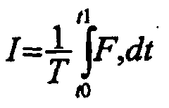
- Une prothèse selon la revendication 31, caractérisée par le fait que le circuit de traitement (24) est agencé pour générer un indice de rampe I, oùet T est la période du pas ou durée de la phase d'appui, t0 et t1 sont le début et la fin d'une période de mesurage représentant au moins la majeure partie de la phase d'appui, et F est un paramètre détecté en relation avec ledit moment de fléchissement, et dans laquelle le signal de commande de descente est généré lorsque I est supérieur à la valeur seuil enregistrée.
- Une prothèse selon la revendication 4, caractérisée par le fait que le dispositif de commande de la flexion du genou (18) comprend un ensemble piston et cylindre possédant une chambre (18F) contenant du fluide hydraulique et par le fait que le volume de la chambre varie en fonction du degré de flexion du genou et par le fait que la chambre dispose d'un moyen de dérivation associé situé de telle façon que la résistance au mouvement de l'ensemble piston et cylindre due au fluide hydraulique est non significative sur une plage supérieure de flexion angulaire du genou par rapport à la résistance de l'ensemble due au fluide hydraulique à l'intérieur de ladite partie initiale de la plage angulaire de flexion partant de l'extension complète.
- Une prothèse selon la revendication 33, caractérisée par le fait que le moyen de dérivation comprend un élargissement du cylindre sur une partie de la course du piston.
- Un système de commande adaptatif pour une prothèse de membre inférieur destinée à un amputé au-dessus du genou, comprenant un dispositif de commande de flexion de genou (18) pour résister à la flexion au niveau de l'articulation de genou par des moyens hydrauliques, au minimum un dispositif de détection (26A, 26B, 28) pour générer des signaux électriques de détection en réponse à la mise en charge de la prothèse et un circuit électronique de traitement (24) couplé électriquement au dispositif de détection ou à chaque dispositif de détection et au dispositif de commande pour ajuster automatiquement la résistance hydraulique à la flexion du genou, caractérisé par le fait que le dispositif de commande (18) est agencé pour résister à la flexion de l'articulation de genou par des moyens pneumatiques en plus des moyens hydrauliques et par le fait que le circuit de traitement (24) est agencé pour ajuster la résistance hydraulique et pneumatique à la flexion du genou selon les actions de l'amputé.
- Un système selon la revendication 35, caractérisé par le fait que le circuit de traitement (24) peut fonctionner sur un mode programme et sur un mode de fonctionnement automatique, le système comprenant en outre une unité de commande (50) pouvant être commandée à distance permettant la programmation du système sur ledit mode programme, le dispositif de commande (18) incluant des moyens de commande (54) pour augmenter ou diminuer par incréments la résistance hydraulique à la flexion en temps réel pendant des essais d'activité.
- Un système selon la revendication 35, caractérisé par le fait que le dispositif ou les dispositifs de détection (26A, 26B, 28) sont agencés pour détecter des forces et/ou des mouvements au niveau du genou de la prothèse, le circuit de traitement (24) étant agencé pour détecter le mode d'activité de l'amputé en réponse à des signaux générés par le détecteur ou le dispositif ou les dispositifs.
- Un système selon la revendication 37, caractérisé par le fait que le circuit de traitement (24) est agencé pour détecter au minimum soit la descente d'un plan incliné, soit une condition de trébuchement.
- Un système selon la revendication 38, caractérisé par le fait que le dispositif ou les dispositifs de détection comprennent un détecteur (28) pour produire un signal représentatif du moment de fléchissement du genou et par le fait que le circuit de traitement (24) est agencé pour produire un signal de contrôle de descente par reconnaissance d'une configuration de signaux en provenance dudit détecteur apparaissant pendant la phase d'appui, laquelle configuration est associée à la descente d'un plan incliné.
- Un système selon la revendication 39, caractérisé par le fait que la reconnaissance de la configuration de signaux comprend la comparaison de l'intégrale normalisée du moment de fléchissement du genou obtenue sur au moins une partie de la phase d'appui à une valeur seuil.
- Un système selon la revendication 38, caractérisé par le fait que le dispositif ou les dispositifs de détection comprennent un détecteur de l'angle de flexion du genou (26A, 26B) pour produire un signal électrique représentatif de l'angle de flexion du genou et par le fait que le circuit de traitement (24) est agencé pour produire un signal de mode de trébuchement lorsque ledit signal indique une période d'extension anormalement courte du genou.
- Un système selon la revendication 38, caractérisé par le fait que le dispositif ou les dispositifs de détection comprennent un détecteur de l'angle de flexion du genou (26A, 26B) pour produire un signal électrique représentatif de l'angle de flexion du genou et par le fait que le circuit de traitement (24) est agencé pour produire un signal de mode de trébuchement lorsque ledit signal indique un gradient positif de l'angle de flexion du genou à la suite d'un gradient négatif de l'angle de flexion du genou pendant un état de flexion du genou.
- Un système selon la revendication 38, caractérisé par le fait que le dispositif ou les dispositifs de détection comprennent un détecteur de l'angle de flexion du genou (26A, 26B) pour produire un signal électrique représentatif de l'angle de flexion du genou et par le fait que le circuit de traitement (24) est agencé pour produire un signal de mode de trébuchement lorsque ledit signal indique un angle de flexion anormalement croissant pendant la phase d'appui.
- Un système selon la revendication 38, caractérisé par le fait que le dispositif ou les dispositifs de détection comprennent un détecteur de l'angle de flexion du genou (26A, 26B) pour produire un signal électrique représentatif de l'angle de flexion du genou et par le fait que le circuit de traitement (24) est agencé pour produire un signal de descente d'escalier lorsque ledit signal est représentatif d'une flexion maximale plus élevée du genou et/ou d'une période de flexion du genou plus longue que normal pendant la marche.
Applications Claiming Priority (5)
| Application Number | Priority Date | Filing Date | Title |
|---|---|---|---|
| GBGB9717380.1A GB9717380D0 (en) | 1997-08-15 | 1997-08-15 | A lower limb prosthesis |
| GB9717380 | 1997-08-15 | ||
| GB9813904 | 1998-06-26 | ||
| GBGB9813904.1A GB9813904D0 (en) | 1997-08-15 | 1998-06-26 | A lower limb prosthesis |
| PCT/GB1998/002438 WO1999008621A2 (fr) | 1997-08-15 | 1998-08-13 | Prothese d'un membre inferieur |
Publications (2)
| Publication Number | Publication Date |
|---|---|
| EP1003442A2 EP1003442A2 (fr) | 2000-05-31 |
| EP1003442B1 true EP1003442B1 (fr) | 2003-05-21 |
Family
ID=26312076
Family Applications (1)
| Application Number | Title | Priority Date | Filing Date |
|---|---|---|---|
| EP98938813A Expired - Lifetime EP1003442B1 (fr) | 1997-08-15 | 1998-08-13 | Prothese d'un membre inferieur |
Country Status (9)
| Country | Link |
|---|---|
| US (1) | US6517585B1 (fr) |
| EP (1) | EP1003442B1 (fr) |
| JP (1) | JP2001514925A (fr) |
| AT (1) | ATE240693T1 (fr) |
| AU (1) | AU8741298A (fr) |
| CA (1) | CA2300103A1 (fr) |
| DE (1) | DE69814871T2 (fr) |
| GB (2) | GB9813904D0 (fr) |
| WO (1) | WO1999008621A2 (fr) |
Cited By (1)
| Publication number | Priority date | Publication date | Assignee | Title |
|---|---|---|---|---|
| DE102015010221A1 (de) | 2014-09-05 | 2016-03-10 | Carl Haasper | Kniegelenk-Endoprothese |
Families Citing this family (114)
| Publication number | Priority date | Publication date | Assignee | Title |
|---|---|---|---|---|
| US6113642A (en) | 1996-06-27 | 2000-09-05 | Mauch, Inc. | Computer controlled hydraulic resistance device for a prosthesis and other apparatus |
| GB2338653A (en) * | 1998-06-26 | 1999-12-29 | Blatchford & Sons Ltd | A lower limb prosthesis |
| DE10000781A1 (de) * | 2000-01-11 | 2001-11-29 | Biedermann Motech Gmbh | Vorrichtung und Verfahren zur Fernwartung einer elektronisch ansteuerbaren Prothese |
| ATE300929T1 (de) | 2000-01-20 | 2005-08-15 | Massachusetts Inst Technology | Elektronisch gesteuerte kniegelenkprothese |
| WO2001072245A2 (fr) * | 2000-03-29 | 2001-10-04 | Massachusetts Institute Of Technology | Prothese de genou adaptable a la vitesse et adaptable au patient |
| US6673117B1 (en) * | 2000-11-30 | 2004-01-06 | Adam Soss | Single axis knee joint assembly |
| AU2003236750B2 (en) | 2002-08-22 | 2006-08-10 | Victhom Human Bionics Inc. | Actuated leg prosthesis for above-knee amputees |
| US7736394B2 (en) * | 2002-08-22 | 2010-06-15 | Victhom Human Bionics Inc. | Actuated prosthesis for amputees |
| US6911050B2 (en) * | 2002-10-23 | 2005-06-28 | Joseph L. Molino | Prosthetic knee unit |
| DE10307328A1 (de) * | 2003-02-17 | 2004-09-02 | Eska Implants Gmbh & Co. | Beinprothese |
| GB2399503B (en) * | 2003-03-20 | 2006-03-29 | Blatchford & Sons Ltd | Prosthetic knee joint mechanism |
| US7101487B2 (en) | 2003-05-02 | 2006-09-05 | Ossur Engineering, Inc. | Magnetorheological fluid compositions and prosthetic knees utilizing same |
| US7198071B2 (en) | 2003-05-02 | 2007-04-03 | Össur Engineering, Inc. | Systems and methods of loading fluid in a prosthetic knee |
| US6852131B1 (en) * | 2003-08-18 | 2005-02-08 | Chien-Liang Chen | Artificial knee joint with a push rod biased to rotate a prosthetic lower leg rapidly to align with a residual thigh |
| SE526430C2 (sv) * | 2003-10-17 | 2005-09-13 | Oessur Hf | Artificiell fleraxlig knäled |
| US20050107889A1 (en) | 2003-11-18 | 2005-05-19 | Stephane Bedard | Instrumented prosthetic foot |
| US7815689B2 (en) | 2003-11-18 | 2010-10-19 | Victhom Human Bionics Inc. | Instrumented prosthetic foot |
| US7087090B2 (en) * | 2003-11-19 | 2006-08-08 | Bloorview Macmillan Centre | Artificial knee joint |
| US7431737B2 (en) | 2004-02-12 | 2008-10-07 | össur hf. | System and method for motion-controlled foot unit |
| US20060184280A1 (en) * | 2005-02-16 | 2006-08-17 | Magnus Oddsson | System and method of synchronizing mechatronic devices |
| US7637959B2 (en) | 2004-02-12 | 2009-12-29 | össur hf | Systems and methods for adjusting the angle of a prosthetic ankle based on a measured surface angle |
| EP1734909B1 (fr) | 2004-03-10 | 2013-06-12 | Össur hf | Systeme de commande pour un genou prothetique |
| US7455696B2 (en) | 2004-05-07 | 2008-11-25 | össur hf | Dynamic seals for a prosthetic knee |
| DE202004008014U1 (de) * | 2004-05-18 | 2004-09-09 | Teko Automation, Mensch Und Technik Gmbh | Schwungphasensteuervorrichtung |
| DE202004008024U1 (de) * | 2004-05-19 | 2005-10-06 | Bauerfeind Ag | Regelbarer Bewegungsdämpfer |
| WO2006069264A1 (fr) | 2004-12-22 | 2006-06-29 | össur hf | Systemes et procedes de traitement du mouvement de membre |
| EP1843724B1 (fr) | 2005-02-02 | 2018-07-25 | Össur hf | Systemes et procedes de detection pour la surveillance de la dynamique de marche |
| WO2006084219A2 (fr) | 2005-02-02 | 2006-08-10 | össur hf | Systemes prothetiques et orthopediques destines a la reeducation |
| US8801802B2 (en) * | 2005-02-16 | 2014-08-12 | össur hf | System and method for data communication with a mechatronic device |
| SE528516C2 (sv) * | 2005-04-19 | 2006-12-05 | Lisa Gramnaes | Kombinerat aktivt och passivt benprotessystem samt en metod för att utföra en rörelsecykel med ett sådant system |
| US8016892B2 (en) * | 2005-06-10 | 2011-09-13 | The Ohio Willow Wood Company | Prosthetic device utilizing electric vacuum pump |
| US7655050B2 (en) * | 2005-07-29 | 2010-02-02 | Freedom Innovations, Llc | Computer controlled prosthetic knee device |
| US8299634B2 (en) * | 2005-08-10 | 2012-10-30 | Bionic Power Inc. | Methods and apparatus for harvesting biomechanical energy |
| US7485152B2 (en) * | 2005-08-26 | 2009-02-03 | The Ohio Willow Wood Company | Prosthetic leg having electronically controlled prosthetic knee with regenerative braking feature |
| US8048172B2 (en) | 2005-09-01 | 2011-11-01 | össur hf | Actuator assembly for prosthetic or orthotic joint |
| US7531006B2 (en) * | 2005-09-01 | 2009-05-12 | össur hf | Sensing system and method for motion-controlled foot unit |
| CN101453964B (zh) | 2005-09-01 | 2013-06-12 | 奥瑟Hf公司 | 用于确定地形转换的系统和方法 |
| US8641780B2 (en) | 2005-11-14 | 2014-02-04 | Blatchford Products Limited | Adjustment device for a lower limb prosthesis |
| WO2007110585A2 (fr) * | 2006-03-24 | 2007-10-04 | Chas. A. Blalchford & Sons Limited | Prothese pour membre inferieur et module de commande associe |
| DE102006021802A1 (de) | 2006-05-09 | 2007-11-15 | Otto Bock Healthcare Ip Gmbh & Co. Kg | Steuerung eines passiven Prothesenkniegelenkes mit verstellbarer Dämpfung |
| TWM302355U (en) * | 2006-06-09 | 2006-12-11 | Jia-Bau Jeng | Fixation and cushion structure of knee joint |
| US8771370B2 (en) | 2006-12-13 | 2014-07-08 | Otto Bock Healthcare Gmbh | Orthopedic device |
| GB0701662D0 (en) * | 2006-12-14 | 2007-03-07 | Blatchford & Sons Ltd | A lower limb prosthesis |
| US7985265B2 (en) * | 2006-12-14 | 2011-07-26 | Chas. A. Blatchford & Sons Limited | Prosthetic ankle and foot combination |
| US8435309B2 (en) | 2007-01-05 | 2013-05-07 | Victhom Human Bionics | Joint actuation mechanism for a prosthetic and/or orthotic device having a compliant transmission |
| US8211042B2 (en) * | 2007-01-05 | 2012-07-03 | Victom Human Bionics Inc. | High torque active mechanism for orthotic and/or prosthetic devices |
| US9808357B2 (en) | 2007-01-19 | 2017-11-07 | Victhom Laboratory Inc. | Reactive layer control system for prosthetic and orthotic devices |
| JP5122164B2 (ja) * | 2007-03-13 | 2013-01-16 | 株式会社長崎かなえ | 義足 |
| DE102007032090B4 (de) * | 2007-07-09 | 2016-08-11 | Otto Bock Healthcare Gmbh | Orthopädietechnischer Fluiddämpfer |
| DE102007053389A1 (de) | 2007-11-07 | 2009-05-20 | Otto Bock Healthcare Ip Gmbh & Co. | Verfahren zur Steuerung eines orthopädischen Gelenkes |
| US8628585B2 (en) | 2007-12-14 | 2014-01-14 | Blatchford Products Limited | Lower limb prosthesis |
| US20090234456A1 (en) * | 2008-03-14 | 2009-09-17 | Warsaw Orthopedic, Inc. | Intervertebral Implant and Methods of Implantation and Treatment |
| EP2257247B1 (fr) | 2008-03-24 | 2018-04-25 | Ossur HF | Systemes de prothese transfemorales et procedes de fonctionnement des systemes |
| US8974543B2 (en) * | 2008-04-30 | 2015-03-10 | Rizzoli Ortopedia S.P.A. | Automatic prosthesis for above-knee amputees |
| DE102008024747A1 (de) | 2008-05-20 | 2009-12-03 | Otto Bock Healthcare Products Gmbh | Orthopädische Einrichtung mit einem Gelenk sowie Verfahren zur Steuerung einer orthopädischen Einrichtung |
| US9351855B2 (en) | 2008-06-16 | 2016-05-31 | Ekso Bionics, Inc. | Powered lower extremity orthotic and method of operation |
| WO2010005473A1 (fr) * | 2008-06-16 | 2010-01-14 | Berkeley Bionics | Prothèse transfémorale semi-actionnée de genou |
| US8685093B2 (en) * | 2009-01-23 | 2014-04-01 | Warsaw Orthopedic, Inc. | Methods and systems for diagnosing, treating, or tracking spinal disorders |
| US8126736B2 (en) * | 2009-01-23 | 2012-02-28 | Warsaw Orthopedic, Inc. | Methods and systems for diagnosing, treating, or tracking spinal disorders |
| US8128699B2 (en) * | 2009-03-13 | 2012-03-06 | Warsaw Orthopedic, Inc. | Spinal implant and methods of implantation and treatment |
| US9017418B2 (en) * | 2009-05-05 | 2015-04-28 | össur hf | Control systems and methods for prosthetic or orthotic devices |
| US9387096B2 (en) * | 2009-06-17 | 2016-07-12 | Ossur Hf | Feedback control systems and methods for prosthetic or orthotic devices |
| US8598815B2 (en) * | 2009-06-22 | 2013-12-03 | University Of Washington Through Its Center For Commercialization | Controllable transverse rotation adaptor |
| US8449623B2 (en) * | 2009-09-18 | 2013-05-28 | Orthocare Innovations Llc | Self-aligning prosthesis with hydraulic actuators |
| US8801803B2 (en) | 2009-11-30 | 2014-08-12 | Korea Workers' Compensation & Welfare Service | Connection structure of artificial limb and socket, using magnetic locking device |
| CA2789594A1 (fr) * | 2010-02-12 | 2011-08-18 | Freedom Innovations, L.L.C. | Dispositif et procede de mesure d'angle |
| EP2621414B1 (fr) | 2010-09-29 | 2019-03-13 | Össur HF | Dispositifs prosthétiques et orthétiques et procédés et systèmes pour commander ceux-ci |
| TWI439947B (zh) * | 2010-11-11 | 2014-06-01 | Ind Tech Res Inst | 辨識人體移動行為之方法及系統 |
| US9060884B2 (en) | 2011-05-03 | 2015-06-23 | Victhom Human Bionics Inc. | Impedance simulating motion controller for orthotic and prosthetic applications |
| US8736087B2 (en) | 2011-09-01 | 2014-05-27 | Bionic Power Inc. | Methods and apparatus for control of biomechanical energy harvesting |
| US9532877B2 (en) | 2011-11-11 | 2017-01-03 | Springactive, Inc. | Robotic device and method of using a parallel mechanism |
| US10543109B2 (en) | 2011-11-11 | 2020-01-28 | Össur Iceland Ehf | Prosthetic device and method with compliant linking member and actuating linking member |
| GB201121437D0 (en) * | 2011-12-13 | 2012-01-25 | Blatchford & Sons Ltd | A lower limb prothesis |
| US9017419B1 (en) | 2012-03-09 | 2015-04-28 | össur hf | Linear actuator |
| JP5465365B1 (ja) * | 2012-03-09 | 2014-04-09 | ナブテスコ株式会社 | 多節リンク膝継手 |
| US9044346B2 (en) | 2012-03-29 | 2015-06-02 | össur hf | Powered prosthetic hip joint |
| TWM444158U (zh) * | 2012-04-05 | 2013-01-01 | Pro Limb Internat Corp | 免調整之多段式義肢氣壓缸及其多段式氣壓閥 |
| US10918501B2 (en) | 2012-04-05 | 2021-02-16 | Pro Limb International Corp. | Polycentric knee joint having an adjustment-free multi-stage air cylinder |
| WO2013172968A1 (fr) * | 2012-05-15 | 2013-11-21 | Vanderbilt University | Commande de montée et de descente d'escaliers pour dispositifs de membre inférieur motorisés |
| US8928161B2 (en) | 2012-05-25 | 2015-01-06 | Kcf Technologies, Inc. | Apparatuses and methods for harvesting energy from prosthetic limbs |
| GB201213035D0 (en) | 2012-07-23 | 2012-09-05 | Blatchford Products Ltd | A lower limb prosthesis |
| WO2014039885A1 (fr) * | 2012-09-06 | 2014-03-13 | Freedom Innovations, Llc | Procédé et système pour un dispositif prosthétique avec des niveaux multiples de fonctionnalité activés par des systèmes de commande multiples |
| EP2928419B1 (fr) * | 2012-12-06 | 2017-10-25 | Centri Ab | Prothèse d'articulation de genou |
| US9561118B2 (en) | 2013-02-26 | 2017-02-07 | össur hf | Prosthetic foot with enhanced stability and elastic energy return |
| US9028557B2 (en) | 2013-03-14 | 2015-05-12 | Freedom Innovations, Llc | Prosthetic with voice coil valve |
| EP2967920B1 (fr) | 2013-03-14 | 2021-04-21 | Ossur Hf | Prothèse de cheville et méthode de contrôle appropriée, fondée sur l'adaptation à la vitesse |
| US9763809B2 (en) | 2013-08-27 | 2017-09-19 | Freedom Innovations, Llc | Microprocessor controlled prosthetic ankle system for footwear and terrain adaptation |
| US12144748B2 (en) | 2013-08-27 | 2024-11-19 | Proteor USA, LLC | Microprocessor controlled prosthetic ankle system for footwear and terrain adaptation |
| CN106456339B (zh) | 2014-04-11 | 2020-02-07 | 奥索有限责任公司 | 具有可去除柔性构件的义肢脚 |
| DE102015100876B4 (de) * | 2014-12-16 | 2016-08-11 | medi prosthetics GmbH | Hydraulischer Dämpfungszylinder, insbesondere für ein Prothesenkniegelenk |
| GB2536056B (en) | 2015-03-06 | 2017-07-12 | Blatchford Products Ltd | Lower Limb Prosthesis |
| GB201504242D0 (en) | 2015-03-13 | 2015-04-29 | Boender Jacob Q L And Boender Jennifer A | Improvements in or relating to prosthetic joints |
| NL2014674B1 (en) * | 2015-04-20 | 2017-01-20 | Univ Delft Tech | Energy storing prosthetic knee actuator. |
| JP6400530B2 (ja) * | 2015-06-19 | 2018-10-03 | ナブテスコ株式会社 | 義足膝継手およびその制御方法 |
| US9949850B2 (en) | 2015-09-18 | 2018-04-24 | Össur Iceland Ehf | Magnetic locking mechanism for prosthetic or orthotic joints |
| US10195099B2 (en) | 2016-01-11 | 2019-02-05 | Bionic Power Inc. | Method and system for intermittently assisting body motion |
| CN105769395B (zh) * | 2016-04-12 | 2017-07-18 | 上海理工大学 | 用于智能膝关节的电控液压阻尼缸结构 |
| US10253855B2 (en) | 2016-12-15 | 2019-04-09 | Boston Dynamics, Inc. | Screw actuator for a legged robot |
| DE102017000902A1 (de) * | 2017-02-01 | 2018-08-02 | Rhefor Gbr (Vertretungsberechtigter Gesellschafter: Arno Mecklenburg, 10999 Berlin) | Elektromagnetisches Verriegelungselement für eine Gelenk-Orthese oder Gelenk-Prothese |
| RU176146U1 (ru) * | 2017-04-26 | 2018-01-09 | федеральное государственное бюджетное образовательное учреждение высшего образования "Уфимский государственный авиационный технический университет" | Мехатронный протез сустава |
| DE102018111234B3 (de) * | 2018-05-09 | 2019-08-29 | Otto Bock Healthcare Products Gmbh | Orthopädisches Hilfsmittel |
| GB2576372B (en) | 2018-08-17 | 2023-02-01 | Blatchford Products Ltd | Lower limb prosthesis |
| CN110169850B (zh) * | 2019-05-17 | 2020-07-17 | 上海理工大学 | 被动型液压膝关节假肢的控制方法 |
| CN114206272B (zh) * | 2019-07-30 | 2025-04-01 | 科里居帕克工业有限公司 | 在过度伸展处具有阻力变化机构的液压假肢膝关节 |
| WO2021055851A1 (fr) | 2019-09-18 | 2021-03-25 | Össur Iceland Ehf | Procédés et systèmes de commande d'un dispositif prothétique ou orthétique |
| WO2021154184A1 (fr) * | 2020-01-27 | 2021-08-05 | Proted Protez Ortez Ve Rehabilitasyon Ltd. Sti. | Actionneur hydraulique pour commander la vitesse de flexion et d'extension d'une articulation prothétique du genou |
| DE102020004338B4 (de) * | 2020-07-20 | 2022-11-03 | Otto Bock Healthcare Products Gmbh | Verfahren zur Steuerung einer Prothese oder Orthese |
| CN112353534B (zh) * | 2020-10-28 | 2023-09-12 | 北京工道风行智能技术有限公司 | 一种智能液压电机混合驱动膝关节装置 |
| US20220202594A1 (en) * | 2020-12-25 | 2022-06-30 | Nabtesco Corporation | Prosthetic knee joint |
| CN113520681B (zh) * | 2021-07-14 | 2024-05-03 | 北京汇凡商贸有限公司 | 一种基于人机工程学的机械式关节辅助医疗器械 |
| CN115701796B (zh) | 2021-07-21 | 2025-09-16 | 香港中文大学 | 一种用于人体下肢外骨骼、假肢、矫形器的智能膝关节 |
| CN114732575B (zh) * | 2022-04-15 | 2024-09-20 | 上海理工大学 | 一种离断式连杆髋关节动力假肢 |
| KR102981603B1 (ko) | 2024-03-18 | 2026-06-24 | 한국기계연구원 | 강성제어가 가능한 의족 시스템 및 이의 구동방법 |
| DE102024110270A1 (de) | 2024-04-12 | 2025-10-16 | Otto Bock Healthcare Products Gmbh | Verfahren zur Steuerung eines künstlichen Kniegelenks |
Family Cites Families (10)
| Publication number | Priority date | Publication date | Assignee | Title |
|---|---|---|---|---|
| US4212087A (en) * | 1978-11-16 | 1980-07-15 | Mortensen Lavaugh L | Prosthetic leg with a hydraulic control |
| US5062856A (en) | 1988-03-25 | 1991-11-05 | Kabushiki Kaisha Kobe Seiko Sho | Teaching playback swing-phase-controlled above-knee prosthesis |
| US5092902A (en) * | 1990-08-16 | 1992-03-03 | Mauch Laboratories, Inc. | Hydraulic control unit for prosthetic leg |
| GB9105464D0 (en) * | 1991-03-14 | 1991-05-01 | Blatchford & Sons Ltd | An artificial leg |
| FR2677540A1 (fr) | 1991-06-14 | 1992-12-18 | Migeon Christian | Articulation de prothese orthopedique a verin hydraupneumatique et blocage de flexion electromagnetique. |
| CA2057108C (fr) | 1991-12-05 | 1996-12-31 | Kelvin B. James | Systeme pour controler l'action d'une articulation artificielle du genou dans une prothese femorale |
| US5405409A (en) * | 1992-12-21 | 1995-04-11 | Knoth; Donald E. | Hydraulic control unit for prosthetic leg |
| GB9312131D0 (en) * | 1993-06-11 | 1993-07-28 | Blatchford & Sons Ltd | Prosthesis control system |
| GB2280609B (en) | 1993-06-11 | 1997-10-08 | Blatchford & Sons Ltd | Prosthesis control system |
| US5888212A (en) * | 1997-06-26 | 1999-03-30 | Mauch, Inc. | Computer controlled hydraulic resistance device for a prosthesis and other apparatus |
-
1998
- 1998-06-26 GB GBGB9813904.1A patent/GB9813904D0/en active Pending
- 1998-08-13 EP EP98938813A patent/EP1003442B1/fr not_active Expired - Lifetime
- 1998-08-13 CA CA002300103A patent/CA2300103A1/fr not_active Abandoned
- 1998-08-13 AU AU87412/98A patent/AU8741298A/en not_active Abandoned
- 1998-08-13 GB GB9817689A patent/GB2328160B/en not_active Expired - Lifetime
- 1998-08-13 US US09/485,800 patent/US6517585B1/en not_active Expired - Lifetime
- 1998-08-13 DE DE69814871T patent/DE69814871T2/de not_active Expired - Lifetime
- 1998-08-13 JP JP2000509366A patent/JP2001514925A/ja active Pending
- 1998-08-13 AT AT98938813T patent/ATE240693T1/de active
- 1998-08-13 WO PCT/GB1998/002438 patent/WO1999008621A2/fr not_active Ceased
Cited By (2)
| Publication number | Priority date | Publication date | Assignee | Title |
|---|---|---|---|---|
| DE102015010221A1 (de) | 2014-09-05 | 2016-03-10 | Carl Haasper | Kniegelenk-Endoprothese |
| DE102015010221B4 (de) * | 2014-09-05 | 2017-11-16 | Carl Haasper | Kniegelenk-Endoprothese |
Also Published As
| Publication number | Publication date |
|---|---|
| GB9817689D0 (en) | 1998-10-07 |
| DE69814871T2 (de) | 2004-02-19 |
| JP2001514925A (ja) | 2001-09-18 |
| US6517585B1 (en) | 2003-02-11 |
| WO1999008621A2 (fr) | 1999-02-25 |
| EP1003442A2 (fr) | 2000-05-31 |
| GB2328160A (en) | 1999-02-17 |
| ATE240693T1 (de) | 2003-06-15 |
| DE69814871D1 (de) | 2003-06-26 |
| GB9813904D0 (en) | 1998-08-26 |
| GB2328160B (en) | 2002-07-03 |
| CA2300103A1 (fr) | 1999-02-25 |
| AU8741298A (en) | 1999-03-08 |
| WO1999008621A3 (fr) | 1999-05-14 |
Similar Documents
| Publication | Publication Date | Title |
|---|---|---|
| US6517585B1 (en) | Lower limb prosthesis | |
| GB2367753A (en) | A lower limb prosthesis | |
| EP1059898B1 (fr) | Prothese d'un membre inferieur et unite de commande | |
| EP1880694B1 (fr) | Système d'articulation prothétique régulable | |
| EP0549855B1 (fr) | Systeme pour commander le mouvement d'une articulation artificielle du genou pour une prothèse de la jambe | |
| EP1998723B1 (fr) | Prothese pour membre inferieur et module de commande associe | |
| USRE39961E1 (en) | Computer controlled hydraulic resistance device for a prosthesis and other apparatus | |
| AU2001249759A1 (en) | Speed-adaptive and patient-adaptive prosthetic knee | |
| US5888212A (en) | Computer controlled hydraulic resistance device for a prosthesis and other apparatus | |
| US6755870B1 (en) | Leg prosthesis with an artificial knee joint and method for controlling a leg prosthesis | |
| WO2001017466A2 (fr) | Prothese pour membre inferieur | |
| WO2000027318A1 (fr) | Dispositif de resistance hydraulique commande par ordinateur pour une prothese et autre appareil connexe | |
| WO1999000075A1 (fr) | Dispositif a resistance hydraulique commande par ordinateur pour prothese ou autre appareil | |
| CN117679222A (zh) | 假腿坐立模式控制方法、控制装置及智能假腿 |
Legal Events
| Date | Code | Title | Description |
|---|---|---|---|
| PUAI | Public reference made under article 153(3) epc to a published international application that has entered the european phase |
Free format text: ORIGINAL CODE: 0009012 |
|
| 17P | Request for examination filed |
Effective date: 20000302 |
|
| AK | Designated contracting states |
Kind code of ref document: A2 Designated state(s): AT DE FR SE |
|
| 17Q | First examination report despatched |
Effective date: 20010102 |
|
| GRAG | Despatch of communication of intention to grant |
Free format text: ORIGINAL CODE: EPIDOS AGRA |
|
| GRAG | Despatch of communication of intention to grant |
Free format text: ORIGINAL CODE: EPIDOS AGRA |
|
| GRAG | Despatch of communication of intention to grant |
Free format text: ORIGINAL CODE: EPIDOS AGRA |
|
| GRAH | Despatch of communication of intention to grant a patent |
Free format text: ORIGINAL CODE: EPIDOS IGRA |
|
| GRAH | Despatch of communication of intention to grant a patent |
Free format text: ORIGINAL CODE: EPIDOS IGRA |
|
| GRAA | (expected) grant |
Free format text: ORIGINAL CODE: 0009210 |
|
| AK | Designated contracting states |
Designated state(s): AT DE FR SE |
|
| REF | Corresponds to: |
Ref document number: 69814871 Country of ref document: DE Date of ref document: 20030626 Kind code of ref document: P |
|
| REG | Reference to a national code |
Ref country code: SE Ref legal event code: TRGR |
|
| ET | Fr: translation filed | ||
| PLBE | No opposition filed within time limit |
Free format text: ORIGINAL CODE: 0009261 |
|
| STAA | Information on the status of an ep patent application or granted ep patent |
Free format text: STATUS: NO OPPOSITION FILED WITHIN TIME LIMIT |
|
| 26N | No opposition filed |
Effective date: 20040224 |
|
| REG | Reference to a national code |
Ref country code: DE Ref legal event code: R082 Ref document number: 69814871 Country of ref document: DE Representative=s name: ISARPATENT, DE |
|
| REG | Reference to a national code |
Ref country code: DE Ref legal event code: R082 Ref document number: 69814871 Country of ref document: DE Representative=s name: ISARPATENT - PATENTANWAELTE- UND RECHTSANWAELT, DE Effective date: 20120808 Ref country code: DE Ref legal event code: R082 Ref document number: 69814871 Country of ref document: DE Representative=s name: ISARPATENT PATENTANWAELTE BEHNISCH, BARTH, CHA, DE Effective date: 20120808 Ref country code: DE Ref legal event code: R082 Ref document number: 69814871 Country of ref document: DE Representative=s name: ISARPATENT, DE Effective date: 20120808 Ref country code: DE Ref legal event code: R081 Ref document number: 69814871 Country of ref document: DE Owner name: BLATCHFORD PRODUCTS LTD., BASINGSTOKE, GB Free format text: FORMER OWNER: CHAS A BLATCHFORD & SONS LTD., BASINGSTOKE, HAMPSHIRE, GB Effective date: 20120808 Ref country code: DE Ref legal event code: R081 Ref document number: 69814871 Country of ref document: DE Owner name: BLATCHFORD PRODUCTS LTD., GB Free format text: FORMER OWNER: CHAS A BLATCHFORD & SONS LTD., BASINGSTOKE, GB Effective date: 20120808 |
|
| REG | Reference to a national code |
Ref country code: FR Ref legal event code: TP Owner name: BLATCHFORD PRODUCTS LIMITED, GB Effective date: 20120905 |
|
| REG | Reference to a national code |
Ref country code: AT Ref legal event code: PC Ref document number: 240693 Country of ref document: AT Kind code of ref document: T Owner name: BLATCHFORD PRODUCTS LIMITED, GB Effective date: 20130723 |
|
| REG | Reference to a national code |
Ref country code: FR Ref legal event code: PLFP Year of fee payment: 18 |
|
| REG | Reference to a national code |
Ref country code: FR Ref legal event code: PLFP Year of fee payment: 19 |
|
| PGFP | Annual fee paid to national office [announced via postgrant information from national office to epo] |
Ref country code: DE Payment date: 20160822 Year of fee payment: 19 |
|
| PGFP | Annual fee paid to national office [announced via postgrant information from national office to epo] |
Ref country code: SE Payment date: 20160819 Year of fee payment: 19 Ref country code: AT Payment date: 20160822 Year of fee payment: 19 Ref country code: FR Payment date: 20160822 Year of fee payment: 19 |
|
| REG | Reference to a national code |
Ref country code: DE Ref legal event code: R119 Ref document number: 69814871 Country of ref document: DE |
|
| REG | Reference to a national code |
Ref country code: AT Ref legal event code: MM01 Ref document number: 240693 Country of ref document: AT Kind code of ref document: T Effective date: 20170813 |
|
| PG25 | Lapsed in a contracting state [announced via postgrant information from national office to epo] |
Ref country code: SE Free format text: LAPSE BECAUSE OF NON-PAYMENT OF DUE FEES Effective date: 20170814 |
|
| REG | Reference to a national code |
Ref country code: FR Ref legal event code: ST Effective date: 20180430 |
|
| PG25 | Lapsed in a contracting state [announced via postgrant information from national office to epo] |
Ref country code: AT Free format text: LAPSE BECAUSE OF NON-PAYMENT OF DUE FEES Effective date: 20170813 |
|
| PG25 | Lapsed in a contracting state [announced via postgrant information from national office to epo] |
Ref country code: DE Free format text: LAPSE BECAUSE OF NON-PAYMENT OF DUE FEES Effective date: 20180301 |
|
| PG25 | Lapsed in a contracting state [announced via postgrant information from national office to epo] |
Ref country code: FR Free format text: LAPSE BECAUSE OF NON-PAYMENT OF DUE FEES Effective date: 20170831 |