EP1003594B1 - Schlittschuh mit flexiblem fussbett - Google Patents
Schlittschuh mit flexiblem fussbett Download PDFInfo
- Publication number
- EP1003594B1 EP1003594B1 EP98916719A EP98916719A EP1003594B1 EP 1003594 B1 EP1003594 B1 EP 1003594B1 EP 98916719 A EP98916719 A EP 98916719A EP 98916719 A EP98916719 A EP 98916719A EP 1003594 B1 EP1003594 B1 EP 1003594B1
- Authority
- EP
- European Patent Office
- Prior art keywords
- cuff
- portions
- heel
- skate
- posterior
- Prior art date
- Legal status (The legal status is an assumption and is not a legal conclusion. Google has not performed a legal analysis and makes no representation as to the accuracy of the status listed.)
- Expired - Lifetime
Links
Images









Classifications
-
- A—HUMAN NECESSITIES
- A43—FOOTWEAR
- A43B—CHARACTERISTIC FEATURES OF FOOTWEAR; PARTS OF FOOTWEAR
- A43B5/00—Footwear for sporting purposes
- A43B5/16—Skating boots
- A43B5/1641—Skating boots characterised by the sole ; characterised by the attachment of the skate
-
- A—HUMAN NECESSITIES
- A63—SPORTS; GAMES; AMUSEMENTS
- A63C—SKATES; SKIS; ROLLER SKATES; DESIGN OR LAYOUT OF COURTS, RINKS OR THE LIKE
- A63C1/00—Skates
- A63C1/22—Skates with special foot-plates of the boot
- A63C1/28—Pivotally-mounted plates
Definitions
- Conventional skates whether they are ice skates or in-line (wheeled) skates, generally include a boot and a blade or wheels rigidly attached to the bottom of the boot by way of a frame (i.e. a blade frame or a wheel frame, as the case may be).
- the boot includes an upper portion for supporting a skater's ankle and foot, and a substantially flat footbed or sole for supporting the sole of a skater's foot.
- the upper portion of the boot while quite rigid, allows a small amount of forward flex (i.e. forward ankle pivot, moving a skater's lower knee forward relative to the footbed), without which a skater would not be able to bend his or her knees significantly without falling backwards.
- a second object of the invention is to provide a more comfortable skate, designed to accommodate and facilitate the natural anatomy and physiology of the foot.
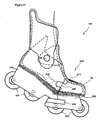
- a skate comprising: a boot comprising a footbed for supporting the sole of a foot and an upper portion for supporting a lower leg: the footbed comprising anterior and posterior portions and first hinge means therebetween to permit upward pivotal movement of the anterior and posterior portions of the footbed relative to each other between first and second positions; the upper portion comprising anterior and posterior portions movable relative to each other, the anterior portion of the upper portion of the boot being rigidly attached to the anterior portion of the footbed, and the posterior portion of the upper portion of the boot being rigidly attached to the posterior portion of the footbed; the posterior portion of the upper portion of the boot comprising a cuff portion, a heel portion, and a second hinge means attached to the cuff and heel to permit backward and forward pivotal movement of the cuff and heel relative to each other; and slidably interlocking interfaces between the cuff and heel portions to allow biomechanically efficient relative movement, while ensuring adequate support; and blade means comprising anterior and posterior portions depending
- the boot 12 includes an upper portion 15 for supporting the lower leg, ankle and foot 5, and a footbed 20 for supporting the sole of the skater's foot.
- the footbed 20 includes an anterior portion 25 and a posterior portion 30.
- a first hinge 35 is attached between the anterior portion 25 of the footbed 20 and the posterior portion 30 of the footbed 20.
- the first hinge 35 may be variously constructed. For example, it may be a conventional door-type hinge having two separate rigid components and a pin. Alternatively, the first hinge 35 may simply be a flexible zone of the footbed 20. Alternatively, the first hinge 35 may be a complex hinge. The first hinge 35 permits upward pivotal movement of the anterior portion 25 of the footbed 20 and the posterior portion 30 of the footbed 20 relative to each other between a first position, illustrated in Figure 1, and a second position, illustrated in Figures 2 and 3.
- the anterior portion 40 of the ice skate blade means 13 and the anterior connective means 85 have a posterior face 50
- the posterior portion 45 of the ice skate blade means 13 and the posterior connective means 90 have an anterior face 55.
- the posterior face 50 and the anterior face 55 come into contact when the ice skate 10 is in the first position.
- Figures 1, 2, 3, 5, 6 and 7 illustrate that in this configuration, the posterior connective means 90 overlaps the anterior connective means 85 in a tongue in groove fashion (where the anterior connective means 85 is the tongue and the posterior connective means 90 is the groove) .
- the other overlapping sections such as those in the boot, this restricts lateral flexibility, thus providing support for the skater's foot and ankle.
- Figure 7 illustrates that the interface between the anterior connective means 85 and the posterior connective means 90 is 'V' shaped to further ensure that as the skate returns to its upright position, the posterior portion 45 of the blade means is brought into correct alignment with the anterior portion 40 of the blade means.
- Alternative configurations for example with the anterior connective means 85, overlapping the posterior connective means 90 (where the posterior becomes the tongue and the anterior the groove), are merely optional manifestations of the same principles.
- the upper portion 15 of the boot 12 includes an anterior portion 60 and a posterior portion 65.
- the anterior portion 60 of the boot 12 is rigidly attached to the anterior portion 25 of the footbed 20.
- the posterior portion 65 of the boot 12 is rigidly attached to the posterior portion 30 of the footbed 20.
- the first hinge 35 therefore enables the anterior portion 60 and the posterior portion 65 to pivot relative to each other. Limiting the point beyond which such forward flex is restricted is effected by way of stop means 57.
- stop means can be variously constructed and located and may include adjustment means in which to tailor the skate function to suit the skater's needs.
- the posterior portion 65 of the boot 12 includes a cuff portion 70 and a heel portion 75, and an overlapping central portion 95.
- This central portion 95 may consist of one or more overlapping or interlocking sections, and may be variously constructed.
- a second hinge 80 functioning over and with the skater's ankle, adjoins the cuff portion 70, the heel portion 75, and the overlapping section(s) 95.
- This hinge means 80 permits backward and forward pivotal movement of the cuff portion 70 and the heel portion 75 relative to each other.
- the second hinge 80 may be variously constructed.
- the overlapping central portion(s) 95 provides lateral support and protection while allowing full calf muscle extension.
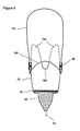
- Figure 4 illustrates the design of the cuff portion 70 and the heel portion 75 of the posterior portion 45 of the upper portion 15 of the boot 12.
- the cuff portion 70 includes an upwardly extending arch 100 to permit the cuff portion 70 to rotate towards the backward position without contacting the heel portion 75 prematurely.
- the heel portion 75 also includes a downwardly extending notch 105 and upwardly extending fingers 106 to facilitate flex in the heel portion 75. This notch 105 accommodates the cuff (posterior) pivoting backward from the ankle, as the skate moves toward the second position.
- the ice skate 10 When in use by a skater on an ice surface, the ice skate 10 operates as follows. Upright/gliding position: When the skater's weight is positioned centrally, as in an upright or gliding position, the skate 10 is in the first position, as illustrated in Figure 1. In the first position, both the anterior portion 40 and the posterior portion 45 of the ice skate blade means 13 can be in contact with the ice surface. The angle of contact, and the proportion of anterior 40 and posterior 45 portions in contact with the ice surface depends upon the skater's weight placement, and the positioning and amount of "rocker" (curvature) incorporated into the blades.
- "rocker" curvature
- skate's mid-flex ability over that of a conventional skate's single and rigid blade is that the contact area can be lengthened to provide greater stability. Such is not possible with conventional skates without an implicit disadvantage in stride mechanics and maneuverability. Additionally, the present invention enables the relative distance to the foremost point of the anterior blade 40 to be lengthened (moved forward), to gain mechanical advantage during the final stages of each skating stride.
- Skate thrust/striding During the initial portion of a forward skating stride, the skater begins a weight transition, shifting weight both forward and laterally, off of the striding (or pushing) skate, and onto the gliding skate. In this transition, the skater pushes the striding skate outward, away from that skate's inside edge. As the stride is initiated, the skater's weight on the striding skate shifts forward onto the anterior portion 40, and the hinge means 35 between the anterior and posterior portions of the skate allows the footbed to flex, thereby pivoting the posterior portion 45 off the skating surface, and the skate begins to flex into the second position as illustrated in Figures 2 and 3.
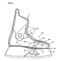
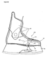
- Figures 8 to 13 illustrate how slidably interlocking interface 200 allows the anterior portion 60 and the posterior portion 65 to pivot relative to each other.
- the slidably interlocking interface 200 allows for biomechanically efficient relative movement, while ensuring that adequate support is provided to the skater.
- the slidably interlocking interface 200 includes upper posterior projections 210 that slide into upper anterior sleeves 220.
- the slidably interlocking interface 200 also includes lateral posterior sleeves 230 that receive lateral anterior projections 240.
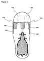
- a complex hinge 250 includes an anterior hinge 260, a posterior hinge 270 and a floating link 280 therebetween. Note that there could be more than one floating link and more than two hinges. Note that the complex hinge 250 is located such that it is posterior to the joint of the ball of the foot of a skater. Figure 10 illustrates the complex hinge 250 in further detail. Hinge pins 290 pass through holes in projections 300 adding strength and rigidity. The complex hinge 250 provides good lateral stability, and is also incorporated into the footbed 20 so that there is no gap between the anterior portion 25 and the posterior portion 30.
- Figure 14 illustrates the movement of the footbed 20, including the complex hinge 250, and the foot of a skater.
- the natural pivot at the ball of the foot takes place at the joint between the distal end of the metatarsals and the proximal end of the phalanges.
- the primary pivot point (that of the great toe) is typically 1.5 to 2 cm above the sole of the foot. Taking into account the thickness of a skate liner and sole, any sub-sole hinge would necessarily displace this pivot point by approximately 2.5 cm. This displacement implies eccentricity with respect to the pivot; the natural foot arc would be somewhat opposed by that imposed by the hinge. The greater the eccentricity, the greater the restriction of function.
- the invention offers a number of alternative solutions to these problems.
- First is the slidably interlocking components of each of the moulded sections.
- Second is the incorporation of torsion resistant hinge means directly into, as opposed to under, the sole. This would offer torsion resistance while greatly reducing the arc differential. It would eliminate any gap in the sole. Its incorporation as part of a moulded skate would offer more elegant and efficient construction and a more durable product. It would allow the inclusion of multiple torsion resistant hinge means to accommodate a full range of flex characteristics.
- Third is the combination of the slidably interlocking components of each of the moulded sections with the torsion resistant hinge means.
Landscapes
- Health & Medical Sciences (AREA)
- General Health & Medical Sciences (AREA)
- Physical Education & Sports Medicine (AREA)
- Footwear And Its Accessory, Manufacturing Method And Apparatuses (AREA)
- Thermotherapy And Cooling Therapy Devices (AREA)
- Socks And Pantyhose (AREA)
Claims (27)
- Schlittschuh (10) aufweisend: einen Schuh (12), welcher aufweist ein Fußbett (20) zum Stützen der Sohle eines Fußes und einen Oberabschnitt (15) zum Stützen eines Knöchelbereiches (5), wobei der Oberabschnitt (15) einen Manschettenabschnitt (70), einen Fersenabschnitt (75), mindestens einen Mittenabschnitt (95), welcher sowohl den Manschettenabschnitt (70) als auch den Fersenabschnitt (75) überlappt, ein Gelenkmittel (80), welches an den Manschettenabschnitt (70), den Fersenabschnitt (75) und den Mittenabschnitt (95) angebracht ist, so dass eine Rück- und Vorwärtsdrehbewegung des Manschettenabschnittes (70), des Fersenabschnittes (75) und des Mittenabschnittes (95) relativ zueinander ermöglicht wird, und verschiebbare ineinandergreifende Grenzflächen (100, 105, 106) zwischen dem Manschettenabschnitt (70) und dem Fersenabschnitt (75), so dass eine biomechanisch wirksame Relativbewegung erlaubt wird, während eine adäquate Stütze sichergestellt ist, und Kuvenmittel (13), welche vom Fußbett (20) starr nach unten ragen.
- Schlittschuh (10) nach Anspruch 1, wobei die verschiebbaren ineinandergreifenden Grenzflächen zwischen dem Manschettenabschnitt (70) und dem Fersenabschnitt (75) einen sich aufwärts erstreckenden Bogen (100) im Manschettenabschnitt (70) aufweisen, so dass dem Manschettenabschnitt (70) ermöglicht wird, sich ohne vorzeitige Kontaktierung mit dem Fersenabschnitt (75) rückwärts zu drehen.
- Schlittschuh (10) nach den Ansprüchen 1 oder 2, wobei die verschiebbaren ineinandergreifenden Grenzflächen zwischen dem Manschettenabschnitt (70) und dem Fersenabschnitt (75) eine sich nach unten erstreckende Aussparung (105) im Fersenabschnitt (75) aufweisen, um den sich rückwärts drehenden Manschettenabschnitt (70) aufzunehmen.
- Schlittschuh (10) aufweisend: einen Schuh (12), welcher aufweist ein Fußbett (20) zum Stützen der Sohle eines Fußes und einen Oberabschnitt (15) zum Stützen eines unteren Beines (5), wobei das Fußbett (20) einen Vorderabschnitt (25) und einen Hinterabschnitt (30) und ein erstes Gelenkmittel (35) dazwischen aufweist, so dass eine Aufwärtsdrehbewegung des Vorderabschnittes (25) und des Hinterabschnittes (30) des Fußbettes (20) relativ zueinander zwischen einem ersten und einem zweiten Abschnitt ermöglicht wird, wobei der Oberabschnitt (15) einen Vorderabschnitt (60) und einen Hinterabschnitt (65) aufweisen, welche relativ zueinander bewegbar sind, wobei der Vorderabschnitt (60) des Oberabschnittes (15) des Schuhs (12) fest an dem Vorderabschnitt (25) des Fußbettes (20) angebracht ist, und der Hinterabschnitt (65) des Oberabschnittes (15) des Schuhs (12) fest an dem Hinterabschnitt (30) des Fußbettes (20) angebracht ist, wobei der Hinterabschnitt (65) des Oberabschnittes (15) des Schuhes (12) aufweist einen Manschettenabschnitt (70), einen Fersenabschnitt (75), mindestens einen Mittenabschnitt (95), welcher sowohl den Manschettenabschnitt (70) als auch den Fersenabschnitt (75) überlappt, ein zweites Gelenkmittel (80), welches an den Manschettenabschnitt (70), den Fersenabschnitt (75) und den Mittenabschnitt (95) angebracht ist, so dass eine Rück- und Vorwärtsdrehbewegung des Manschettenabschnittes (70), des Fersenabschnittes (75) und des Mittenabschnittes (95) relativ zueinander ermöglicht wird, und verschiebbare ineinandergreifende Grenzflächen (100, 105, 106) zwischen dem Manschettenabschnitt (70) und dem Fersenabschnitt (75), so dass eine biomechanisch wirksame Relativbewegung erlaubt wird, während eine adäquate Stütze sichergestellt ist, und Kuvenmittel (13), welche einen Vorderabschnitt (40) und einen Hinterabschnitt (45) aufweisen, welche jeweils vom Vorderabschnitt (25) oder Hinterabschnitt (30) des Fußbettes (20) starr nach unten ragen.
- Schlittschuh (10) nach Anspruch 4, wobei das erste Drehmittel (35) in das Fußbett (20) eingebaut ist und einen Teil des Fußbettes (20) bildet.
- Schlittschuh (10) nach Anspruch 4, wobei das erste Gelenkmittel (35) ein Einzelgelenk ist.
- Schlittschuh (10) nach Anspruch 4, wobei das erste Gelenkmittel (35) ein komplexes Gelenk (250) ist.
- Schlittschuh (10) nach Anspruch 7, wobei das erste Gelenkmittel (35) zwei Gelenke und ein schwimmendes Verbindungsstück (280) aufweist.
- Schlittschuh (10) nach Anspruch 4, wobei die Stelle des ersten Gelenkmittels (35) im Fußbett (20) eine solche ist, dass das erste Gelenkmittel (35) hinter der Verbindungsstelle des Fußballens eines Schlittschuhläufers ist.
- Schlittschuh (10) nach Anspruch 4, welcher ferner Verbindungsmittel (85, 90) aufweist, welche aufweisen eine nach unten ragende Struktur zum festen Verbinden des Vorderabschnittes (40) und des Hinterabschnittes (45) des Kuvenmittels (13) jeweils mit dem Vorderabschnitt (25) oder dem Hinterabschnitt (35) des Fußbettes (20), und ein Ausrichtungsmittel (50, 55), so dass sichergestellt ist, dass sich der Vorderabschnitt (40) und der Hinterabschnitt (45) des Kuvenmittels (13) miteinander ausgerichtet bewegen.
- Schlittschuh (10) nach Anspruch 10, welcher ferner ein Haltemittel (57) aufweist, so dass die Aufwärtsdrehbewegung des Vorderabschnittes (25) und des Hinterabschnittes (30) des Fußbettes (20) relativ zueinander begrenzt ist, wobei durch die Aufwärtsdrehbewegug der Gleithebelarm geändert wird.
- Schlittschuh (10) nach Anspruch 4, welcher ferner verschiebbare ineinandergreifende Grenzflächen (200) zwischen dem Vorderabschnitt (60) und dem Hinterabschnitt (65) des Oberabschnittes (15) des Schuhs (12) aufweist.
- Schlittschuh (10) nach Anspruch 4, wobei die verschiebbaren ineinandergreifenden Grenzflächen zwischen dem Manschettenabschnitt (70) und dem Fersenabschnitt (75) einen sich aufwärts erstreckenden Bogen (100) im Manschettenabschnitt (70) aufweisen, so dass dem Manschettenabschnitt (70) ermöglicht wird, sich ohne vorzeitige Kontaktierung mit dem Fersenabschnitt (75) rückwärts zu drehen.
- Schlittschuh (10) nach den Ansprüchen 4 oder 13, wobei die verschiebbaren ineinandergreifenden Grenzflächen zwischen dem Manschettenabschnitt (70) und dem Fersenabschnitt (75) eine sich nach unten erstreckende Aussparung (105) im Fersenabschnitt (75) aufweisen, um den sich rückwärts drehenden Manschettenabschnitt (70) aufzunehmen.
- Schlittschuh (10) aufweisend: einen Schuh (12), welcher aufweist ein Fußbett (20) zum Stützen der Sohle eines Fußes und einen Oberabschnitt (15) zum Stützen eines Knöchelbereiches (5), wobei der Oberabschnitt (15) einen Manschettenabschnitt (70), einen Fersenabschnitt (75), und ein zweites Gelenkmittel (80), welches an den Manschettenabschnitt (70) und den Fersenabschnitt (75) angebracht ist, so dass eine Rück- und Vorwärtsdrehbewegung des Manschettenabschnittes (70) und des Fersenabschnittes (75) relativ zueinander ermöglicht wird, und verschiebbare ineinandergreifende Grenzflächen zwischen dem Manschettenabschnitt (70) und dem Fersenabschnitt (75), welche einen sich aufwärts erstreckenden Bogen (100) im Manschettenabschnitt (70) aufweisen, so dass dem Manschettenabschnitt (70) ermöglicht wird, sich ohne vorzeitige Kontaktierung mit dem Fersenabschnitt (75) rückwärts zu drehen, womit eine biomechanisch wirksame Relativbewegung erlaubt wird, während eine adäquate Stütze sichergestellt ist, und Kuvenmittel (13), welche vom Fußbett (20) starr nach unten ragen.
- Schlittschuh (10) nach Anspruch 15, wobei die verschiebbaren ineinandergreifenden Grenzflächen zwischen dem Manschettenabschnitt (70) und dem Fersenabschnitt (75) eine sich nach unten erstreckende Aussparung (105) im Fersenabschnitt (75) aufweisen, um den sich rückwärts drehenden Manschettenabschnitt (70) aufzunehmen.
- Schlittschuh (10) aufweisend: einen Schuh (12), welcher aufweist ein Fußbett (20) zum Stützen der Sohle eines Fußes und einen Oberabschnitt (15) zum Stützen eines Knöchelbereiches (5), wobei das Fußbett einen Vorderabschnitt (25) und einen Hinterabschnitt (30) und dazwischen ein erstes Gelenkmittel (35) aufweist, so dass eine Aufwärtsdrehbewegung des Vorderabschnittes (25) und des Hinterabschnittes (30) des Fußbettes relativ zueinander zwischen einer ersten und einer zweiten Position ermöglicht wird, wobei der Oberabschnitt (15) einen Vorderabschnitt (60) und einen Hinterabschnitt (65) aufweisen, welche relativ zueinander bewegbar sind, wobei der Vorderabschnitt (60) des Oberabschnittes (15) des Schuhes (12) starr an dem Vorderabschnitt (25) des Fußbettes (20) angebracht ist, un der Hinterabschnitt (65) des Oberabschnittes (15) des Schuhes (12) fest an dem Hinterabschnitt (30) des Fußbettes (20) angebracht ist, wobei der Hinterabschnitt (65) des Oberabschnittes (15) des Schuhes (12) aufweist einen Manschettenabschnitt (70), einen Fersenabschnitt (75) und ein zweites Gelenkmittel (80), welches an den Manschettenabschnitt (70) und den Fersenabschnitt (75) angebracht ist, so dass eine Rück- und Vorwärtsdrehbewegung des Manschettenabschnittes (70) und des Fersenabschnittes (75) relativ zueinander ermöglicht wird, und verschiebbare ineinandergreifende Grenzflächen (100, 105, 106) zwischen dem Manschettenabschnitt (70) und dem Fersenabschnitt (75), so dass eine biomechanisch wirksame Relativbewegung erlaubt wird, während eine adäquate Stütze sichergestellt ist, und Kuvenmittel (13), welche einen Vorderabschnitt (40) und einen Hinterabschnitt (45) aufweisen, welche jeweils vom Vorderabschnitt (25) oder Hinterabschnitt (30) des Fußbettes (20) starr nach unten ragen.
- Schlittschuh (10) nach Anspruch 17, wobei die verschiebbaren ineinandergreifenden Grenzflächen zwischen dem Manschettenabschnitt (70) und dem Fersenabschnitt (75) einen sich aufwärts erstreckenden Bogen (100) im Manschettenabschnitt (70) aufweisen, so dass dem Manschettenabschnitt (70) ermöglicht wird, sich ohne vorzeitige Kontaktierung mit dem Fersenabschnitt (75) rückwärts zu drehen.
- Schlittschuh (10) nach den Ansprüchen 17 oder 18, wobei die verschiebbaren ineinandergreifenden Grenzflächen zwischen dem Manschettenabschnitt (70) und dem Fersenabschnitt (75) eine sich nach unten erstreckende Aussparung (105) im Fersenabschnitt (75) aufweisen, um den sich rückwärts drehenden Manschettenabschnitt (70) aufzunehmen.
- Schlittschuh (10) nach Anspruch 27, wobei das erste Drehmittel (35) in das Fußbett (20) eingebaut ist und einen Teil des Fußbettes (20) bildet.
- Schlittschuh (10) nach Anspruch 17, wobei das erste Gelenkmittel (35) ein Einzelgelenk ist.
- Schlittschuh (10) nach Anspruch 17, wobei das erste Gelenkmittel (35) ein komplexes Gelenk (250) ist.
- Schlittschuh (10) nach Anspruch 22, wobei das erste Gelenkmittel (35) zwei Gelenke und ein schwimmendes Verbindungsstück (280) aufweist.
- Schlittschuh (10) nach Anspruch 17, wobei die Stelle des ersten Gelenkmittels (35) im Fußbett (20) eine solche ist, dass das erste Gelenkmittel (35) hinter der Verbindungsstelle des Fußballens eines Schlittschuhläufers ist.
- Schlittschuh (10) nach Anspruch 17, welcher ferner Verbindungsmittel (85, 90) aufweist, welche aufweisen eine nach unten ragende Struktur zum festen Verbinden des Vorderabschnittes (40) und des Hinterabschnittes (45) des Kuvenmittels (13) jeweils mit dem Vorderabschnitt (25) oder dem Hinterabschnitt (35) des Fußbettes (20), und ein Ausrichtungsmittel (50, 55), so dass sichergestellt ist, dass sich der Vorderabschnitt (40) und der Hinterabschnitt (45) des Kuvenmittels (13) miteinander ausgerichtet bewegen.
- Schlittschuh (10) nach Anspruch 25, welcher ferner ein Haltemittel (57) aufweist, so dass die Aufwärtsdrehbewegung des Vorderabschnittes (25) und des Hinterabschnittes (30) des Fußbettes (20) relativ zueinander begrenzt ist, wobei durch die Aufwärtsdrehbewegug der Gleithebelarm geändert wird.
- Schlittschuh (10) nach Anspruch 17, welcher ferner verschiebbare ineinandergreifende Grenzflächen (200) zwischen dem Vorderabschnitt (60) und dem Hinterabschnitt (65) des Oberabschnittes (15) des Schuhs (12) aufweist.
Applications Claiming Priority (3)
| Application Number | Priority Date | Filing Date | Title |
|---|---|---|---|
| CA2203331 | 1997-04-22 | ||
| CA002203331A CA2203331C (en) | 1997-04-22 | 1997-04-22 | Flexible footbed skate |
| PCT/CA1998/000370 WO1998047576A1 (en) | 1997-04-22 | 1998-04-22 | Flexible footbed skate |
Publications (2)
| Publication Number | Publication Date |
|---|---|
| EP1003594A1 EP1003594A1 (de) | 2000-05-31 |
| EP1003594B1 true EP1003594B1 (de) | 2003-03-26 |
Family
ID=4160486
Family Applications (1)
| Application Number | Title | Priority Date | Filing Date |
|---|---|---|---|
| EP98916719A Expired - Lifetime EP1003594B1 (de) | 1997-04-22 | 1998-04-22 | Schlittschuh mit flexiblem fussbett |
Country Status (7)
| Country | Link |
|---|---|
| US (1) | US6217036B1 (de) |
| EP (1) | EP1003594B1 (de) |
| AT (1) | ATE235286T1 (de) |
| AU (1) | AU7021598A (de) |
| CA (1) | CA2203331C (de) |
| DE (1) | DE69812642T2 (de) |
| WO (1) | WO1998047576A1 (de) |
Families Citing this family (17)
| Publication number | Priority date | Publication date | Assignee | Title |
|---|---|---|---|---|
| US7419187B2 (en) | 1997-10-24 | 2008-09-02 | K-2 Corporation | Double klap flex base boot with heel linkage |
| US6120040A (en) * | 1997-10-24 | 2000-09-19 | K-2 Corporation | Flexing base skate |
| US6666463B2 (en) | 1997-10-24 | 2003-12-23 | K-2 Corporation | Flexing base skate |
| US6883811B2 (en) * | 1998-06-26 | 2005-04-26 | Juraj George Tlucko | Skate with pivoting front carriage |
| FR2787724A1 (fr) * | 1998-12-24 | 2000-06-30 | Salomon Sa | Patin comprenant une chaussure articulee sur un chassis |
| US6736412B1 (en) | 2000-10-04 | 2004-05-18 | K2 Corporation | Klop skate having pushing and pulling capabilities |
| EP1334755A1 (de) * | 2002-02-08 | 2003-08-13 | Oliver Damm | Komfort-Verbesserung und Dynamisierung von Inline-Skates |
| US7513068B2 (en) * | 2002-05-06 | 2009-04-07 | William Benjamin Fauver | Variable flexion resistance sport boot |
| NL1034382C2 (nl) * | 2007-09-13 | 2009-03-16 | Bouwadvies B B A B V | Hulpmiddel voor atletische sportbeoefening. |
| WO2009049244A1 (en) * | 2007-10-10 | 2009-04-16 | Dasc Skating Llc | Skate boot |
| US20110101665A1 (en) * | 2009-10-30 | 2011-05-05 | Dasc, Llc | Hockey skate |
| US8684368B2 (en) * | 2009-10-30 | 2014-04-01 | Easton Sports, Inc. | Hockey skate |
| US20140042718A1 (en) * | 2012-08-09 | 2014-02-13 | Ajyle Skate LLC | Biomechanical articulating skate |
| US9510639B2 (en) | 2013-03-11 | 2016-12-06 | Bauer Hockey, Inc. | Hockey skate |
| US9878229B2 (en) | 2013-03-11 | 2018-01-30 | Bauer Hockey, Llc | Skate with injected boot form |
| US9004501B2 (en) * | 2013-05-04 | 2015-04-14 | Douglas Pokupec | Ice skate blade assembly |
| US20160242496A1 (en) * | 2015-02-20 | 2016-08-25 | Kelly Barnes | Article of footwear |
Citations (2)
| Publication number | Priority date | Publication date | Assignee | Title |
|---|---|---|---|---|
| EP0353532A1 (de) * | 1988-08-02 | 1990-02-07 | NORDICA S.p.A. | Schalenaufbau für Schischuh |
| US5884420A (en) * | 1996-01-30 | 1999-03-23 | Salomon S.A. | Sport boot |
Family Cites Families (28)
| Publication number | Priority date | Publication date | Assignee | Title |
|---|---|---|---|---|
| US619327A (en) * | 1899-02-14 | Skate-runner | ||
| US31797A (en) * | 1861-03-26 | Improvement in skates | ||
| DE488768C (de) * | 1929-12-31 | Georg Fruehbeis | Gelenk-Schlitt- oder Rollschuh | |
| US454040A (en) * | 1891-06-16 | Skate | ||
| US467047A (en) * | 1892-01-12 | Skate | ||
| US1228544A (en) * | 1916-04-19 | 1917-06-05 | Carl Louis Falstrem | Ice-skate. |
| US1603588A (en) | 1925-04-17 | 1926-10-19 | Eberle Ferdinand | Skate |
| US1751692A (en) * | 1925-12-18 | 1930-03-25 | Fruhbeis Georg | Ice skate |
| US2093915A (en) | 1937-01-27 | 1937-09-21 | Klevstad Edward | Skate |
| CA1167254A (en) * | 1980-08-11 | 1984-05-15 | Hans Martin | Sports shoe or boot |
| CA1244648A (en) | 1985-11-08 | 1988-11-15 | Gaston Schaeffer | Ice skate |
| DE3542251A1 (de) * | 1985-11-29 | 1987-06-04 | Lothar Herbert Haupt | Eislaufschuh |
| US4839972A (en) | 1986-02-28 | 1989-06-20 | Pack Roger N | Footwear with pivotal toe |
| NL8602796A (nl) * | 1986-11-05 | 1988-06-01 | Peter Brinckman | Schaats. |
| US4724627A (en) * | 1986-12-03 | 1988-02-16 | Sff, Inc. | Sports boot for skiers and the like |
| FR2659534B1 (fr) * | 1990-03-16 | 1994-09-23 | Salomon Sa | Ensemble chaussure/patin et chaussure destinee a un tel ensemble. |
| FR2697728B1 (fr) | 1992-11-06 | 1995-01-13 | Salomon Sa | Chaussure destinée à la pratique d'un sport de glisse. |
| CA2084829C (en) | 1992-12-08 | 1999-04-20 | T. Blaine Hoshizaki | Skate boot with moulded plastic overlay |
| US5540455A (en) | 1994-02-23 | 1996-07-30 | Chambers; Lile R. | Articulating skateboard with springable connector |
| IT1273897B (it) | 1994-06-08 | 1997-07-11 | Nordica Spa | Struttura di pattino a rotelle a calzabilita' migliorata |
| US5595392A (en) * | 1995-07-31 | 1997-01-21 | Casillas; Anthony | In-line roller ice skate combination |
| CA2155444A1 (en) * | 1995-08-04 | 1997-02-05 | Raymond Mitchell | Hinged skate |
| FR2740985B1 (fr) | 1995-11-14 | 1997-12-12 | Salomon Sa | Patin a roues en ligne a chassis deformable |
| ES2154778T3 (es) | 1995-12-04 | 2001-04-16 | Benetton Spa | Patin de ruedas en linea. |
| US5957470A (en) | 1996-03-07 | 1999-09-28 | Powell; David A. | Flexible skate |
| US5794362A (en) * | 1996-04-24 | 1998-08-18 | Polk, Iii; Louis F. | Size adjustable athletic boot |
| FR2755584B1 (fr) * | 1996-11-08 | 1999-01-15 | Salomon Sa | Chaussure de sport comportant un collier mobile |
| ITTV980078A1 (it) * | 1998-05-14 | 1999-11-14 | Benetton Sportsystem Spa | Struttura di pattino con ruote in linea |
-
1997
- 1997-04-22 CA CA002203331A patent/CA2203331C/en not_active Expired - Fee Related
-
1998
- 1998-04-22 WO PCT/CA1998/000370 patent/WO1998047576A1/en not_active Ceased
- 1998-04-22 EP EP98916719A patent/EP1003594B1/de not_active Expired - Lifetime
- 1998-04-22 US US09/403,703 patent/US6217036B1/en not_active Expired - Fee Related
- 1998-04-22 DE DE69812642T patent/DE69812642T2/de not_active Expired - Fee Related
- 1998-04-22 AT AT98916719T patent/ATE235286T1/de not_active IP Right Cessation
- 1998-04-22 AU AU70215/98A patent/AU7021598A/en not_active Abandoned
Patent Citations (2)
| Publication number | Priority date | Publication date | Assignee | Title |
|---|---|---|---|---|
| EP0353532A1 (de) * | 1988-08-02 | 1990-02-07 | NORDICA S.p.A. | Schalenaufbau für Schischuh |
| US5884420A (en) * | 1996-01-30 | 1999-03-23 | Salomon S.A. | Sport boot |
Also Published As
| Publication number | Publication date |
|---|---|
| DE69812642T2 (de) | 2004-06-24 |
| CA2203331A1 (en) | 1998-10-22 |
| EP1003594A1 (de) | 2000-05-31 |
| ATE235286T1 (de) | 2003-04-15 |
| AU7021598A (en) | 1998-11-13 |
| CA2203331C (en) | 2006-02-21 |
| US6217036B1 (en) | 2001-04-17 |
| DE69812642D1 (de) | 2003-04-30 |
| WO1998047576A1 (en) | 1998-10-29 |
Similar Documents
| Publication | Publication Date | Title |
|---|---|---|
| EP1003594B1 (de) | Schlittschuh mit flexiblem fussbett | |
| US5664344A (en) | Shoe for the practice of a gliding sport | |
| US20040025374A1 (en) | Sole/support assembly for a boot and a boot incorporating such sole/support assembly | |
| US6442875B1 (en) | Footwear | |
| US6826853B1 (en) | Sports shoe particularly for motocross | |
| JPH01308501A (ja) | 靴用の底部形状 | |
| US20020062579A1 (en) | Sports boot with flexible frame | |
| US6371494B1 (en) | Sports boot with variable rigidity | |
| US5957470A (en) | Flexible skate | |
| PL185994B1 (pl) | But | |
| EP0731654B1 (de) | Schlittschuh | |
| EP2787851B1 (de) | Skischuh | |
| US20050204585A1 (en) | Expandable tongue for articulated boots | |
| US4505057A (en) | Ski boot sole extension | |
| US5933986A (en) | Lateral stability device for sport boot | |
| NO313484B1 (no) | Såle for sportsskotöy | |
| JPH09173101A (ja) | 調節可能な胴部を有する靴 | |
| US6299182B1 (en) | Flexible skate | |
| US20050115116A1 (en) | Article of footwear, binding assembly and article of footwear-binding assembly combination | |
| US20030110664A1 (en) | Sports shoe | |
| CA2335425C (en) | Footwear | |
| KR200200713Y1 (ko) | 중앙바퀴 분리형 롤러브레이드, 롤러스케이트 | |
| EP4593656A1 (de) | Skischuh mit weicher spitze | |
| US20140283414A1 (en) | Inner shoe for a ski boot | |
| JPH0824007A (ja) | スポーツ靴のインナブーツ |
Legal Events
| Date | Code | Title | Description |
|---|---|---|---|
| PUAI | Public reference made under article 153(3) epc to a published international application that has entered the european phase |
Free format text: ORIGINAL CODE: 0009012 |
|
| 17P | Request for examination filed |
Effective date: 19991109 |
|
| AK | Designated contracting states |
Kind code of ref document: A1 Designated state(s): AT BE CH CY DE DK ES FI FR GB GR IE IT LI LU MC NL PT SE |
|
| 17Q | First examination report despatched |
Effective date: 20010502 |
|
| GRAH | Despatch of communication of intention to grant a patent |
Free format text: ORIGINAL CODE: EPIDOS IGRA |
|
| GRAH | Despatch of communication of intention to grant a patent |
Free format text: ORIGINAL CODE: EPIDOS IGRA |
|
| GRAA | (expected) grant |
Free format text: ORIGINAL CODE: 0009210 |
|
| AK | Designated contracting states |
Designated state(s): AT BE CH CY DE DK ES FI FR GB GR IE IT LI LU MC NL PT SE |
|
| PG25 | Lapsed in a contracting state [announced via postgrant information from national office to epo] |
Ref country code: GR Free format text: LAPSE BECAUSE OF FAILURE TO SUBMIT A TRANSLATION OF THE DESCRIPTION OR TO PAY THE FEE WITHIN THE PRESCRIBED TIME-LIMIT Effective date: 20030326 Ref country code: FR Free format text: LAPSE BECAUSE OF FAILURE TO SUBMIT A TRANSLATION OF THE DESCRIPTION OR TO PAY THE FEE WITHIN THE PRESCRIBED TIME-LIMIT Effective date: 20030326 Ref country code: FI Free format text: LAPSE BECAUSE OF FAILURE TO SUBMIT A TRANSLATION OF THE DESCRIPTION OR TO PAY THE FEE WITHIN THE PRESCRIBED TIME-LIMIT Effective date: 20030326 Ref country code: BE Free format text: LAPSE BECAUSE OF FAILURE TO SUBMIT A TRANSLATION OF THE DESCRIPTION OR TO PAY THE FEE WITHIN THE PRESCRIBED TIME-LIMIT Effective date: 20030326 Ref country code: AT Free format text: LAPSE BECAUSE OF FAILURE TO SUBMIT A TRANSLATION OF THE DESCRIPTION OR TO PAY THE FEE WITHIN THE PRESCRIBED TIME-LIMIT Effective date: 20030326 |
|
| REG | Reference to a national code |
Ref country code: GB Ref legal event code: FG4D |
|
| REG | Reference to a national code |
Ref country code: CH Ref legal event code: EP |
|
| PG25 | Lapsed in a contracting state [announced via postgrant information from national office to epo] |
Ref country code: LU Free format text: LAPSE BECAUSE OF NON-PAYMENT OF DUE FEES Effective date: 20030422 Ref country code: IE Free format text: LAPSE BECAUSE OF NON-PAYMENT OF DUE FEES Effective date: 20030422 Ref country code: CY Free format text: LAPSE BECAUSE OF FAILURE TO SUBMIT A TRANSLATION OF THE DESCRIPTION OR TO PAY THE FEE WITHIN THE PRESCRIBED TIME-LIMIT Effective date: 20030422 |
|
| PG25 | Lapsed in a contracting state [announced via postgrant information from national office to epo] |
Ref country code: MC Free format text: LAPSE BECAUSE OF NON-PAYMENT OF DUE FEES Effective date: 20030430 |
|
| REF | Corresponds to: |
Ref document number: 69812642 Country of ref document: DE Date of ref document: 20030430 Kind code of ref document: P |
|
| REG | Reference to a national code |
Ref country code: IE Ref legal event code: FG4D |
|
| PG25 | Lapsed in a contracting state [announced via postgrant information from national office to epo] |
Ref country code: SE Free format text: LAPSE BECAUSE OF FAILURE TO SUBMIT A TRANSLATION OF THE DESCRIPTION OR TO PAY THE FEE WITHIN THE PRESCRIBED TIME-LIMIT Effective date: 20030626 Ref country code: PT Free format text: LAPSE BECAUSE OF FAILURE TO SUBMIT A TRANSLATION OF THE DESCRIPTION OR TO PAY THE FEE WITHIN THE PRESCRIBED TIME-LIMIT Effective date: 20030626 Ref country code: GB Free format text: LAPSE BECAUSE OF NON-PAYMENT OF DUE FEES Effective date: 20030626 Ref country code: DK Free format text: LAPSE BECAUSE OF FAILURE TO SUBMIT A TRANSLATION OF THE DESCRIPTION OR TO PAY THE FEE WITHIN THE PRESCRIBED TIME-LIMIT Effective date: 20030626 |
|
| REG | Reference to a national code |
Ref country code: CH Ref legal event code: NV Representative=s name: ING. HANS LUDESCHER, PATENTABTEILUNG DER SFS GRUPP |
|
| PG25 | Lapsed in a contracting state [announced via postgrant information from national office to epo] |
Ref country code: ES Free format text: LAPSE BECAUSE OF FAILURE TO SUBMIT A TRANSLATION OF THE DESCRIPTION OR TO PAY THE FEE WITHIN THE PRESCRIBED TIME-LIMIT Effective date: 20030930 |
|
| PLBE | No opposition filed within time limit |
Free format text: ORIGINAL CODE: 0009261 |
|
| STAA | Information on the status of an ep patent application or granted ep patent |
Free format text: STATUS: NO OPPOSITION FILED WITHIN TIME LIMIT |
|
| REG | Reference to a national code |
Ref country code: IE Ref legal event code: MM4A |
|
| GBPC | Gb: european patent ceased through non-payment of renewal fee |
Effective date: 20030626 |
|
| EN | Fr: translation not filed | ||
| 26N | No opposition filed |
Effective date: 20031230 |
|
| PGFP | Annual fee paid to national office [announced via postgrant information from national office to epo] |
Ref country code: CH Payment date: 20060426 Year of fee payment: 9 |
|
| PGFP | Annual fee paid to national office [announced via postgrant information from national office to epo] |
Ref country code: NL Payment date: 20060430 Year of fee payment: 9 Ref country code: IT Payment date: 20060430 Year of fee payment: 9 |
|
| PGFP | Annual fee paid to national office [announced via postgrant information from national office to epo] |
Ref country code: DE Payment date: 20060502 Year of fee payment: 9 |
|
| REG | Reference to a national code |
Ref country code: CH Ref legal event code: PCAR Free format text: ISLER & PEDRAZZINI AG;POSTFACH 1772;8027 ZUERICH (CH) |
|
| REG | Reference to a national code |
Ref country code: CH Ref legal event code: PL |
|
| NLV4 | Nl: lapsed or anulled due to non-payment of the annual fee |
Effective date: 20071101 |
|
| PG25 | Lapsed in a contracting state [announced via postgrant information from national office to epo] |
Ref country code: NL Free format text: LAPSE BECAUSE OF NON-PAYMENT OF DUE FEES Effective date: 20071101 Ref country code: DE Free format text: LAPSE BECAUSE OF NON-PAYMENT OF DUE FEES Effective date: 20071101 |
|
| PG25 | Lapsed in a contracting state [announced via postgrant information from national office to epo] |
Ref country code: LI Free format text: LAPSE BECAUSE OF NON-PAYMENT OF DUE FEES Effective date: 20070430 Ref country code: CH Free format text: LAPSE BECAUSE OF NON-PAYMENT OF DUE FEES Effective date: 20070430 |
|
| PG25 | Lapsed in a contracting state [announced via postgrant information from national office to epo] |
Ref country code: IT Free format text: LAPSE BECAUSE OF NON-PAYMENT OF DUE FEES Effective date: 20070422 |