EP1003623B1 - Appareil de soudage a froid, par refoulement multiple - Google Patents
Appareil de soudage a froid, par refoulement multiple Download PDFInfo
- Publication number
- EP1003623B1 EP1003623B1 EP96919935A EP96919935A EP1003623B1 EP 1003623 B1 EP1003623 B1 EP 1003623B1 EP 96919935 A EP96919935 A EP 96919935A EP 96919935 A EP96919935 A EP 96919935A EP 1003623 B1 EP1003623 B1 EP 1003623B1
- Authority
- EP
- European Patent Office
- Prior art keywords
- welding
- blocks
- reciprocable
- cam
- die halves
- Prior art date
- Legal status (The legal status is an assumption and is not a legal conclusion. Google has not performed a legal analysis and makes no representation as to the accuracy of the status listed.)
- Expired - Lifetime
Links
- 238000003466 welding Methods 0.000 title claims abstract description 61
- 230000000694 effects Effects 0.000 claims abstract description 18
- 230000010355 oscillation Effects 0.000 claims abstract description 6
- 230000002040 relaxant effect Effects 0.000 claims description 7
- 238000012163 sequencing technique Methods 0.000 claims description 3
- 238000006073 displacement reaction Methods 0.000 claims description 2
- 230000006835 compression Effects 0.000 description 5
- 238000007906 compression Methods 0.000 description 5
- 230000003534 oscillatory effect Effects 0.000 description 5
- 230000000630 rising effect Effects 0.000 description 5
- 206010013710 Drug interaction Diseases 0.000 description 2
- 230000003993 interaction Effects 0.000 description 2
- 238000006467 substitution reaction Methods 0.000 description 2
- 230000001360 synchronised effect Effects 0.000 description 2
- RYGMFSIKBFXOCR-UHFFFAOYSA-N Copper Chemical compound [Cu] RYGMFSIKBFXOCR-UHFFFAOYSA-N 0.000 description 1
- 239000004411 aluminium Substances 0.000 description 1
- XAGFODPZIPBFFR-UHFFFAOYSA-N aluminium Chemical compound [Al] XAGFODPZIPBFFR-UHFFFAOYSA-N 0.000 description 1
- 229910052782 aluminium Inorganic materials 0.000 description 1
- 230000000712 assembly Effects 0.000 description 1
- 238000000429 assembly Methods 0.000 description 1
- 239000010949 copper Substances 0.000 description 1
- 229910052802 copper Inorganic materials 0.000 description 1
- 239000000463 material Substances 0.000 description 1
- 230000001151 other effect Effects 0.000 description 1
- 238000010008 shearing Methods 0.000 description 1
Images


Classifications
-
- B—PERFORMING OPERATIONS; TRANSPORTING
- B23—MACHINE TOOLS; METAL-WORKING NOT OTHERWISE PROVIDED FOR
- B23K—SOLDERING OR UNSOLDERING; WELDING; CLADDING OR PLATING BY SOLDERING OR WELDING; CUTTING BY APPLYING HEAT LOCALLY, e.g. FLAME CUTTING; WORKING BY LASER BEAM
- B23K20/00—Non-electric welding by applying impact or other pressure, with or without the application of heat, e.g. cladding or plating
- B23K20/02—Non-electric welding by applying impact or other pressure, with or without the application of heat, e.g. cladding or plating by means of a press ; Diffusion bonding
- B23K20/028—Butt welding
Definitions
- This invention relates to multiple upset, cold pressure, welding apparatus according to preamble of claim 1 for effecting butt welds in wire, rod, strip or tubular workpieces.
- WO-A-90/09862 describes such an apparatus capable of effecting successful cold pressure welds in copper wires or rods of up to approximately 10 millimetres diameter and in aluminium wires or rods of up to 19 millimetres in diameter.
- the apparatus is provided with a set of two pairs of die halves mounted on a framework on hydraulically actuated piston and cylinder assemblies.
- the die halves of each pair are relatively radially reciprocable to grip or release an end portion of an associated workpiece and the two pairs of die halves are relatively axially reciprocable by means of a further hydraulically actuated piston and cylinder assembly to effect cold pressure welding together of abutting end portions of the workpieces by way of a multiple upset operation.
- GB-A-728 139 describes an earlier, hand-held, apparatus for fine wire in which two lever arms are actuated manually and are pivoted together to apply clamping and welding pressure to end portions of fine wire workpieces held in jaws carried on a fixed block. Two bench mounted type tools operated by a single, hand-operated lever and having fixed and moving holders for pairs of jaws are also described.
- multiple upset, cold pressure, welding apparatus including a welding die set having two pairs of die halves each formed with a groove providing a bore in a closed position of the respective pairs of die halves for effecting gripping of end portions of first and second workpieces reciprocable between the closed position in which the associated portion of the workpiece is gripped and an open position in which the associated portion of the workpiece is released and also being reciprocable in a direction parallel to the longitudinal axis of the workpieces to apply or relax a welding pressure across abutting faces of the end portions of the workpieces, wherein means for translating a rotary motion to a reciprocating linear motion are connected to a rotary output shaft of a speed reducing gear means in turn connected to an electric drive means, and are connected to reciprocate the die halves.
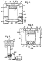
- a multiple upset, cold pressure, welding die set 2 generally such as of the form described in GB-A-728 139 is positioned in a pair of blocks 4 slidingly reciprocable in a housing 6 mounted on a frame (not shown).
- the blocks 4 are provided with pivot connections 8 to lever arms 10, 12 mounted on fulcrum pins 14, 16 on the frame.
- the lever arm 12 carries a high torque, low speed, electric motor 18 and a speed reducing gear box 20 with an output shaft 22 carrying a crank 24.
- a connecting rod 26 is positioned between a crank pin 28 on the crank 24 and connecting pin 30 on the lever arm 10.
- the electric motor 18 is energisable from a mains supply or an independent power pack (not shown).
- end portions of wire workpieces 32 to be butt welded together are positioned within jaws of the die set 2.
- the electric motor 18 is then energised to rotate the crank 24 and to produce an oscillation of the lever arms about the fulcrum pins 14, 16 by virtue of the reciprocatory motion produced by the connecting rod 26 cooperating with the crank 24.
- This produces a reciprocatory movement of the pivot connections 8 and the associated blocks 4 to move the jaws of the die set 2 between gripping and open positions whilst applying or relaxing welding pressure.
- the electric motor 18 is de-energised and the welded wire removed from the die set 2.
- the electric motor 18 is mounted separately on the frame and the connecting rod 26 is positioned between the crank 24 and a central pivot of a pair of toggle links, outer ends of the toggle links being connected respectively to the lever arms 10, 12.
- cam follower rollers 37, 39 are mounted directly on the outer end portions 34, 36 of the lever arms 10, 12 remote from pivot connections 8A to the blocks 4.
- the lever arms are biassed by spring means (not shown) toward each other such that the rollers 37, 39 are biassed into contact with an elliptical cam surface 46A on a cam 48A positioned intermediate the outer end portions 34, 36 and such that rotation of the cam 46A produces an oscillatory movement of the lever arms 10, 12.
- the cam 46A is mounted on an output shaft 22A of a reducing gear box 20A driven from a high torque, low speed, electric motor 18A.
- the multiple upset, cold pressure, butt weld is effected in a manner similar to that described in connection with Figure 1, with energisation of the electric motor 18A effecting rotary movement of the cam 48A as indicated in chain dotted outline.
- the cam follower rollers 37, 39 are biassed into contact with the elliptical cam surface 46A and thus produce an oscillatory movement of the lever arms 10,12.
- the elliptical cam surface 46A is profiled to give a dynamic characteristic to the oscillatory movement appropriate to the multiple upset weld requirements.
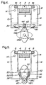
- the lever arms 10, 12 are connected together, at outer end portions 34, 36 remote from pivot connections 8A to the blocks 4, by a pair of toggle links 38, 40 having a central pivot 42.
- the central pivot 42 also carries a cam follower roller 44 co-acting with an elliptical cam surface 46B on a cam 48B mounted on the output shaft 22B of the speed reducing gear box and high torque, low speed, electric motor (not shown in this Figure).
- the multiple upset, cold pressure, butt weld is effected in a manner similar to that described in connection with Figure 1, with energisation of the electric motor effecting rotary movement of the cam 48B as indicated in chain dotted outline.
- the cam follower roller 44 is biassed into contact with the elliptical cam surface 46B and thus produces a reciprocatory motion at the central pivot 42 of the toggle links 38, 40 and hence an oscillatory movement of the lever arms 10, 12.
- the elliptical cam surface 46B is profiled to give a dynamic characteristic to the oscillatory movement appropriate to the multiple upset weld requirements.
- the outer end portions 34, 36 of the lever arms 10, 12 are formed with ramp surfaces 50, 52 and are resiliently biassed toward each other by a spring (not shown).
- Rollers 54, 56 positioned on a wedge 58 co-operate with the ramp surfaces 50, 52 and the wedge 58 is reciprocated on rails (not shown) by inter-action between a cam follower roller 60 on the wedge and an elliptical cam surface 46C on a cam 48C positioned on an output shaft 22C of the speed reducing gear box and the high torque, low speed, electric motor (not shown in this Figure).
- the multiple upset, cold pressure, butt weld is effected in a manner similar to that described in connection with Figure 1, with energisation of the electric motor effecting rotary movement of the cam 48C as indicated in chain dotted outline.
- the reciprocatory motion produced at the cam follower roller 46C during rising and falling portion of the cam cycle produces a reciprocatory motion at the wedge 58.
- the rollers 54, 56 are constrained to ride up the ramps 50, 52 the outer end portions 34, 36 of the lever arms 10, 12 are urged apart.
- the rollers 54, 56 ride down the ramps 50, 52, as indicated in chain dotted outline, and the outer end portions 34, 36 are urged towards each other by the effect of the spring bias.
- the elliptical cam surface 46C is profiled to produce the necessary dynamic characteristics for the multiple upset welding operation.
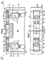
- a multiple upset, cold pressure, welding die set 62 is positioned in a pair of blocks 64 slidingly reciprocable in a housing 66 mounted on a frame 68.
- the blocks 64 are resiliently biassed apart by compression springs (not shown) and have cam following end faces 70 co-acting with elliptical cam surfaces 72 formed on rotary cams 74 mounted on output shafts 76 of speed reducing gear boxes 78 and electric drive motors 80 arranged to be driven in synchronism.
- end portions of workpieces 82 to be butt welded together are positioned within jaws of the die set 62.
- the electric motors 80 are then energised to rotate the cams 74 in unison, as indicated in chain dotted outline, and thus, during a rising portion of the cam cycle, urge the blocks 64 toward each other.
- the compression spring bias acts to urge the blocks away from each other during the falling portion of the cam cycle.
- the electric motors 80 are de-energised and the welded workpiece removed from the die set 62.
- the elliptical cam surfaces 72 are identical and are profiled to produce the necessary dynamic characterisitics for the multiple upset welding operation.
- a sequencing controller (not shown) is arranged to ensure that the electric motors are driven in synchronism.
- end portions of workpieces 82 to be butt welded together are positioned within jaws of the die set 62.
- the electric motors 81 are then energised synchronously to rotate the cams 75 in unison, as indicated in chain dotted outline, and, by virtue of the inter-action between the elliptical cam surfaces 73 and the cam follower rollers 71 to effect lateral displacement of the central pivots 69 of the pairs of toggle links 61, 63 - thereby producing a synchronised reciprocating movement of the blocks 64 to effect multiple upset welding together of the workpiece portions at the die set 62.
- the elliptical cam surfaces 73 are identical and are profiled to produce the necessary dynamic characteristics for the multiple upset welding operation.
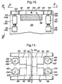
- the arrangement shown in Figures 10, 11, 12 and 13 includes a multiple upset, cold pressure, welding die set 83, generally of the form described in WO-A-90/09862.
- the apparatus includes a frame 84 having mounted thereon, for reciprocable movement, a pair of clamp bodies 86, 88 resiliently biassed apart by compression springs (not shown) and positioned in thrust blocks 90, 92 having cam following end faces 94, 96 co-acting with elliptical cam surfaces 98,100 formed on cams 102, 104 mounted on output shafts 106, 108 of speed reducing gear boxes 110, 112 and electric drive motors 114, 116.
- Further thrust blocks 118 ( Figures 12 and 13) slidingly abut end faces 120 of the clamp bodies 86, 88 and, in turn, have cam following end faces 122 co-acting with elliptical cam surfaces 124 formed on cams 126 mounted on output shafts 128 of speed reducing gear boxes 130 and electric drive motors 132.
- end portions of workpieces 134 to be butt welded together are positioned within the clamp bodies 86, 88.
- Synchronously energising the electric motors 114 moves the clamp bodies 86 to a gripping position during the rising portion of the cycle of the cams 102.
- Synchronously energising the electric motors 116 moves the clamp bodies 88 to a gripping position during the rising portion of the cycle of the cams 104.
- the clamp bodies 86, 88 move to an open position during the falling portions of the cycles of the respective cams 102, 104, as indicated in chain dotted outline, under the influence of compression springs (not shown).
- Synchronously energising the electric motors 132 urges the pairs of the clamp bodies 86, 88 toward each other during the rising portion of the cycle of the cams 126.
- the pairs of clamp bodies 86, 88 are urged apart during the falling portion of the cycle of the cams 126, as indicated in chain dotted outline, by the action of compression springs (not shown). With both pairs of the clamp bodies 86, 88 in the gripping position, moving the pairs toward each other applies welding pressure to the workpiece.
- a sequencing device is utilised to control energisation of the electric motors 114, 116 and 132 in synchronised sequence to effect multiple upset, cold pressure, welding with flash removal intermediate each successive application of welding pressure.
- cam arrangements may be utilised such as utilising the electric motor to provide an intermittent and reversing drive to a suitably profiled cam.
Landscapes
- Engineering & Computer Science (AREA)
- Mechanical Engineering (AREA)
- Pressure Welding/Diffusion-Bonding (AREA)
- Press Drives And Press Lines (AREA)
- Resistance Welding (AREA)
- Fuel-Injection Apparatus (AREA)
- Pharmaceuticals Containing Other Organic And Inorganic Compounds (AREA)
- Wire Processing (AREA)
Claims (10)
- Appareil de soudage à froid par refoulement multiple, comprenant un ensemble de moulage de soudage (2, 62, 83) comportant deux paires de demi-moules formées chacune avec une rainure fournissant un alésage dans une position fermée des paires respectives de demi-moules pour effectuer une préhension de parties d'extrémité de première et seconde pièces de fabrication (32, 82, 34, 134) pouvant se déplacer en va-et-vient entre la position fermée dans laquelle la partie associée de la pièce de fabrication est saisie et une position ouverte dans laquelle la partie associée de la pièce de fabrication est relâchée et pouvant également se déplacer en va-et-vient dans une direction parallèle à l'axe longitudinal des pièces de fabrication pour appliquer ou relâcher une pression de soudage sur les faces contiguës des parties d'extrémité des pièces de fabrication, caractérisé en ce qu'un moyen (24, 26, 46A, 46B, 46C, 72, 73, 98, 100, 124) destiné à convertir un mouvement rotatif en un mouvement linéaire alternatif est relié à un arbre de sortie rotatif (22, 22A, 22B, 76, 77, 106, 108, 128) d'un moyen d'engrenages réducteurs de vitesse (20, 20A, 78, 79, 110, 112, 130) relié quant à lui à un moyen d'entraînement électrique (18, 18A, 80, 81, 114, 116, 132) et est relié pour effectuer un mouvement alternatif des demi-moules.
- Appareil de soudage à froid par refoulement multiple selon la revendication 1, caractérisé en ce que les paires de demi-moules de l'ensemble de moulage de soudage (2) sont montées dans une paire de blocs (4) pouvant se déplacer en va-et-vient de manière coulissante dans un logement (6), les blocs (4) étant chacun dotés de raccordements sur pivot (8) à des bras de levier (10, 12) montés sur des pivots (14, 16), l'un des bras de levier (12) portant un moteur d'entraînement électrique (18) à couple élevé et à vitesse faible et une boîte d'engrenages réducteurs de vitesse (20) entraînant un arbre de sortie (22) portant un bras de manivelle (24) et une tige de raccordement (26) est positionnée entre un maneton (28) sur le bras de manivelle (24) et une broche de raccordement (30) sur l'autre bras de levier (10) de sorte que l'activation du moteur électrique (18) entraîne une oscillation des bras de levier (10, 12) autour des pivots (14, 16) et un déplacement en va-et-vient des raccordements sur pivot (8) et des blocs associés (4) afin de déplacer les demi-moules de l'ensemble de moulage de soudage (2) entre la position de préhension et la position ouverte tout en appliquant ou relâchant la pression de soudage.
- Appareil de soudage à froid par refoulement multiple selon la revendication 1, caractérisé en ce qu'une came rotative (48A, 48B, 48C, 74, 75, 102, 104, 126) ayant une surface de came elliptique (46A, 46B, 46C, 72, 73, 98, 100, 124) est montée sur l'arbre de sortie (22, 22A, 22B, 76, 77, 106, 108, 128) d'un moyen d'engrenages réducteurs de vitesse relié à un moyen d'entraînement électrique (22, 22A, 22B, 76, 77, 106, 108, 128), un suiveur de came à déplacement en va-et-vient (37, 39, 44, 60, 70, 71, 94, 96, 122) est élastiquement sollicité pour entrer en contact avec la surface de came elliptique et le suiveur de came à déplacement en va-et vient est relié pour effectuer un déplacement en va-et-vient des demi-moules.
- Appareil de soudage à froid par refoulement multiple selon la revendication 3, caractérisé en ce que les paires de demi-moules de l'ensemble de moulage de soudage (2) sont montées dans une paire de blocs (4) pouvant se déplacer en va-et-vient de manière coulissante dans un logement (6), les blocs (4) étant chacun dotés de raccordements sur pivot (8A) à des bras de levier (10, 12) montés sur des pivots (14, 16) et portant des rouleaux suiveurs de came (37, 39) sur des parties d'extrémité (34, 36) éloignées des raccordements sur pivot (8A), une came (48A) ayant une surface de came elliptique (46A) étant positionnée entre les rouleaux suiveurs de came (37, 39) et un moyen de sollicitation agencé pour pousser les rouleaux suiveurs de came en contact avec la surface de came elliptique (46A), la came (48A) étant montée sur un arbre de sortie (22A) d'une boîte d'engrenages réducteurs de vitesse (20A) entraînée par un moteur électrique (18A) à couple élevé et à vitesse faible de sorte que l'activation du moteur électrique (18A) entraîne une oscillation des bras de levier (10, 12) autour des pivots (14, 16) et un déplacement en va-et-vient des raccordements sur pivot (8A) et des blocs associés (4) pour déplacer les demi-moules de l'ensemble de moulage de soudage (2) entre la position de préhension et la position ouverte tout en appliquant ou relâchant la pression de soudage.
- Appareil de soudage à froid par refoulement multiple selon la revendication 3, caractérisé en ce que les paires de demi-moules de l'ensemble de moulage de soudage (2) sont montées dans une paire de blocs (4) pouvant se déplacer en va-et-vient de manière coulissante dans un logement (6), les blocs (4) étant chacun dotés de raccordements sur pivot (8A) à des bras de levier (10, 12) montés sur des pivots (14, 16) et portant, sur des parties d'extrémité (34, 36) éloignées des raccordements sur pivot (8A), des genouillères (38, 40) reliées ensemble au niveau d'un pivot central (42) portant un rouleau suiveur de came (44) coopérant avec une surface de came elliptique (468) sur une came (48B) montée sur un arbre de sortie (22B) d'une boîte d'engrenages réducteurs de vitesse (20A) entraînée par un moteur électrique (18A) à couple élevé et à faible vitesse de sorte que l'activation du moteur électrique (18A) entraîne une oscillation des bras de levier (10, 12) autour des pivots (14, 16) et ainsi un déplacement en va-et-vient des raccordements sur pivot (8A) et des blocs associés (4) pour déplacer les demi-moules de l'ensemble de moulage de soudage (2) entre la position de préhension et la position ouverte tout en appliquant ou relâchant la pression de soudage.
- Appareil de soudage à froid par refoulement multiple selon la revendication 3, caractérisé en ce que les paires de demi-moules de l'ensemble de moulage de soudage (2) sont montées dans une paire de blocs (4) pouvant se déplacer en va-et-vient de manière coulissante dans un logement (6), les blocs (4) étant chacun dotés de raccordements sur pivot (8) à des bras de levier (10, 12) montés sur des pivots (14, 16) sollicités élastiquement pour aller l'un vers l'autre et formés, au niveau des parties d'extrémité (34, 36) éloignées des raccordements sur pivot (8), de surfaces de rampe (50, 52) agencées pour interagir avec des rouleaux (54, 56) positionnés sur une cale (58), la cale (58) pouvant se déplacer en va-et vient et portant un rouleau suiveur de came (60) coopérant avec une surface de came elliptique (46C) sur une came (48C) montée sur un arbre de sortie (22) d'une boîte d'engrenages réducteurs de vitesse entraînée par un moteur électrique (18) à couple élevé et à faible vitesse et une boîte d'engrenages réducteurs de vitesse (20) entraînant un arbre de sortie (22) portant un bras de manivelle (24) et une tige de raccordement (26) est positionnée entre un maneton (28) sur le bras de manivelle (24) et une broche de raccordement (30) sur l'autre bras de levier (10) de sorte que l'activation du moteur électrique (18) entraîne une oscillation des bras de levier (10, 12) autour des pivots (14, 16) et ainsi un déplacement en va-et-vient des raccordements sur pivot (8) et des blocs associés (4) pour déplacer les demi-moules de l'ensemble de moulage de soudage (2) entre la position de préhension et la position ouverte tout en appliquant ou relâchant la pression de soudage.
- Appareil de soudage à froid par refoulement multiple selon la revendication 3, caractérisé en ce qu'un ensemble de moulage de soudage (62) comprend des paires de demi-moules positionnées dans une paire de blocs (64) pouvant se déplacer en va-et-vient de manière coulissante dans un logement (66) monté sur un cadre (68) avec les blocs (64) éloignés élastiquement et formés respectivement de faces d'extrémité extérieures (70) agencées pour coopérer avec des surfaces de came elliptiques (72) formées sur des cames rotatives (74) montées sur des arbres de sortie de boîtes d'engrenages réducteurs de vitesse associées (78) et des moteurs d'entraînement électriques (80), de sorte que l'activation des moteurs d'entraînement électriques (80) entraîne un déplacement en va-et-vient des blocs (64) afin de déplacer les demi-moules entre la position de préhension et la position ouverte tout en appliquant et relâchant la pression de soudage.
- Appareil de soudage à froid par refoulement multiple selon la revendication 3, caractérisé en ce qu'un ensemble de moulage de soudage (62) comprend une paire de demi-moules positionnée dans une paire de blocs (64) pouvant se déplacer en va-et-vient de manière coulissante dans un logement (66) avec les blocs (64) éloignés élastiquement et reliés respectivement à des paires de genouillères (61, 63) au niveau de pivots de bloc (65), les genouillères étant chacune reliées au cadre (68) au niveau d'un pivot de cadre (67) éloigné du pivot de bloc (65) et chacune ayant un pivot central (69) portant un rouleau suiveur de came (71) agencé pour coopérer avec une surface de came elliptique associée sur une came (75) montée sur un arbre de sortie (77) d'une boîte d'engrenages réducteurs de vitesse (79) et un moteur d'entraînement électrique (81) à couple élevé et à vitesse faible, de sorte que l'activation des moteurs d'entraînement électriques (81) entraîne une rotation des cames (75) et le déplacement des rouleaux suiveurs de came (71) avec les pivots centraux (69) des genouillères (61, 63) pour entraîner le déplacement en va-et-vient des blocs (64) et ainsi déplacer les demi-moules de l'ensemble de moulage (62) entre la position de préhension et la position ouverte tout en appliquant et relâchant la pression de soudage.
- Appareil de soudage à froid par refoulement multiple selon la revendication 1, caractérisé en ce qu'il comporte un ensemble de moulage de soudage (83) comportant deux paires (86, 88) de demi-moules, chacune étant maintenue éloignée et formée avec une rainure fournissant un alésage dans une position fermée des paires respectives de demi-moules pour effectuer la préhension de parties d'extrémité de première et seconde pièces de fabrication (134) pouvant se déplacer en va-et-vient entre la position fermée dans laquelle une partie associée de la pièce de fabrication est saisie et une position ouverte dans laquelle la partie associée de la pièce de fabrication est relâchée et pouvant également se déplacer en va-et-vient dans une direction parallèle à l'axe longitudinal des pièces de fabrication pour appliquer ou relâcher une pression de soudage sur les faces contiguës des parties d'extrémité des pièces de fabrication, et une pluralité de cames rotatives (102, 104) ayant respectivement chacune une surface de came elliptique (98, 100) sont montées chacune sur des arbres de sortie respectifs (106, 108) d'un moyen réducteur de vitesse (110, 112) relié à un moyen d'entraînement électrique (114, 116), les surfaces de came elliptiques respectives (98, 100) coopérant avec des moyens suiveurs de came à déplacement en va-et-vient (94, 96) reliés respectivement sélectivement pour effectuer un déplacement en va-et-vient collectif ou individuel des demi-moules entre une position fermée et une position ouverte, et une autre pluralité de cames rotatives (126) ayant chacune respectivement une surface de came elliptique (124) sont chacune montées sur des arbres de sortie respectifs (128) d'un moyen réducteur de vitesse (130) relié au moyen d'entraînement électrique (132), les surfaces de came elliptiques respectives (124) coopérant avec un moyen suiveur de came à déplacement en va-et-vient (122) relié pour entraîner l'application ou le relâchement de la pression de soudage sur les faces contiguës des parties d'extrémité des pièces de fabrication (134).
- Appareil de soudage à froid par refoulement multiple selon l'une quelconque des revendications précédentes, caractérisé en ce qu'un dispositif de séquençage électrique est prévu pour commander l'activation du moyen d'entraînement électrique (18, 18A, 80, 81, 114, 116, 132) conformément à une séquence prédéterminée.
Applications Claiming Priority (3)
| Application Number | Priority Date | Filing Date | Title |
|---|---|---|---|
| GB9511424 | 1995-06-06 | ||
| GBGB9511424.5A GB9511424D0 (en) | 1995-06-06 | 1995-06-06 | Multiple upset, cold pressure, welding apparatus |
| PCT/GB1996/001289 WO1996039272A1 (fr) | 1995-06-06 | 1996-05-31 | Appareil de soudage a froid, par refoulement multiple |
Publications (2)
| Publication Number | Publication Date |
|---|---|
| EP1003623A1 EP1003623A1 (fr) | 2000-05-31 |
| EP1003623B1 true EP1003623B1 (fr) | 2006-02-08 |
Family
ID=10775598
Family Applications (1)
| Application Number | Title | Priority Date | Filing Date |
|---|---|---|---|
| EP96919935A Expired - Lifetime EP1003623B1 (fr) | 1995-06-06 | 1996-05-31 | Appareil de soudage a froid, par refoulement multiple |
Country Status (8)
| Country | Link |
|---|---|
| EP (1) | EP1003623B1 (fr) |
| AT (1) | ATE317312T1 (fr) |
| AU (1) | AU5829696A (fr) |
| DE (1) | DE69635807T2 (fr) |
| ES (1) | ES2255079T3 (fr) |
| GB (1) | GB9511424D0 (fr) |
| WO (1) | WO1996039272A1 (fr) |
| ZA (1) | ZA964643B (fr) |
Families Citing this family (5)
| Publication number | Priority date | Publication date | Assignee | Title |
|---|---|---|---|---|
| CN103244526A (zh) * | 2012-02-03 | 2013-08-14 | 上海申辰线缆设备有限公司 | 液动冷焊机 |
| CN108608110B (zh) * | 2018-07-17 | 2024-02-27 | 株洲佳邦难熔金属股份有限公司 | 三明治式金属焊接件摩擦焊接工装及方法 |
| CN109202276A (zh) * | 2018-08-02 | 2019-01-15 | 上海申辰线缆设备有限公司 | 一种非接触式冷焊模具中缝的调整限位装置 |
| CN109158798A (zh) * | 2018-08-13 | 2019-01-08 | 上海申辰线缆设备有限公司 | 一种液压冷焊机装置 |
| CN115319258B (zh) * | 2022-08-30 | 2023-10-20 | 保定天威线材制造有限公司 | 一种铜扁线冷压焊接方法及焊接装置 |
Family Cites Families (4)
| Publication number | Priority date | Publication date | Assignee | Title |
|---|---|---|---|---|
| US2891430A (en) * | 1956-12-13 | 1959-06-23 | Western Electric Co | Automatic shearing and coldwelding apparatus |
| US3613984A (en) * | 1969-01-27 | 1971-10-19 | Kelsey Hayes Co | Adjustable gate for butt welding machine |
| GB8415040D0 (en) * | 1984-06-13 | 1984-07-18 | Sherwen Eng Co Ltd | Welding apparatus |
| US4815648A (en) * | 1987-10-26 | 1989-03-28 | Heintz Corporation | Hand-held cold pressure weld device |
-
1995
- 1995-06-06 GB GBGB9511424.5A patent/GB9511424D0/en active Pending
-
1996
- 1996-05-31 AU AU58296/96A patent/AU5829696A/en not_active Abandoned
- 1996-05-31 ES ES96919935T patent/ES2255079T3/es not_active Expired - Lifetime
- 1996-05-31 AT AT96919935T patent/ATE317312T1/de not_active IP Right Cessation
- 1996-05-31 DE DE69635807T patent/DE69635807T2/de not_active Expired - Lifetime
- 1996-05-31 WO PCT/GB1996/001289 patent/WO1996039272A1/fr not_active Ceased
- 1996-05-31 EP EP96919935A patent/EP1003623B1/fr not_active Expired - Lifetime
- 1996-06-05 ZA ZA964643A patent/ZA964643B/xx unknown
Also Published As
| Publication number | Publication date |
|---|---|
| ZA964643B (en) | 1996-12-12 |
| DE69635807D1 (de) | 2006-04-20 |
| DE69635807T2 (de) | 2006-08-17 |
| ES2255079T3 (es) | 2006-06-16 |
| GB9511424D0 (en) | 1995-08-02 |
| EP1003623A1 (fr) | 2000-05-31 |
| AU5829696A (en) | 1996-12-24 |
| ATE317312T1 (de) | 2006-02-15 |
| WO1996039272A1 (fr) | 1996-12-12 |
Similar Documents
| Publication | Publication Date | Title |
|---|---|---|
| US4291732A (en) | Method and apparatus for manufacture of wire truss and sinuous strut therefor | |
| CN1067630C (zh) | 往复式冲压驱动装置 | |
| US2507817A (en) | Method and apparatus for heating and forging elongated metal blanks | |
| EP1003623A1 (fr) | Appareil de soudage a froid, par refoulement multiple | |
| JPH10244413A (ja) | 対状に協働する工具の整直のための方法及び装置 | |
| US3929000A (en) | High-speed short-stroke forging press | |
| EP0413790B1 (fr) | Procede et machine de soudage sous pression a froid | |
| JPH07201444A (ja) | 電気端子アプリケ−タ | |
| JP5246998B2 (ja) | プレス機にバンド状半完成材料を供給する装置 | |
| SU1311607A3 (ru) | Машина дл сварки сопротивлением непрерывно движущихс сеток | |
| US5724847A (en) | Integrated wire feed and draw apparatus | |
| US3570298A (en) | Forging | |
| JPH0231619B2 (fr) | ||
| JPH0957458A (ja) | 溶接部品供給とそのスポット溶接システム | |
| SU1690920A1 (ru) | Клещева подача к гор чештамповочному прессу | |
| CN115319258A (zh) | 一种铜扁线冷压焊接方法及焊接装置 | |
| US3916665A (en) | Spring fabricating machine and method | |
| US2800813A (en) | Method and apparatus for the plastic shaping of metals | |
| US3453856A (en) | Forging apparatus | |
| US2247864A (en) | Stock feeding mechanism for swaging machines | |
| SU1177007A1 (ru) | Устройство дл подачи штучных заготовок в многопозиционный пресс | |
| US4674624A (en) | Feed bar operating device for a transfer press | |
| JP7509089B2 (ja) | 切断加工装置 | |
| SU1074651A1 (ru) | Манипул тор дл переноса заготовок | |
| US501546A (en) | Automatic chain-welding machine |
Legal Events
| Date | Code | Title | Description |
|---|---|---|---|
| PUAI | Public reference made under article 153(3) epc to a published international application that has entered the european phase |
Free format text: ORIGINAL CODE: 0009012 |
|
| 17P | Request for examination filed |
Effective date: 20000403 |
|
| AK | Designated contracting states |
Kind code of ref document: A1 Designated state(s): AT BE CH DE DK ES FI FR GB GR IE IT LI LU MC NL PT SE |
|
| 17Q | First examination report despatched |
Effective date: 20020829 |
|
| RAP1 | Party data changed (applicant data changed or rights of an application transferred) |
Owner name: COLDWELD LIMITED, A BRITISH COMPANY |
|
| GRAP | Despatch of communication of intention to grant a patent |
Free format text: ORIGINAL CODE: EPIDOSNIGR1 |
|
| GRAS | Grant fee paid |
Free format text: ORIGINAL CODE: EPIDOSNIGR3 |
|
| GRAA | (expected) grant |
Free format text: ORIGINAL CODE: 0009210 |
|
| AK | Designated contracting states |
Kind code of ref document: B1 Designated state(s): AT BE CH DE DK ES FI FR GB GR IE IT LI LU MC NL PT SE |
|
| PG25 | Lapsed in a contracting state [announced via postgrant information from national office to epo] |
Ref country code: NL Free format text: LAPSE BECAUSE OF FAILURE TO SUBMIT A TRANSLATION OF THE DESCRIPTION OR TO PAY THE FEE WITHIN THE PRESCRIBED TIME-LIMIT Effective date: 20060208 Ref country code: LI Free format text: LAPSE BECAUSE OF FAILURE TO SUBMIT A TRANSLATION OF THE DESCRIPTION OR TO PAY THE FEE WITHIN THE PRESCRIBED TIME-LIMIT Effective date: 20060208 Ref country code: FI Free format text: LAPSE BECAUSE OF FAILURE TO SUBMIT A TRANSLATION OF THE DESCRIPTION OR TO PAY THE FEE WITHIN THE PRESCRIBED TIME-LIMIT Effective date: 20060208 Ref country code: CH Free format text: LAPSE BECAUSE OF FAILURE TO SUBMIT A TRANSLATION OF THE DESCRIPTION OR TO PAY THE FEE WITHIN THE PRESCRIBED TIME-LIMIT Effective date: 20060208 Ref country code: BE Free format text: LAPSE BECAUSE OF FAILURE TO SUBMIT A TRANSLATION OF THE DESCRIPTION OR TO PAY THE FEE WITHIN THE PRESCRIBED TIME-LIMIT Effective date: 20060208 Ref country code: AT Free format text: LAPSE BECAUSE OF FAILURE TO SUBMIT A TRANSLATION OF THE DESCRIPTION OR TO PAY THE FEE WITHIN THE PRESCRIBED TIME-LIMIT Effective date: 20060208 |
|
| REG | Reference to a national code |
Ref country code: GB Ref legal event code: FG4D |
|
| REG | Reference to a national code |
Ref country code: CH Ref legal event code: EP |
|
| REG | Reference to a national code |
Ref country code: IE Ref legal event code: FG4D |
|
| REF | Corresponds to: |
Ref document number: 69635807 Country of ref document: DE Date of ref document: 20060420 Kind code of ref document: P |
|
| PG25 | Lapsed in a contracting state [announced via postgrant information from national office to epo] |
Ref country code: DK Free format text: LAPSE BECAUSE OF FAILURE TO SUBMIT A TRANSLATION OF THE DESCRIPTION OR TO PAY THE FEE WITHIN THE PRESCRIBED TIME-LIMIT Effective date: 20060508 |
|
| REG | Reference to a national code |
Ref country code: SE Ref legal event code: TRGR |
|
| PG25 | Lapsed in a contracting state [announced via postgrant information from national office to epo] |
Ref country code: MC Free format text: LAPSE BECAUSE OF NON-PAYMENT OF DUE FEES Effective date: 20060531 Ref country code: IE Free format text: LAPSE BECAUSE OF NON-PAYMENT OF DUE FEES Effective date: 20060531 |
|
| REG | Reference to a national code |
Ref country code: ES Ref legal event code: FG2A Ref document number: 2255079 Country of ref document: ES Kind code of ref document: T3 |
|
| NLV1 | Nl: lapsed or annulled due to failure to fulfill the requirements of art. 29p and 29m of the patents act | ||
| PG25 | Lapsed in a contracting state [announced via postgrant information from national office to epo] |
Ref country code: PT Free format text: LAPSE BECAUSE OF FAILURE TO SUBMIT A TRANSLATION OF THE DESCRIPTION OR TO PAY THE FEE WITHIN THE PRESCRIBED TIME-LIMIT Effective date: 20060710 |
|
| REG | Reference to a national code |
Ref country code: CH Ref legal event code: PL |
|
| ET | Fr: translation filed | ||
| PLBE | No opposition filed within time limit |
Free format text: ORIGINAL CODE: 0009261 |
|
| STAA | Information on the status of an ep patent application or granted ep patent |
Free format text: STATUS: NO OPPOSITION FILED WITHIN TIME LIMIT |
|
| 26N | No opposition filed |
Effective date: 20061109 |
|
| PG25 | Lapsed in a contracting state [announced via postgrant information from national office to epo] |
Ref country code: GR Free format text: LAPSE BECAUSE OF FAILURE TO SUBMIT A TRANSLATION OF THE DESCRIPTION OR TO PAY THE FEE WITHIN THE PRESCRIBED TIME-LIMIT Effective date: 20060509 |
|
| PG25 | Lapsed in a contracting state [announced via postgrant information from national office to epo] |
Ref country code: LU Free format text: LAPSE BECAUSE OF NON-PAYMENT OF DUE FEES Effective date: 20060531 |
|
| PGFP | Annual fee paid to national office [announced via postgrant information from national office to epo] |
Ref country code: DE Payment date: 20120530 Year of fee payment: 17 |
|
| PGFP | Annual fee paid to national office [announced via postgrant information from national office to epo] |
Ref country code: GB Payment date: 20120622 Year of fee payment: 17 Ref country code: FR Payment date: 20120426 Year of fee payment: 17 |
|
| PGFP | Annual fee paid to national office [announced via postgrant information from national office to epo] |
Ref country code: IT Payment date: 20120505 Year of fee payment: 17 |
|
| PGFP | Annual fee paid to national office [announced via postgrant information from national office to epo] |
Ref country code: ES Payment date: 20120507 Year of fee payment: 17 |
|
| PGFP | Annual fee paid to national office [announced via postgrant information from national office to epo] |
Ref country code: SE Payment date: 20130524 Year of fee payment: 18 |
|
| GBPC | Gb: european patent ceased through non-payment of renewal fee |
Effective date: 20130531 |
|
| PG25 | Lapsed in a contracting state [announced via postgrant information from national office to epo] |
Ref country code: DE Free format text: LAPSE BECAUSE OF NON-PAYMENT OF DUE FEES Effective date: 20131203 |
|
| REG | Reference to a national code |
Ref country code: DE Ref legal event code: R119 Ref document number: 69635807 Country of ref document: DE Effective date: 20131203 |
|
| PG25 | Lapsed in a contracting state [announced via postgrant information from national office to epo] |
Ref country code: IT Free format text: LAPSE BECAUSE OF NON-PAYMENT OF DUE FEES Effective date: 20130531 |
|
| REG | Reference to a national code |
Ref country code: FR Ref legal event code: ST Effective date: 20140131 |
|
| PG25 | Lapsed in a contracting state [announced via postgrant information from national office to epo] |
Ref country code: GB Free format text: LAPSE BECAUSE OF NON-PAYMENT OF DUE FEES Effective date: 20130531 |
|
| PG25 | Lapsed in a contracting state [announced via postgrant information from national office to epo] |
Ref country code: FR Free format text: LAPSE BECAUSE OF NON-PAYMENT OF DUE FEES Effective date: 20130531 |
|
| REG | Reference to a national code |
Ref country code: ES Ref legal event code: FD2A Effective date: 20140609 |
|
| PG25 | Lapsed in a contracting state [announced via postgrant information from national office to epo] |
Ref country code: ES Free format text: LAPSE BECAUSE OF NON-PAYMENT OF DUE FEES Effective date: 20130601 |
|
| PG25 | Lapsed in a contracting state [announced via postgrant information from national office to epo] |
Ref country code: SE Free format text: LAPSE BECAUSE OF NON-PAYMENT OF DUE FEES Effective date: 20140601 |
|
| REG | Reference to a national code |
Ref country code: SE Ref legal event code: EUG |