EP1003627B1 - Ringschlüssel und nussschlüssel mit anschlagteilen zum verhindern des abrutschens an muttern oder schrauben - Google Patents
Ringschlüssel und nussschlüssel mit anschlagteilen zum verhindern des abrutschens an muttern oder schrauben Download PDFInfo
- Publication number
- EP1003627B1 EP1003627B1 EP98938439A EP98938439A EP1003627B1 EP 1003627 B1 EP1003627 B1 EP 1003627B1 EP 98938439 A EP98938439 A EP 98938439A EP 98938439 A EP98938439 A EP 98938439A EP 1003627 B1 EP1003627 B1 EP 1003627B1
- Authority
- EP
- European Patent Office
- Prior art keywords
- wrench
- fastener
- portions
- stopper portions
- shoulder portions
- Prior art date
- Legal status (The legal status is an assumption and is not a legal conclusion. Google has not performed a legal analysis and makes no representation as to the accuracy of the status listed.)
- Expired - Lifetime
Links
Images

Classifications
-
- B—PERFORMING OPERATIONS; TRANSPORTING
- B25—HAND TOOLS; PORTABLE POWER-DRIVEN TOOLS; MANIPULATORS
- B25B—TOOLS OR BENCH DEVICES NOT OTHERWISE PROVIDED FOR, FOR FASTENING, CONNECTING, DISENGAGING, OR HOLDING
- B25B23/00—Details of, or accessories for, spanners, wrenches, screwdrivers
- B25B23/0071—Abutment for screws or nuts
-
- B—PERFORMING OPERATIONS; TRANSPORTING
- B25—HAND TOOLS; PORTABLE POWER-DRIVEN TOOLS; MANIPULATORS
- B25B—TOOLS OR BENCH DEVICES NOT OTHERWISE PROVIDED FOR, FOR FASTENING, CONNECTING, DISENGAGING, OR HOLDING
- B25B13/00—Spanners; Wrenches
- B25B13/02—Spanners; Wrenches with rigid jaws
- B25B13/04—Spanners; Wrenches with rigid jaws of ring jaw type
Definitions
- the present invention relates generally to wrenches, and more particularly, to multi-point box-end wrenches and socket wrenches that are provided with stopper portions for restricting the passage of fasteners through the wrenches.
- Multi-point box-end wrenches are well known in the art.
- An advantage of multi-point box-end wrenches is that these types of wrenches permit fasteners to pass clearly through.
- a disadvantage of such wrenches is that the retention of the box-end wrench upon a fastener is relatively difficult, particularly when the box-end wrench is used in restricted locations where the fastener is not easily viewed while the user is attempting to rotate the wrench and fastener.
- DE-U1-29706014 ( on which the preamble of claim 1 is based) discloses a box-end wrench which includes fixed projections in each of its corners for preventing a fastener head from passing therethrough.
- a socket wrench is disclosed in US patent 5-782148 which includes projections in alternate corners of the socket wrench so that a fastener head can be held at an intermediate axial position within the socket wrench.
- the fastener head can only pass into the socket wrench until it abuts an end wall therof. The fastener head accordingly can not pass through the socket wrench.
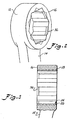
- a box-end wrench 10 is depicted which is constructed in accordance with the principles of the present invention.
- the box-end wrench 10 is usable with conventional hexagonal fasteners or bolts having six corners.
- the wrench 10 includes a head portion 12 formed integrally on one end of a handle 14.
- the handle 14 is preferably offset or angled towards one side thereof as depicted in Fig. 2.
- the head portion 12 has an upper surface 16 and a lower surface 18.
- Inner points 20 are conventionally formed by broaching circumferentially spaced angulated portions 22 with a conventional broaching device. Inner points 20 lie on an inner circumference 24 (Figs. 1a and 3) at the juncture of two angulated portions 22. Outer points 26 are formed by broaching and lie on an outer circumference 28 (Figs. 1a and 3) formed at the junction of two angulated portions 22. As depicted in Figs. 1-3, a 12 point box-end wrench is depicted having 24 angulated portions 22. Two angulated portions 22 forming an inner point 20 define a shoulder portion 30. Two coplanar angulated portions 22 form an imaginary chord 32 therebetween. Two adjacent shoulder portions 30 define triangular areas 34 therebetween.
- integral stopper portions 36 are located in alternating triangular areas 34 between shoulder portions 30 near upper surface 16.
- the stopper portions 36 can be formed by conventional broaching techniques, forging or by welding.
- the stopper.portions 36 are spaced sixty degrees apart.
- the stopper portions 36 act as support structures when the wrench 10 is used upon a nut or bolt head by stopping the axial movement of the wrench 10 in one direction.
- the stopper portions 36 are positioned so as to permit full axial engagement of wrench head 10 with a fastener. Based upon a 12 point wrench, the wrench head 12 will contain six stopper portions 36 positioned in alternating triangular areas 34.
- the stopper portions 36 do not extend beyond chords 32 so as to not interfere with a fastener when the fastener is rotated to another position.
- a stopper portion 36 may substantially fill a triangular area 34 but extends only for a portion of the axial length of the wrench 10.
- the wrench 10 has a first angular position where the stopper portions 36 engage an upper surface of a fastener for restricting the passage of the fastener 25 therethrough.
- a second angular position is reached where the stopper portions 36 do not engage with the upper surface of the fastener thereby permitting the passage of the fastener therethrough.
- the wrench 10 can easily be manipulated to engage the fastener and prevent the wrench 10 from slipping off or past the fastener, or if desired, the wrench 10 can easily be manipulated so that the wrench 10 allows the fastener to pass therethrough.
- a socket wrench 100 is depicted which is similar in all regards to the box-end wrench 10 in structure except that the stopper portions 136 are spaced a vertical distance from a lower surface of the socket so as to enable an ordinary bolt or nut to fit therein.
- Socket wrench 100 is preferably a 12 point deep well socket.
- the wrench 10 of the present invention is useful in manufacturing, assembly and maintenance of mechanical components utilizing two adjacent fasteners.
- the socket wrench 100 of the present invention By using the wrench 10, or, when required, the socket wrench 100 of the present invention, a desired fastener can be selectively and easily accessed, thereby enhancing the ability of mechanics and other wrench users to perform loosening or tightening operations on fasteners that are closely adjacent one another.
- the present wrench 10 and socket wrench 100 according to the invention enhance both industrial efficiency and safety.
Landscapes
- Engineering & Computer Science (AREA)
- Mechanical Engineering (AREA)
- Details Of Spanners, Wrenches, And Screw Drivers And Accessories (AREA)
- Supports Or Holders For Household Use (AREA)
- Mutual Connection Of Rods And Tubes (AREA)
- Lubricants (AREA)
- Transmission Devices (AREA)
Claims (16)
- Ein Schraubenschlüssel zum Drehen eines Befestigungselements, wobei das Befestigungselement eine Anzahl von Kanten an seinem Umfang, eine obere und untere Oberfläche und eine sich axial erstreckende Drehachse aufweist, wobei der Schraubenschlüssel beinhaltet:dadurch gekennzeichnet, dassein Halteteil (12), welches eine Öffnung aufweist, die von einer inneren Fläche definiert wird, die komplementär zu dem Umfang des Befestigungselements ist, wobei das Befestigungselement von dem Halteteil (12) axial aufgenommen werden kann;die innere Oberfläche eine Vielzahl von umfänglich unterteilten Absatzabschnitten (22) definiert, wobei die Absatzabschnitte dazwischen Kanälen bzw. Hohlkehlen (26) definieren, wobei wechselnde Hohlkehlen mit einer korrespondierenden Ecke des Befestigungsmittels in Eingriff gebracht werden können; undAnschlagbereiche (36) in den Hohlkehlen zwischen den Absatzabschnitten (22) angeordnet sind;wobei der Schraubenschlüssel mit dem Befestigungsmittel in einer ersten Winkelpositionen in Eingriff gebracht werden kann, in der die Anschlagbereiche mit einer oberen Fläche des Befestigungsmittels in Eingriff kommen, um einen Durchtritt bzw. ein Durchrutschen des Befestigungsmittels dadurch zu verhindern,
die Anschlagbereiche (36) nur in wechselnden ersten bzw. alternierenden Hohlkehlen zwischen den Absatzabschnitten (22) angeordnet sind, dabei so agiert, die wechselnden ersten Hohlkehlen zu blockieren, während wechselnde zweite Hohlkehlen zwischen den Absatzabschnitten frei von Hindernissen verbleiben;der Schraubenschlüssel mit dem Befestigungsmittel in einer zweiten Winkelpositionen in Eingriff gebracht werden kann, in der die Anschlagbereiche nicht mit der oberen Fläche des Befestigungsmittels in Eingriff kommen und das Befestigungsmittel frei durch die unblockierten zweiten Hohlkehlen des Schraubenschlüssels nach außen hinter das Halteteil (12) passieren kann. - Der Schraubenschlüssel (10) nach Anspruch 1, wobei der Schraubenschlüssel ein geschlossener Zwölfkantringschlüssel ist.
- Der Schraubenschlüssel (100) nach Anspruch 1, wobei der Schraubenschlüssel ein Zwölfkantsteckschlüssel ist.
- der Schraubenschlüssel (10, 100) nach einem der vorangehenden Ansprüche, wobei die innere Fläche durch eine Vielzahl von abwechselnd angeordneten äußeren und inneren Punkten (26, 20) mit dazwischen liegenden Wandbereichen (22) definiert wird, wobei die inneren Punkte (20) auf einem inneren Umfang (24) liegen und die äußeren Punkte (26) auf einem äußeren Umfang (28) liegen und ein dreieckiges Gebiet (34) zwischen zwei benachbarten inneren Punkten (20) und einem äußeren Punkt (26) definieren.
- Der Schraubenschlüssel (10, 100) nach Anspruch 4, wobei jeder der Anschlagbereiche (36, 136) im Wesentlichen eines der dreieckigen Gebiete (34) ausfüllt.
- Der Schraubenschlüssel (10, 100) nach einem der vorangehenden Ansprüche, wobei das Halteteil (12) eine obere und einer untere Fläche (16, 18) besitzt, wobei die Anschlagbereiche (36, 136) benachbart einer der oberen und unteren Fläche (16, 18) angeordnet sind.
- Der Schraubenschlüssel (10, 100) nach Anspruch 4 oder irgendeinem davon abhängenden Anspruch, wobei Profilsehnen (32) durch zwei der Wandbereiche (22) mit zwei dazwischen liegenden Wandbereichen (22) definiert werden.
- Der Schraubenschlüssel (10, 100) nach Anspruch 7, wobei die Anschlagbereiche (36, 136) sich nicht über die Profilsehnen (32) hinauserstrecken.
- Der Schraubenschlüssel (10, 100) nach einem der vorangehenden Ansprüche, worin das Befestigungsmittels eine hexagonale Form aufweist.
- Der Schraubenschlüssel (10, 100) nach einem der vorangehenden Ansprüche, wobei die Anschlagbereiche (36, 136) symmetrisch umfänglich beabstandet sind.
- Der Schraubenschlüssel (10, 100) nach einem der vorangehenden Ansprüche, wobei die Anschlagbereiche (36, 136) integral mit dem Halteteil (12) sind.
- Der Schraubenschlüssel (10, 100) nach einem der vorangehenden Ansprüche, wobei die Vielzahl der Absatzabschnitte (30) eine gerade Anzahl der Absatzabschnitte (30) beinhaltet.
- Ein Verfahren zum Herstellen eines Schraubenschlüssels (10, 100) gemäß einem der vorangehenden Ansprüche, beinhaltend die Schritte:(a) Ausbilden eines Halteteils (12, 100), welches eine Öffnung aufweist, die durch eine innere Fläche definiert wird, definierend eine Vielzahl von umfänglich beabstandeten Absatzabschnitten (30), wobei wechselnde Absatzabschnitte (30) mit Ecken eines Befestigungsmittels in Eingriff gebracht werden können, wobei die Absatzabschnitte (30) Gebiete (34) dazwischen definieren; und(b) Ausbilden von Anschlagbereichen (36, 136), die nur in wechselnden der Gebiete (34) zwischen den Absatzabschnitten (30) angeordnet sind.
- Das Verfahren nach Anspruch 13, wobei die Formschritte mit Hilfe eines Schmiedegesenks durchgeführt werden.
- Das Verfahren nach Anspruch 13, wobei der Schritt (a) mit Hilfe eines Schmiedegesenks durchgeführt wird und Schritt (b) durch Schweißen ausgeführt wird.
- Das Verfahren nach Anspruch 13, worin die Formschritte durch Gebrauch eines Räumwerkzeugs durchgeführt werden.
Applications Claiming Priority (3)
| Application Number | Priority Date | Filing Date | Title |
|---|---|---|---|
| US08/909,624 US5983758A (en) | 1997-08-12 | 1997-08-12 | Box wrench and socket wrench having stopper portions for preventing slippage along a nut or a bolt head |
| US909624 | 1997-08-12 | ||
| PCT/US1998/016429 WO1999007519A1 (en) | 1997-08-12 | 1998-08-06 | Box wrench and socket wrench having stopper portions for preventing slippage along a nut or a bolt head |
Publications (3)
| Publication Number | Publication Date |
|---|---|
| EP1003627A1 EP1003627A1 (de) | 2000-05-31 |
| EP1003627A4 EP1003627A4 (de) | 2001-05-23 |
| EP1003627B1 true EP1003627B1 (de) | 2004-10-20 |
Family
ID=25427568
Family Applications (1)
| Application Number | Title | Priority Date | Filing Date |
|---|---|---|---|
| EP98938439A Expired - Lifetime EP1003627B1 (de) | 1997-08-12 | 1998-08-06 | Ringschlüssel und nussschlüssel mit anschlagteilen zum verhindern des abrutschens an muttern oder schrauben |
Country Status (11)
| Country | Link |
|---|---|
| US (1) | US5983758A (de) |
| EP (1) | EP1003627B1 (de) |
| JP (1) | JP2001513453A (de) |
| CN (1) | CN1139464C (de) |
| AT (1) | ATE280015T1 (de) |
| AU (1) | AU740372B2 (de) |
| BR (1) | BR9815599A (de) |
| CA (1) | CA2300186C (de) |
| DE (1) | DE69827139T2 (de) |
| NZ (1) | NZ502721A (de) |
| WO (1) | WO1999007519A1 (de) |
Cited By (1)
| Publication number | Priority date | Publication date | Assignee | Title |
|---|---|---|---|---|
| DE102008055559A1 (de) | 2008-12-19 | 2010-06-24 | Wera-Werk Hermann Werner Gmbh & Co. Kg | Ring-Maul-Schlüssel |
Families Citing this family (29)
| Publication number | Priority date | Publication date | Assignee | Title |
|---|---|---|---|---|
| US6701768B2 (en) | 2000-06-22 | 2004-03-09 | Hand Tool Design Corporation | Process for making ratchet wheels |
| US20010054334A1 (en) * | 2000-06-22 | 2001-12-27 | David Ling | Spanner with prevention of disengagement of fasteners |
| EP1245339A1 (de) * | 2001-03-28 | 2002-10-02 | Hand Tool Design Corporation | Schlüssel mit Mitteln zur Vermeidung des Heurasspringens von Befestigungselementen |
| US20020166418A1 (en) * | 2001-05-11 | 2002-11-14 | Hsieh Shih Kuei | Wrench capable of avoiding detachment of a screw-thread member |
| US20040099101A1 (en) * | 2002-11-25 | 2004-05-27 | Chih-Ching Hsien | Wrench capable of optionally avoiding detachment of a bolt head member and allowing detachment of the bolt head member |
| US6865971B2 (en) * | 2003-06-25 | 2005-03-15 | Wrench stop | |
| US20050011320A1 (en) * | 2003-07-17 | 2005-01-20 | Chih-Ching Hsien | Wrench having identification function |
| TWI232150B (en) * | 2003-11-18 | 2005-05-11 | Hou-Fei Hu | Improved structure of non-slip wrench |
| US7036227B2 (en) * | 2004-02-06 | 2006-05-02 | David Ling | Process for making ratchet wheels |
| US20060196318A1 (en) * | 2005-03-02 | 2006-09-07 | Teng Chung H | Wrench with end stopper arrangement |
| US7228764B1 (en) * | 2005-12-31 | 2007-06-12 | Proprietary Technologies, Inc. | Maximum engagement wrench |
| DE102007001833B4 (de) * | 2007-01-12 | 2014-08-21 | Krinner Innovation Gmbh | System zur Verankerung eines Mastes, Pfostens oder dergleichen im Erdreich und Verwendung einer Befestigungsvorrichtung und eines Mastes, Pfostens oder dergleichen in einem solchen System |
| FR2911810B1 (fr) * | 2007-01-29 | 2009-08-21 | Peugeot Citroen Automobiles Sa | "embout destine a serrer un ecrou de vehicule" |
| US20090165601A1 (en) * | 2007-12-26 | 2009-07-02 | Jonathan Douglas Bauman | Backup wrench |
| TW201129446A (en) * | 2010-02-26 | 2011-09-01 | Kabo Tool Co | Ratchet flare-nut wrench |
| US8601915B1 (en) | 2011-03-28 | 2013-12-10 | Philip M. Garvey | Wrench stop |
| JP2013000803A (ja) * | 2011-06-13 | 2013-01-07 | Ingu:Kk | レンチ |
| US8739659B2 (en) * | 2012-02-29 | 2014-06-03 | Yu-Tang Chen | Ratchet wrench |
| DE202012100784U1 (de) * | 2012-03-06 | 2012-03-30 | Yu Tang Chen | Ratsche |
| USD794281S1 (en) | 2015-10-09 | 2017-08-15 | Milwaukee Electric Tool Corporation | Garment |
| USD808125S1 (en) | 2015-10-09 | 2018-01-23 | Milwaukee Electric Tool Corporation | Garment |
| CN106002787B (zh) * | 2016-07-18 | 2017-12-22 | 张树国 | 一种智能扭矩套筒 |
| CN110573302B (zh) * | 2017-03-23 | 2021-10-01 | 加固控股有限责任公司 | 多夹持点套筒起子头 |
| KR200491092Y1 (ko) * | 2019-04-17 | 2020-04-07 | 트랜드 주식회사 | 독립형 잠금 툴을 구비하는 기능성 호스 세트 |
| CN112894686A (zh) * | 2021-01-21 | 2021-06-04 | 菲时特集团股份有限公司 | 一种扳手 |
| SE2130347A1 (en) * | 2021-12-08 | 2023-02-21 | Atlas Copco Ind Technique Ab | Socket for power tool, methods of controlling power tools, control systems and power tools |
| GR1010429B (el) * | 2022-05-05 | 2023-03-20 | Θεοδωρος Δημητριου Γλεριδης | Κλειδι για παξιμαδια και μπουλονια διαφορων μεγεθων χωρις κινουμενα μερη |
| TWI857417B (zh) * | 2022-12-12 | 2024-10-01 | 陳公正 | 具止穿效果的扳手 |
| US20240217072A1 (en) * | 2023-01-04 | 2024-07-04 | Yi-Fu Chen | Ratchet ring |
Family Cites Families (11)
| Publication number | Priority date | Publication date | Assignee | Title |
|---|---|---|---|---|
| US2697371A (en) * | 1952-02-29 | 1954-12-21 | Hyman D Bowman | Wrench attachment preventing slippage along nut or bolt head axis |
| US2751802A (en) * | 1953-06-30 | 1956-06-26 | Chauncey R Hatch Jr | Box wrench having a pivotally mounted workpiece abutment |
| US2774259A (en) * | 1955-07-11 | 1956-12-18 | Frank T Caulkins | Method of making box wrenches |
| US3604106A (en) * | 1970-03-27 | 1971-09-14 | Cooper Ind Inc | Fastener retainer |
| US3877327A (en) * | 1973-01-02 | 1975-04-15 | Harold Gustave Erm | Socket wrenches |
| DE2946777C2 (de) * | 1979-11-20 | 1981-12-10 | Hans Mesenhöller KG, 5630 Remscheid | Schraubensteckschlüssel |
| CA1257487A (en) * | 1986-05-13 | 1989-07-18 | Edward Izatt | Box end wrench |
| US5255578A (en) * | 1992-10-29 | 1993-10-26 | Liou Mou Tang | Wrench having a positioning device |
| US5307713A (en) * | 1992-12-18 | 1994-05-03 | White Kenneth L | Self-aligning wrench |
| CA2172570C (en) * | 1996-03-25 | 2004-08-17 | Edward Kerkhoven | Dual depth socket |
| US5865074A (en) * | 1997-03-19 | 1999-02-02 | Hsieh; Chih-Ching | Box end wrench with stop means to hold down the bolt or nut to be turned |
-
1997
- 1997-08-12 US US08/909,624 patent/US5983758A/en not_active Expired - Fee Related
-
1998
- 1998-08-06 WO PCT/US1998/016429 patent/WO1999007519A1/en not_active Ceased
- 1998-08-06 AT AT98938439T patent/ATE280015T1/de not_active IP Right Cessation
- 1998-08-06 BR BR9815599-7A patent/BR9815599A/pt not_active IP Right Cessation
- 1998-08-06 CN CNB988095491A patent/CN1139464C/zh not_active Expired - Fee Related
- 1998-08-06 JP JP2000507090A patent/JP2001513453A/ja active Pending
- 1998-08-06 DE DE69827139T patent/DE69827139T2/de not_active Expired - Fee Related
- 1998-08-06 AU AU86966/98A patent/AU740372B2/en not_active Ceased
- 1998-08-06 NZ NZ502721A patent/NZ502721A/en unknown
- 1998-08-06 CA CA002300186A patent/CA2300186C/en not_active Expired - Fee Related
- 1998-08-06 EP EP98938439A patent/EP1003627B1/de not_active Expired - Lifetime
Cited By (5)
| Publication number | Priority date | Publication date | Assignee | Title |
|---|---|---|---|---|
| DE102008055559A1 (de) | 2008-12-19 | 2010-06-24 | Wera-Werk Hermann Werner Gmbh & Co. Kg | Ring-Maul-Schlüssel |
| WO2010069783A2 (de) | 2008-12-19 | 2010-06-24 | Wera - Werk Hermann Werner Gmbh & Co. Kg | Ring-maul-schlüssel |
| EP2402115A1 (de) | 2008-12-19 | 2012-01-04 | Wera - Werk Hermann Werner GmbH & Co. KG | Ring-Maul-Schlüssel |
| US8459153B2 (en) | 2008-12-19 | 2013-06-11 | Wera-Werk Hermann Werner Gmbh & Co. Kg | Combination wrench |
| DE102008055559B4 (de) | 2008-12-19 | 2019-11-07 | Wera Werkzeuge Gmbh | Ring-Maul-Schlüssel |
Also Published As
| Publication number | Publication date |
|---|---|
| EP1003627A4 (de) | 2001-05-23 |
| BR9815599A (pt) | 2001-06-19 |
| CA2300186A1 (en) | 1999-02-18 |
| CN1275105A (zh) | 2000-11-29 |
| CA2300186C (en) | 2005-01-04 |
| EP1003627A1 (de) | 2000-05-31 |
| DE69827139T2 (de) | 2006-02-23 |
| WO1999007519A1 (en) | 1999-02-18 |
| US5983758A (en) | 1999-11-16 |
| NZ502721A (en) | 2001-07-27 |
| CN1139464C (zh) | 2004-02-25 |
| JP2001513453A (ja) | 2001-09-04 |
| AU8696698A (en) | 1999-03-01 |
| AU740372B2 (en) | 2001-11-01 |
| DE69827139D1 (de) | 2004-11-25 |
| ATE280015T1 (de) | 2004-11-15 |
Similar Documents
| Publication | Publication Date | Title |
|---|---|---|
| CA2300186C (en) | Box wrench having stopper portions for preventing slipping along nut or a bolt head | |
| US7044029B1 (en) | Ratcheting tool with pawl spring retainer | |
| US7311022B2 (en) | Retention socket | |
| AU635882B2 (en) | One-piece, open-end wrenching head with serrated jaws | |
| EP1039988B1 (de) | Schlüssel zum verdrehen von sechseckigen muttern oder bolzen | |
| US6158309A (en) | Double-drive double-lock ratcheting wrench | |
| US6609867B2 (en) | Anti-loosening nut assembly | |
| US7437977B2 (en) | Hand tool having a larger operation zone | |
| AU636064B2 (en) | Open-end wrench with reduced size jaws | |
| US20050150332A1 (en) | Toilet ballcock valve wrench | |
| US5092203A (en) | Wrench openings | |
| CA2261087A1 (en) | Cam-lobed salvage tool | |
| JP3411441B2 (ja) | 取外し防止形十字穴付きねじ及び取外し防止形多角形穴付きねじ | |
| US5450776A (en) | Security fastener removal tool | |
| US5671644A (en) | Open-ended ratcheting wrench | |
| US6550357B1 (en) | Wrench connector | |
| RU2260509C2 (ru) | Упрочненная зубчатая конструкция для механизма ключа-трещотки | |
| AU2026202295A1 (en) | A nut fastener and a fastening system therefor | |
| EP0580177B1 (de) | Schraubenschlüssel für Schnellmontage | |
| US6305252B1 (en) | Torque enhancing wrench | |
| JPH0735026B2 (ja) | ラチエツトスパナ | |
| US12263560B1 (en) | Anchor and release tool | |
| US20040221688A1 (en) | Socket for a wrench | |
| CA1257487A (en) | Box end wrench | |
| US20080034926A1 (en) | Bi-directional pawl-less wrench |
Legal Events
| Date | Code | Title | Description |
|---|---|---|---|
| PUAI | Public reference made under article 153(3) epc to a published international application that has entered the european phase |
Free format text: ORIGINAL CODE: 0009012 |
|
| 17P | Request for examination filed |
Effective date: 20000211 |
|
| AK | Designated contracting states |
Kind code of ref document: A1 Designated state(s): AT BE CH CY DE DK ES FI FR GB GR IE IT LI LU MC NL PT SE |
|
| A4 | Supplementary search report drawn up and despatched |
Effective date: 20010405 |
|
| AK | Designated contracting states |
Kind code of ref document: A4 Designated state(s): AT BE CH CY DE DK ES FI FR GB GR IE IT LI LU MC NL PT SE |
|
| RIC1 | Information provided on ipc code assigned before grant |
Free format text: 7B 25B 13/00 A, 7B 25B 23/00 B |
|
| 17Q | First examination report despatched |
Effective date: 20030220 |
|
| GRAP | Despatch of communication of intention to grant a patent |
Free format text: ORIGINAL CODE: EPIDOSNIGR1 |
|
| GRAS | Grant fee paid |
Free format text: ORIGINAL CODE: EPIDOSNIGR3 |
|
| GRAA | (expected) grant |
Free format text: ORIGINAL CODE: 0009210 |
|
| AK | Designated contracting states |
Kind code of ref document: B1 Designated state(s): AT BE CH CY DE DK ES FI FR GB GR IE IT LI LU MC NL PT SE |
|
| PG25 | Lapsed in a contracting state [announced via postgrant information from national office to epo] |
Ref country code: NL Free format text: LAPSE BECAUSE OF FAILURE TO SUBMIT A TRANSLATION OF THE DESCRIPTION OR TO PAY THE FEE WITHIN THE PRESCRIBED TIME-LIMIT Effective date: 20041020 Ref country code: LI Free format text: LAPSE BECAUSE OF FAILURE TO SUBMIT A TRANSLATION OF THE DESCRIPTION OR TO PAY THE FEE WITHIN THE PRESCRIBED TIME-LIMIT Effective date: 20041020 Ref country code: IT Free format text: LAPSE BECAUSE OF FAILURE TO SUBMIT A TRANSLATION OF THE DESCRIPTION OR TO PAY THE FEE WITHIN THE PRE;WARNING: LAPSES OF ITALIAN PATENTS WITH EFFECTIVE DATE BEFORE 2007 MAY HAVE OCCURRED AT ANY TIME BEFORE 2007. THE CORRECT EFFECTIVE DATE MAY BE DIFFERENT FROM THE ONE RECORDED.SCRIBED TIME-LIMIT Effective date: 20041020 Ref country code: FI Free format text: LAPSE BECAUSE OF FAILURE TO SUBMIT A TRANSLATION OF THE DESCRIPTION OR TO PAY THE FEE WITHIN THE PRESCRIBED TIME-LIMIT Effective date: 20041020 Ref country code: CH Free format text: LAPSE BECAUSE OF FAILURE TO SUBMIT A TRANSLATION OF THE DESCRIPTION OR TO PAY THE FEE WITHIN THE PRESCRIBED TIME-LIMIT Effective date: 20041020 Ref country code: BE Free format text: LAPSE BECAUSE OF FAILURE TO SUBMIT A TRANSLATION OF THE DESCRIPTION OR TO PAY THE FEE WITHIN THE PRESCRIBED TIME-LIMIT Effective date: 20041020 Ref country code: AT Free format text: LAPSE BECAUSE OF FAILURE TO SUBMIT A TRANSLATION OF THE DESCRIPTION OR TO PAY THE FEE WITHIN THE PRESCRIBED TIME-LIMIT Effective date: 20041020 |
|
| REG | Reference to a national code |
Ref country code: GB Ref legal event code: FG4D |
|
| REG | Reference to a national code |
Ref country code: CH Ref legal event code: EP |
|
| REG | Reference to a national code |
Ref country code: IE Ref legal event code: FG4D |
|
| REF | Corresponds to: |
Ref document number: 69827139 Country of ref document: DE Date of ref document: 20041125 Kind code of ref document: P |
|
| PG25 | Lapsed in a contracting state [announced via postgrant information from national office to epo] |
Ref country code: GR Free format text: LAPSE BECAUSE OF FAILURE TO SUBMIT A TRANSLATION OF THE DESCRIPTION OR TO PAY THE FEE WITHIN THE PRESCRIBED TIME-LIMIT Effective date: 20050120 Ref country code: DK Free format text: LAPSE BECAUSE OF FAILURE TO SUBMIT A TRANSLATION OF THE DESCRIPTION OR TO PAY THE FEE WITHIN THE PRESCRIBED TIME-LIMIT Effective date: 20050120 |
|
| PG25 | Lapsed in a contracting state [announced via postgrant information from national office to epo] |
Ref country code: ES Free format text: LAPSE BECAUSE OF FAILURE TO SUBMIT A TRANSLATION OF THE DESCRIPTION OR TO PAY THE FEE WITHIN THE PRESCRIBED TIME-LIMIT Effective date: 20050131 |
|
| REG | Reference to a national code |
Ref country code: SE Ref legal event code: TRGR |
|
| REG | Reference to a national code |
Ref country code: CH Ref legal event code: PL |
|
| NLV1 | Nl: lapsed or annulled due to failure to fulfill the requirements of art. 29p and 29m of the patents act | ||
| PG25 | Lapsed in a contracting state [announced via postgrant information from national office to epo] |
Ref country code: LU Free format text: LAPSE BECAUSE OF NON-PAYMENT OF DUE FEES Effective date: 20050806 Ref country code: CY Free format text: LAPSE BECAUSE OF FAILURE TO SUBMIT A TRANSLATION OF THE DESCRIPTION OR TO PAY THE FEE WITHIN THE PRESCRIBED TIME-LIMIT Effective date: 20050806 |
|
| PG25 | Lapsed in a contracting state [announced via postgrant information from national office to epo] |
Ref country code: IE Free format text: LAPSE BECAUSE OF NON-PAYMENT OF DUE FEES Effective date: 20050808 |
|
| PLBE | No opposition filed within time limit |
Free format text: ORIGINAL CODE: 0009261 |
|
| STAA | Information on the status of an ep patent application or granted ep patent |
Free format text: STATUS: NO OPPOSITION FILED WITHIN TIME LIMIT |
|
| PG25 | Lapsed in a contracting state [announced via postgrant information from national office to epo] |
Ref country code: MC Free format text: LAPSE BECAUSE OF NON-PAYMENT OF DUE FEES Effective date: 20050831 |
|
| 26N | No opposition filed |
Effective date: 20050721 |
|
| ET | Fr: translation filed | ||
| REG | Reference to a national code |
Ref country code: IE Ref legal event code: MM4A |
|
| PG25 | Lapsed in a contracting state [announced via postgrant information from national office to epo] |
Ref country code: PT Free format text: LAPSE BECAUSE OF NON-PAYMENT OF DUE FEES Effective date: 20050320 |
|
| PGFP | Annual fee paid to national office [announced via postgrant information from national office to epo] |
Ref country code: FR Payment date: 20080818 Year of fee payment: 11 |
|
| PGFP | Annual fee paid to national office [announced via postgrant information from national office to epo] |
Ref country code: GB Payment date: 20080827 Year of fee payment: 11 |
|
| PGFP | Annual fee paid to national office [announced via postgrant information from national office to epo] |
Ref country code: DE Payment date: 20080930 Year of fee payment: 11 |
|
| PGFP | Annual fee paid to national office [announced via postgrant information from national office to epo] |
Ref country code: SE Payment date: 20080827 Year of fee payment: 11 |
|
| GBPC | Gb: european patent ceased through non-payment of renewal fee |
Effective date: 20090806 |
|
| REG | Reference to a national code |
Ref country code: FR Ref legal event code: ST Effective date: 20100430 |
|
| PG25 | Lapsed in a contracting state [announced via postgrant information from national office to epo] |
Ref country code: FR Free format text: LAPSE BECAUSE OF NON-PAYMENT OF DUE FEES Effective date: 20090831 Ref country code: DE Free format text: LAPSE BECAUSE OF NON-PAYMENT OF DUE FEES Effective date: 20100302 |
|
| PG25 | Lapsed in a contracting state [announced via postgrant information from national office to epo] |
Ref country code: GB Free format text: LAPSE BECAUSE OF NON-PAYMENT OF DUE FEES Effective date: 20090806 |
|
| PG25 | Lapsed in a contracting state [announced via postgrant information from national office to epo] |
Ref country code: SE Free format text: LAPSE BECAUSE OF NON-PAYMENT OF DUE FEES Effective date: 20090807 |