EP1003980B1 - Cylindre pour matiere de type bande pouvant etre cintre - Google Patents
Cylindre pour matiere de type bande pouvant etre cintre Download PDFInfo
- Publication number
- EP1003980B1 EP1003980B1 EP98938719A EP98938719A EP1003980B1 EP 1003980 B1 EP1003980 B1 EP 1003980B1 EP 98938719 A EP98938719 A EP 98938719A EP 98938719 A EP98938719 A EP 98938719A EP 1003980 B1 EP1003980 B1 EP 1003980B1
- Authority
- EP
- European Patent Office
- Prior art keywords
- roll
- support sleeve
- axle journal
- fastening
- roll mantle
- Prior art date
- Legal status (The legal status is an assumption and is not a legal conclusion. Google has not performed a legal analysis and makes no representation as to the accuracy of the status listed.)
- Expired - Lifetime
Links
Images






Classifications
-
- F—MECHANICAL ENGINEERING; LIGHTING; HEATING; WEAPONS; BLASTING
- F16—ENGINEERING ELEMENTS AND UNITS; GENERAL MEASURES FOR PRODUCING AND MAINTAINING EFFECTIVE FUNCTIONING OF MACHINES OR INSTALLATIONS; THERMAL INSULATION IN GENERAL
- F16C—SHAFTS; FLEXIBLE SHAFTS; ELEMENTS OR CRANKSHAFT MECHANISMS; ROTARY BODIES OTHER THAN GEARING ELEMENTS; BEARINGS
- F16C13/00—Rolls, drums, discs, or the like; Bearings or mountings therefor
- F16C13/02—Bearings
- F16C13/022—Bearings supporting a hollow roll mantle rotating with respect to a yoke or axle
- F16C13/024—Bearings supporting a hollow roll mantle rotating with respect to a yoke or axle adjustable for positioning, e.g. radial movable bearings for controlling the deflection along the length of the roll mantle
-
- B—PERFORMING OPERATIONS; TRANSPORTING
- B65—CONVEYING; PACKING; STORING; HANDLING THIN OR FILAMENTARY MATERIAL
- B65H—HANDLING THIN OR FILAMENTARY MATERIAL, e.g. SHEETS, WEBS, CABLES
- B65H27/00—Special constructions, e.g. surface features, of feed or guide rollers for webs
-
- F—MECHANICAL ENGINEERING; LIGHTING; HEATING; WEAPONS; BLASTING
- F16—ENGINEERING ELEMENTS AND UNITS; GENERAL MEASURES FOR PRODUCING AND MAINTAINING EFFECTIVE FUNCTIONING OF MACHINES OR INSTALLATIONS; THERMAL INSULATION IN GENERAL
- F16C—SHAFTS; FLEXIBLE SHAFTS; ELEMENTS OR CRANKSHAFT MECHANISMS; ROTARY BODIES OTHER THAN GEARING ELEMENTS; BEARINGS
- F16C13/00—Rolls, drums, discs, or the like; Bearings or mountings therefor
- F16C13/02—Bearings
-
- B—PERFORMING OPERATIONS; TRANSPORTING
- B65—CONVEYING; PACKING; STORING; HANDLING THIN OR FILAMENTARY MATERIAL
- B65H—HANDLING THIN OR FILAMENTARY MATERIAL, e.g. SHEETS, WEBS, CABLES
- B65H2404/00—Parts for transporting or guiding the handled material
- B65H2404/10—Rollers
- B65H2404/13—Details of longitudinal profile
- B65H2404/137—Means for varying longitudinal profiles
- B65H2404/1371—Means for bending, e.g. for controlled deflection
Definitions
- the invention concerns an arrangement comprising a bendable roll for a web-like material as defined in the preamble of claim 1.
- rolls that can be bent have been formed so that they have a continuous axle and a roll mantle composed of a number of parts fitted on the axle.
- the roll can be curved in the desired shape by shifting the outermost journalling points of the roll mantle in the radial direction, in which case the mantle forms an arc.
- the parts of the mantle have, as a rule, been mounted on the axle each of them separately, in which case the arrangement comprises a number of bearings.
- the conventional solutions often involve problems, which include, among other things, bearing problems in the roll and heat peaks produced by the bearings in the paper web.
- a roll mantle composed of a number of parts may also form a considerable problem, because the gaps between the parts may mark the paper web and because the shape of the arc of the roll is not optimal, but the shape line of the roll is shaped as a broken line. Further, owing to the metallic roll mantle, problems of corrosion may arise.
- Document FI 2788 U discloses a roll comprising a non-revolving roll axle and a roll mantle mounted on the axle revolving by means of bearings.
- the roll mantle is a continuous tubular mantle, and the roll axle consists of three parts linked with each other.
- support sleeves have been fitted, onto which sleeves the roll mantle itself has been mounted.
- the roll mantle has been mounted on each of the end parts of the axle by the intermediate of said support sleeves by means of two bearings placed at an axial distance from one another.
- the end parts of the axle have been connected with the middle part of the axle by means of articulated members so that the end parts of the axle can be inclined in relation to the middle part of the axle.
- the inclining takes place so that the end parts of the axle move in relation to the middle part of the axle in the radial direction.
- the roll bending mechanism comprises a cam member which forms a lever with two arms and which has been mounted pivotally on the wall of the tubular end part.
- the inner end of the cam member extends through the wall of said tubular end part to outside the end part and is supported against the inner face of the middle part.
- an axially displaceable regulation rod has been fitted, whose inner end is supported against the cam member.
- the cam member When the cam member is shifted in the axial direction, the cam member can be pivoted so that it is supported with a greater force against the inner face of the middle part of the axle while, at the same time, increasing the distance between the end part and the middle part of the axle at the side of the cam member, in which case the axle is bent.
- the roll mantle can be made of steel or of a composite material.
- Document EP 0 907 601 A1 is comprised in the state of the art persuant to Art. 54(2) EPC and discloses an arrangement comprising a roll composed of two end parts and of a middle part.
- the roll has no separate axle with a mantle revolving on said axle, but the middle part also operates as the axle of the roll, which is mounted on its support members by means of end bearings.
- the extensions of the middle part which operates as the axle have diameters substantially smaller than the diameter of the middle part, and their size corresponds to the diameter of an ordinary non-revolving axle.
- the end parts of the roll are tubular pieces, and they have been mounted directly on extensions of the middle part so that, at the inner ends of the end parts, articulation means have been fitted in the interior of the tubular end parts.
- the tubular end parts have been supported in the axial direction, in the area of their outer ends, by means of bearings, which have been fitted on support parts separate from the revolving parts.
- the support parts comprise sleeve-like pieces, whose inner diameter is larger that the diameter of the extension of the middle part, so that the positions of the bearings can be regulated radially.
- Document FI 951288 A discloses an arrangement comprising a roll that is provided with a continuous roll mantle or with a roll mantle composed of a number of parts.
- the material of the roll mantle is reinforced plastic or a similar composite construction.
- the roll is provided with a continuous support axle extending across the whole roll mantle, which axle is not rotated and which is supported in its place. In the middle portion of the support axle there is a thicker portion, on which the middle bearings of the roll have been mounted. Said bearings are supported on annular fitting pieces, by whose means the outer race of the bearing is supported on the roll mantle.
- sleeves At the ends of the roll, sleeves have been installed so that the sleeves extend a certain distance into the interior of the roll mantle and a certain distance to outside the roll mantle.
- the ends of the roll mantle have been journalled on said sleeves.
- a continuous support axle is used which extends through the whole roll mantle and in whose middle part there is a thicker portion.
- the roll becomes relatively expensive and heavy.
- the roll has bearings also in the middle portion of the roll at the thicker portion of the support axle.
- Document EP 0 363 887 A2 discloses a roll made of a composite material.
- the invention of this document concerns the structures and materials of different surface layers of the roll mantle.
- Fig. 4 of this document illustrates a revolving roll meant for very high speeds, which roll is provided with a roll mantle of a composite material and with axle journals at the ends of the roll mantle. The axle journals are connected with the roll mantle by means of end flanges.
- Document EP 0 363 887 A2 is expressly concerned with the material structure of the roll mantle, the object being to manufacture a roll of sufficient surface hardness, low weight, and high dimensional precision. This document does not mention bending of the roll.
- a composite roll Owing to the favourable material properties of a composite roll, such as modulus of elasticity and density, a composite roll can be dimensioned so that it can be bent to the desired curve form with a reasonable torque and that it operates either at a speed below the critical speed, i.e. below the lowest resonance frequency, or between resonance frequencies. If a steel roll is supposed to be bent to a required curve form without increasing the strains excessively, the roll diameter must be very small. In such a case, one or several critical speeds of the roll must be surpassed unavoidably.
- the bending torque required by the bending is also considerably higher than with a composite roll, in which case the bearing forces at a steel roll are also considerably higher than with a composite roll.
- the fastening flange construction of the known arrangement comprises a single fastening member for each of the two axle journals connected to the roll mantle. Each of the fastening members is attached to the machine frame. A support sleeve supports each of the axle journals through a bearing. Each of the support sleeves is pivotally mounted on the associated fastening member.
- the bending mechanism of the known arrangement is comprised of a hand wheel and a screw member having an external thread engaged with an internal thread of a bore formed in the fastening member. The screw member is secured to the hand wheel for rotation therewith, and the hand wheel is supported through a bushing on the machine frame.
- the one fastening member can be shifted in the direction of the axis of the roll.
- the roll is bent in the vertical direction by its own weight and by the weight of shot material filled into it.
- the tension applied to the ends of the roll can be changed to alter the arc formed thereof.
- the degree of bending of the roll, caused by its weight and by the weight of the shot material filled therein, in the vertical direction can only be increased or decreased.
- the roll of the arrangement in accordance with the present invention comprises a continuous tubular roll mantle of a composite material. At both ends of the roll mantle there are axle journals, by whose means the roll is attached to the machine frame. Thus, the roll has no axle passing through the roll at all.
- the construction of the roll is clearly simpler, and its need of maintenance is little.
- the simple construction makes the manufacture of the roll easy and of low cost. Also, the simple construction facilitates servicing of the roll.
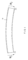
- Fig. 1 is an illustration of principle, in which the roll mantle 11 is bent by means of torques M 1 ,M 2 applied to both ends of the roll mantle 11.
- the magnitude of the torque M 1 can be different from the magnitude of the torque M 2 , in which connection the running of the web proceeding on the roll mantle 11 can be controlled in the axial direction of the roll.
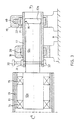
- Fig. 2 shows an embodiment of the arrangement in accordance with the invention.
- the roll of the arrangement consists ot a continuous tubular roll mantle 11 of a composite material, which mantle has been fitted to revolve on the axle journals 12.
- the first support sleeves 13 have been fitted, on which sleeves the roll mantle 11 itself has again been mounted.
- the roll mantle 11 has been mounted on the axle journals 12 by the intermediate of said first support sleeves 13 by means of bearings 14,15.
- the bearings 14,15 have been installed at a distance from one another in the axial X-X direction of the roll, and, thus, the bearings form a pair of bearings.
- the axle journals 12 consist of three parts 12a, 12b, 12c, all of which have different diameters.
- the inner part 12a which extends into the interior of the end area of the roll mantle 11, has the largest diameter D 1
- the following middle part 12b which is directed outwards from the end of the roll mantle 11, has a slightly smaller diameter D 2
- the outer part 12c which follows after the middle part 12b, has again a somewhat smaller diameter D 3 than the middle part 12b.
- the axle journals 12 can, of course, be physically composed of the same piece, in which case said parts 12a, 12b, 12c have been formed, for example, by turning on a lathe.
- a projection 16 which extends around the circumference of the axle journal and which forms an articulation member.
- a second support sleeve 17 Onto the outer part 12c of the axle journal and partly onto the middle part 12b, a second support sleeve 17 has been fitted. This second support sleeve 17 extends beyond the projection 16 provided on the middle part 12b of the axle journal 12, and the inner diameter of the second support sleeve 17 is substantially equal to the outer diameter of the projection 16.
- the second support sleeve 17 has been fixed to the frame R of the machine by means of two fastening members 18, 19.
- the first fastening member 18 is placed at the projection 16, and the second fastening member 19 is placed at a distance from the outer end of the outer part 12c of the axle journal 12 and of the second support sleeve 17.
- bending of the roll into curve form takes place by means of a bending mechanism acting upon the outer end of the outer part 12c of the axle journal 12.
- the bending mechanism consists of a screw member 30 extending through the end of the second support sleeve 17 and through the outer end of the outer part 12c of the axle journal 12.
- the screw member 30 is provided with an outer thread extending substantially through the second support sleeve 17, and the bore which extends through the outer part 12c of the axle journal 12 and which receives the screw member 30 is provided with a corresponding inner thread.
- the second support sleeve 17 can be rotated in the direction of its circumference.
- the screw member 30 and so also the axle journal 12 are rotated correspondingly.
- the desired curve form is regulated for the roll mantle 11
- the direction of the curve form of the roll mantle 11 is regulated in the direction of the circumference of the roll mantle 11.
- the second support sleeve 17 has been mounted in the first 18 and the second 19 fastening member so that it cannot be rotated in relation to the fastening members 18,19 in any other way except by the effect of the regulation device 40.
- the first fastening member 18 is provided with a first bearing member 20, which permits rotation and a slight axial movement of the second support sleeve 17.
- the second fastening member 19 is provided with a corresponding second bearing member 21, which permits a slight axial movement of the second support sleeve 17.
- This second bearing member 21 is locked with the support sleeve 17 so that the support sleeve 17 cannot be rotated in relation to the second bearing member 21 in the direction of the circumference.
- the second bearing member 21 is coupled by means of an intermediate member 22 with the regulation device 40.
- the regulation device 40 acts upon the second support sleeve 17, in which connection the second support sleeve 17 revolves in the direction of the circumference by the effect of the regulation device 40.
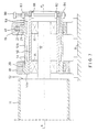
- Fig. 3 shows an embodiment in which the screw member 30 that bends the roll mantle into a curve form is placed between the first fastening member 18 and the end of the roll mantle 11, and not after the second fastening member 19 as is shown in the embodiment of Fig. 2.
- the parts 12b and 12c of the axle journal 12 change positions here, and the articulation member 16 is placed at the second fastening member 19.
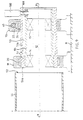
- Fig. 4 shows an embodiment which differs from the embodiment of Fig. 2 in respect of the fastening members 18,19.
- two fully separate fastening members 18,19 have been used, by whose means the second support sleeve 17 fitted on the axle journals 12 has been attached to the frame R of the machine.
- a fastening flange construction is used in which there are two fastening members 18,19, which have a common lower part 90, which is attached to the frame R of the machine.
- the second support sleeve 17 is still attached to the flange construction by means of two fastening points, which flange construction is also possible to think that the lower portion of the fastening flange construction is made of one piece.
- Fig. 5 shows an embodiment which differs from the embodiment shown in Fig. 2 in respect of the roll bending mechanism.
- the roll bending mechanism comprises a screw member 60 parallel to the axis X-X of the roll, provided with an outer thread, and placed at the outer end of the second support sleeve 17.
- the screw member 60 has been fitted in a fitting member 61, which is fixed to the inner face of the second support sleeve 17 at its outer end and which is provided with a bore with an inside thread that receives the screw member 60 and that is parallel to the axis X-X of the roll.
- the inner end of the screw member 60 is placed against the end face of a first wedge member 70.
- the first wedge member 70 moves substantially parallel to the axis X-X of the roll on the inner face of the second support sleeve 17 by the effect of the screw member 60, but it has been locked against the inner face of the second support sleeve 17 to prevent radial movement.
- the wedge face of this first wedge member 70 is again placed against the wedge face of the wedge member 71 attached to the outer part 12c of one of the axle journals 12.
- Fig. 6 shows an embodiment which differs from the embodiments shown in Figs. 2 to 5 in respect of the bending mechanism.
- a hydraulic or pneumatic cylinder or a stepping motor is used as the bending mechanism 100.
- the rod 101 of the cylinder or of the stepping motor has been attached to an extension 12d provided on the axle journal 12, and the cylinder or the motor has been attached to the second support sleeve 17.
- vertical movement of the rod 101 produces bending of the axle journal 12.
- Fig. 7 is a schematic illustration of an embodiment of the arrangement in accordance with the invention, in which embodiment it is a difference as compared with the embodiments shown in Figs. 2 to 6 that the bearings of rotation of the roll are now placed outside the roll mantle 11.
- the axle journal 12 has been attached to the end member 52 of the roll, which end member is fixed to the roll mantle 11, in which case the axle journal 12 revolves along with the roll mantle 11.
- the axle journal 12 has been mounted revolving on a first support sleeve 50 by means of bearings 14,15.
- the axle journal 12 is of substantially uniform thickness at least in respect of its portion between said bearings 14,15.
- the first support sleeve 50 is surrounded by a second support sleeve 51, which has been attached to the frame R of the machine by means of fastening members 18,19, which are placed at said bearings 14,15 in the direction of the axis X-X of the roll.
- a thicker portion 51a which extends across the first fastening member 18 in the direction of the axis X-X of the roll.
- the inner diameter of the second support sleeve 51 is smaller than the inner diameter of the extension part 51b following after the thicker portion 51a.
- an empty space 53 remains, in which the outer end of the first support sleeve 50 can move in the radial direction.
- the thicker portion 51a of the second support sleeve 51 forms an articulation member of the first support sleeve 50, on whose support a little movement between the first support sleeve 50 and the second support sleeve 51 in the direction of the axis X-X of the roll is possible.
- the bending mechanism also comprises a screw member 80 installed outside the second fastening member 19, which screw member extends both through the first support sleeve 50 and through the second support sleeve 51.
- the screw member 80 does not extend through the axle journal 12, which terminates at the second support bearing 15 before the screw member 80.
- the screw member 80 is provided with an outer threading substantially in the portions that pass through the first 50 and the second 51 support sleeves. Movement of the screw member 80 in the direction of its own longitudinal axis in relation to the first support sleeve 50 is prevented by means of locking members 81,82 resting against the inner face of the first support sleeve 50 and attached to the screw member 80, for example, by means of cotter pins. Further, to the outer face of the second support sleeve 51, engagement members 83, 84 have been attached, which are provided with bores with inside thread that receive the screw member 80.
- bending of the axle journal 12 of the roll is produced so that the outer end of the first support sleeve 50 is displaced by means of the screw member 80 in relation to the second support sleeve 51.
- the centre point of the second outer bearing 15 is displaced in relation to the central axis X-X of the roll, in which case the axle journal 12 is bent, and the roll mantle 11 is also bent.
- Fig. 8 shows an embodiment which differs from the embodiment shown in Fig. 7 in respect of the roll bending mechanism.
- a bending mechanism as described in the embodiment shown in Fig. 5 is used.
- the screw member 60 has been fitted in a fitting member 61, which has been attached to the inner face of the second support sleeve 51 at its outer end and which is provided with an inside thread that receives the screw member 60.
- the first support sleeve 50 is slightly shorter than the second support sleeve 51.
- the second wedge member 71 has been attached to the outer face of the first support sleeve 50, in which case, being controlled by the screw member 60, the wedge members 70,71 bend the first support sleeve 50.
- Fig. 9 shows an embodiment which differs from the embodiments shown in Figs. 7 and 8 in respect of the roll bending mechanism.
- a hydraulic or pneumatic cylinder or a stepping motor is used as the bending mechanism 100.
- the rod 101 of the cylinder or stepping motor has been attached to the first support sleeve, and the cylinder or stepping motor has been attached to the second support sleeve.
- vertical movement of the rod 101 produces bending of the axle journal 12.
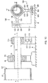
- Fig. 10 shows an embodiment of the present invention, in which the bending takes place by means of two regulation mechanism 120,130 in two planes perpendicular to one another.
- the regulation mechanism 120,130 have been attached from one end to a substantially L-section support beam forming the second fastening member 110, which has again been attached to the frame R of, the machine.
- the opposite ends of the regulation mechanism 120,130 have been attached to a flange 113 that surrounds the second bearing 15.
- the first regulation mechanism 120 displaces the axle journal 12 in the vertical Y-plane
- the second regulation mechanism 130 displaces the axle journal 12 in the horizontal Z-plane.
- the regulation mechanism 120,130 shown in Fig. 10 consist of a nut member 123,133 provided with an inside thread, a first pin 121,131, which is fixed to the flange 113 and which is provided with an outside thread, being fitted to one end of said nut member, an a second pin 122,132, which is fixed to a sledge 124,134 moving on the fastening member 110 and which is provided with an outside thread, being fitted to the opposite end of said nut member 123,133.
- the axle journal 12 and, thereby, the roll mantle 11 can be bent in the Z-plane and/or the Y-plane.
- the sledge 124 which is fitted on the horizontal part of the fastening member 110, can move in the X-plane on support of the wheels 125, but it has been locked in respect of the fastening member 110 against movement in the Y-plane.
- the sledge 134 fitted on the vertical part of the fastening member 110 can move, in the Y-plane on support of the wheels 135, but it has been locked in respect of the fastening member 110 against movement taking place in the X-plane.
- the wheels 125, 135 of the sledges 124,134 revolve on guide rails or equivalent that have been formed on the fastening member 110.
- the wheels 125,135 are just one example of a mode in which the mounting of the sledges 124,134 on the fastening member 110 can be accomplished so that movement of the sledge 124 in the horizontal direction and movement of the sledge 134 in the vertical direction are permitted.
- a nut-pin solution herein it is also possible to employ, for example, a hydraulic or pneumatic cylinder or a stepping motor.
- Fig. 11 shows a variation of the embodiment shown in Fig. 10, in which the journalling and bending of the axle journal 12 are carried out by means of at least one magnetic bearing.
- At least one of the bearings 14,15 is a magnetic bearing 15, by whose means the axle journal 12 of the roll and, thereby, the roll mantle 11 can be bent.
- the axle journal 12 can be displaced eccentrically in relation to the housing.
- the magnetic bearing 15 permits bending of the roll axle 12 and, thus, also of the roll mantle 11 to the desired curve form in the Z-plane and the Y-plane and regulating of the angular position of the arc of the roll mantle 11 formed by bending to the desired position.
- both bearings 14.15 can also be magnetic bearings.
- Fig. 12 shows a second variation of the embodiment shown in Fig. 10, in which the bending of the axle journal 12 and the angular position of the bending are regulated by means of a magnet 260.
- the magnet 260 consists of a number of sector-shaped parts, and the magnetic flux of each sector can be regulated separately.
- Fig. 13 shows a third variation of the embodiment shown in Fig. 10, in which the bending of the axle journal 12 is carried out by means of a nut member 153, and the angular position of the bending is regulated by means or a gear wheel device 150 and a rack device 160.
- the flange 113 which surrounds the second bearing 15 has been attached to the gearwheel device 150 by means of the nut member 153.
- the nut member 153 provided with an inside thread, is similar to the nut members 123,133 shown in Fig. 11, and to one of its ends a pin 151 projecting from the flange 113 and provided with an outside thread has been fitted, and to its opposite end a pin 152 projecting from the gearwheel device 150 and provided with an outside thread has been fitted.
- the gearwheel device 150 comprises a gearwheel 154 mounted on the gearwheel device 150 by means of its shaft 155.
- the shaft 155 of the gearwheel 154 projects from the gearwheel device 150, and the projecting portion is preferably of quadrangular section, in which case it can be rotated, for example, by means of a lever tool suitable for the purpose.
- the rack device 160 comprises a rack 161 substantially shaped as an arc of a circle, along which the gearwheel 154 runs.
- the rack device 160 further comprises a guide part 162, which glides in the guide groove 156 of the gearwheel device 150.
- the rack device 160 is attached to a beam constituting the second fastening member 140, which is again attached to the frame R of the machine.
- the gearwheel 154 of the gearwheel device 150 it is possible to regulate the angular position of the curve form of the roll mantle 11.
- the gearwheel device 150 can be locked in the desired angular position on the rack 161 by means of a screw locking device 157, which tightens the gear wheel device 150 against the rack 161.
- Fig. 14 shows an embodiment which differs from the embodiments shown in the preceding figures in respect of the bending mechanism, the bearing arrangement, and the axle journal.
- the axle journal 12 is of substantially uniform thickness over its entire length, and it is not bent.
- the journalling of the axle journal 12 in a first support sleeve 13 fitted inside the roll mantle 11 has been arranged by means of hydrostatic or hydrodynamic glide bearings 75,76, on whose support the roll mantle 11 revolves in relation to the axle journals 12.
- the glide bearings 75,76 are placed at a distance from one another in the direction of the axis X-X of the roll.
- a duct 72 parallel to the axis X-X of the axle journal has been made into the axle journal 12, together with radial ducts 73,74 at the locations of the glide bearings.
- the first bearing 76 which operates exclusively as a glide bearing, has been attached to the axle journal 12 by means of an articulated joint so that its central axis y-y can turn in relation to the radius of the axle journal 12.
- the second bearing 75 has been provided with a possibility to displace the bearing in the direction of the radius of the axle journal 12.
- This second bearing 75 has been attached to the axle journal 12 so that it can move in the direction of the radius of the axle journal 12, and at the same time its central axis y-y can turn in relation to the radius of the axle journal 12.
- two separately controllable hydraulic feeds 74a,74b are passed into this second bearing 75.
- Figs. 10 to 13 it is shown that the bending is carried out at the second, outer supporting point, in relation to the end member 52 of the roll, but a reversed situation is also possible.
- the bending mechanism is placed at the inner supporting point, and the outer supporting point is fixed.
- the bending of the roll mantle 11 takes place by means of forced shifting by means of a screw member 30,80, a screw-nut assembly 120,130,151 to 153, a wedge member 70, or equivalent.
- the screw member 30, 80, the screw-nut assembly 120,130,151 to 153, the wedge member 70, or equivalent binds the axle journal 12 with the supporting point rigidly, in which case the roll is, so to say, rigidly supported in the sense of vibration.
- the bending of the roll mantle 11 takes place by means of hydraulics, pneumatics, or by means of a stepping motor in which case the roll is, so to say, freely supported or articulation-supported in the sense of vibration.
- a hydraulic medium and a pneumatic medium usually yield to some extent, in which case the support is provided with a slight extent of resilience.
- the bending of the roll mantle 11 takes place directly from the axle journal 12 from inside the supporting points of the axle journal 12.
- the bearings 75,76 bind the roll with the first support sleeve 13 rigidly.
- the roll is rigidly supported in the sense of vibration.
- the lowest natural frequency of the roll becomes more than twice as high as compared with a freely supported roll.
- the natural frequency of a roll becomes higher, it is possible to use smaller roll diameters, in which case the forces transferred from the bending to the frame of the machine are reduced and the cost of manufacture of the roll becomes lower.
Landscapes
- Engineering & Computer Science (AREA)
- General Engineering & Computer Science (AREA)
- Mechanical Engineering (AREA)
- Rolls And Other Rotary Bodies (AREA)
- Paper (AREA)
- Registering, Tensioning, Guiding Webs, And Rollers Therefor (AREA)
- Bending Of Plates, Rods, And Pipes (AREA)
- Professional, Industrial, Or Sporting Protective Garments (AREA)
- Orthopedics, Nursing, And Contraception (AREA)
- Laminated Bodies (AREA)
- Physical Or Chemical Processes And Apparatus (AREA)
- Organic Low-Molecular-Weight Compounds And Preparation Thereof (AREA)
Claims (23)
- Agencement comprenant un cylindre pliable pour matière de type bande, un châssis de machine (R), une construction à bride de fixation (18, 19 ; 18, 110 ; 18, 140) et un mécanisme de pliage (30 ; 60, 70, 71 ; 75 ; 80 ; 100 ; 120, 130 ; 15, 250 ; 15,260; 151 à 153),
dans lequel le cylindre comprend une chemise de cylindre tubulaire continue (11) d'un matériau composite ainsi que des fusées d'essieu (12) connectées à chaque extrémité de la chemise de cylindre (11),
dans lequel la construction à bride de fixation (18, 19 ; 18, 110 ; 18, 140) est fixée au châssis de machine (R),
dans lequel chaque fusée d'essieu (12) est supportée par la construction à bride de fixation (18, 19 ; 18, 110 ; 18, 140), et
dans lequel le mécanisme de pliage (30 ; 60, 70, 71 ; 75 ; 80 ; 100 ; 120, 130 ; 15, 250 ; 15, 260 ; 151 à 153) est prévu pour plier la chemise de cylindre (11) en forme d'arc,
caractérisé en ce que
la construction à bride de fixation (18, 19 ; 18, 110 ; 18, 140) comprend pour chaque fusée d'essieu (12) au moins deux éléments de fixation placés à une certaine distance l'un de l'autre dans la direction de l'axe (X-X) du cylindre, de sorte que chaque fusée d'essieu (12) est supportée au moyen des au moins deux éléments de fixation à au moins deux points de support,
dans lequel un premier élément de fixation (18) des éléments de fixation est situé plus près de l'extrémité de la chemise de cylindre (11) qu'un second élément de fixation (19 ; 110 ; 140) des éléments de fixation, et
en ce que le mécanisme de pliage (30 ; 60, 70, 71 ; 75 ; 80 ; 100 ; 120, 130 ; 15, 250 ; 15, 260 ; 151 à 153) est compris dans la fixation entre les fusées d'essieu (12) et la construction à bride de fixation (18, 19 ; 18, 110 ; 18, 140) ou dans la fixation entre les fusées d'essieu (12) et la chemise de cylindre (11). - Agencement selon la revendication 1, caractérisé en ce que le mécanisme de pliage (30 ; 60, 70, 71 ; 75 ; 80 ; 100 ; 120, 130 ; 15, 250 ; 15, 260 ; 151 à 153) est compris dans la fixation entre les fusées d'essieu (12) et la construction à bride de fixation (18, 19 ; 18, 110 ; 18, 140).
- Agencement selon la revendication 2, caractérisé en ce que la chemise de cylindre (11) est, à chacune de ses extrémités, connectée de façon rotative à la fusée d'essieu (12) située à l'extrémité respective de la chemise de cylindre (11) au moyen de deux paliers (14, 15) placés à une certaine distance l'un de l'autre dans la direction de l'axe (X-X) du cylindre, dans lequel les bagues extérieures desdits paliers (14, 15) sont supportées sur un premier manchon de support (13) placé à l'intérieur d'une pièce d'extrémité de la chemise de cylindre (11), et les bagues intérieures desdits paliers (14, 15) sont supportées sur la fusée d'essieu (12), et en ce que la fusée d'essieu (12) repose au moyen d'un élément d'articulation (16) prévu sur sa face extérieure contre la face intérieure d'un second manchon de support (17) placé dans la construction à bride de fixation (18, 19), la fusée d'essieu (12) étant ainsi supportée à l'un de ses deux points de support.
- Agencement selon la revendication 3, caractérisé en ce que l'élément d'articulation (16) de la fusée d'essieu (12) est placé sensiblement à l'emplacement du premier élément de fixation (18), et en ce que le mécanisme de pliage (30 ; 60, 70, 71 ; 100) est placé sensiblement au niveau ou à proximité du second élément de fixation (19) et supporte la fusée d'essieu (12) à l'autre de ses deux points de support.
- Agencement selon la revendication 3, caractérisé en ce que l'élément d'articulation (16) de la fusée d'essieu (12) est placé sensiblement à l'emplacement du second élément de fixation (19), et en ce que le mécanisme de pliage (30 ; 60, 70, 71 ; 100) est placé sensiblement au niveau ou à proximité du premier élément de fixation (18) et supporte la fusée d'essieu (12) à l'autre de ses deux points de support.
- Agencement selon la revendication 4 ou 5, caractérisé en ce que le mécanisme de pliage comprend un élément à vis (30), qui passe à travers le second manchon de support (17) et à travers la fusée d'essieu (12) et qui est verrouillé contre un mouvement dans la direction de son axe longitudinal au moyen d'éléments de verrouillage (31, 32) supportés contre la face extérieure du second manchon de support (17) et fixé à l'élément à vis (30), dans lequel l'élément à vis (30) est pourvu d'un filet externe sensiblement sur la position qui s'étend à travers le second manchon de support (17), et en ce que le filet externe vient en prise avec un filet interne d'un alésage formé à travers la fusée d'essieu (12), dans lequel, au moyen de l'élément à vis (30), un couple peut être produit et plie la fusée d'essieu (12), lequel couple plie à nouveau la chemise de cylindre (11).
- Agencement selon la revendication 4 ou 5, caractérisé en ce que le mécanisme de pliage (60, 70, 71) comprend un élément à vis (60), qui est pourvu d'un filet externe et qui est placé dans un alésage d'un élément de fixation (61) fixé à la face intérieure du second manchon de support (17), dans lequel l'alésage de l'élément de fixation (61) s'étend en parallèle à l'axe (X-X) du cylindre et est pourvu d'un filet interne venant en prise avec le filet externe de l'élément à vis (60), dans lequel une extrémité de l'élément à vis (60) est placée contre une face d'extrémité d'un premier élément de cale (70), lequel premier élément de cale (70) est mobile le long de la face intérieure du second manchon de support (17) dans la direction parallèle à l'axe (X-X) du cylindre et verrouillé contre la face intérieure du second manchon de support (17) pour empêcher un mouvement radial, et dans lequel le premier élément de cale (70) est, au moyen de sa face de cale, supporté contre la face de cale d'un second élément de cale (71) fixé à la fusée d'essieu (12), de sorte qu'en poussant le premier élément de cale (70) sur le second élément de cale (71) au moyen de l'élément à vis (60), une force peut être produite et plie la fusée d'essieu (12), laquelle force plie à nouveau la chemise de cylindre (11).
- Agencement selon la revendication 4 ou 5, caractérisé en ce que le mécanisme de pliage (100) comprend un vérin hydraulique, un vérin pneumatique ou un moteur pas-à-pas fixé au second manchon de support (17), dans lequel une tige (101) dudit cylindre ou moteur est fixée à la fusée d'essieu (12), de sorte que le mouvement de la tige (101) produit une force qui plie la fusée d'essieu (12), laquelle force plie à nouveau la chemise de cylindre (11).
- Agencement selon la revendication 2, caractérisé en ce que la chemise de cylindre (11) est, à chacune de ses extrémités, directement connectée à la fusée d'essieu (12) située à l'extrémité respective de la chemise de cylindre (11) au moyen d'un élément d'extrémité (52), et en ce que la fusée d'essieu (12) est montée de façon rotative dans un premier manchon de support (50) au moyen de deux paliers (14, 15) placés sensiblement aux emplacements des premier et second éléments de fixation (18, 19), dans lequel ledit premier manchon de support (50) est entouré par un second manchon de support (51), qui est supporté sur les éléments de fixation (18, 19) et qui est pourvu d'une partie plus épaisse (51a) placée à l'emplacement du premier élément de fixation (18), dans lequel la partie plus épaisse (51a) est dirigée vers la fusée d'essieu (12) et forme un élément d'articulation pour le premier manchon de support (50), et dans lequel le premier manchon de support (50) et le second manchon de support (51) s'étendent, dans la direction de l'axe (X-X) du cylindre, au-delà de l'emplacement du second élément de fixation (19).
- Agencement selon la revendication 9, caractérisé en ce que le mécanisme de pliage comprend un élément à vis (80), qui passe à travers le premier manchon de support (50) et le second manchon de support (51) au niveau de leurs parties s'étendant au-delà du second élément de fixation (19), dans lequel le mouvement dudit élément à vis (80) dans la direction de son axe longitudinal en relation avec le premier manchon de support (50) est empêché au moyen d'éléments de verrouillage (81, 82) fixés à l'élément à vis (80) et supportés contre la face intérieure du premier manchon de support (50), et dans lequel ledit élément à vis (80) est connecté à des éléments de mise en prise (83, 84) fixés à la face extérieure du second manchon de support (51) et pourvu d'alésages avec un filet interne qui viennent en prise avec un filet externe sur l'élément à vis (80), dans lequel, au moyen de l'élément à vis (80), un couple peut être produit et plie le premier manchon de support (50) et ainsi la fusée d'essieu (12), et lequel couple plie également la chemise de cylindre (11).
- Agencement selon la revendication 9, caractérisé en ce que le mécanisme de pliage (60, 70, 71) comprend un élément à vis (60), qui est pourvu d'un filet externe et qui est placé dans un alésage d'un élément de fixation (61) fixé à la face intérieure du second manchon de support (51), dans lequel l'alésage de l'élément de fixation (61) s'étend en parallèle à l'axe (X-X) du cylindre et est pourvu d'un filet interne venant en prise avec le filet externe de l'élément à vis (60), dans lequel une extrémité de l'élément à vis (60) est placée contre une face d'extrémité d'un premier élément de cale (70), lequel premier élément de cale (70) est mobile le long de la face intérieure du second manchon de support (51) dans la direction parallèle à l'axe (X-X) du cylindre et est verrouillé contre la face intérieure du second manchon de support (51) pour empêcher un mouvement radial, et dans lequel le premier élément de cale (70) est, au moyen de sa face de cale, supporté contre la face de cale d'un second élément de cale (71) fixé à la face extérieure du premier manchon de support (50), de sorte qu'en poussant le premier élément de cale (70) sur le second élément de cale (71) au moyen de l'élément à vis (60), un couple peut être produit et plie le premier manchon de support (50) et ainsi la fusée d'essieu (12), lequel couple plie à nouveau la chemise de cylindre (11).
- Agencement selon la revendication 9, caractérisé en ce que le mécanisme de pliage comprend un vérin hydraulique, un vérin pneumatique ou un moteur pas-à-pas (100) fixé au second manchon de support (51), dans lequel une tige (101) dudit cylindre ou moteur est fixée au premier manchon de support (50) au niveau de sa partie s'étendant au-delà du second élément de fixation (19), de sorte que, en déplaçant la tige (101), un couple peut être produit et plie le premier manchon de support (50) et ainsi la fusée d'essieu (12), et lequel couple plie également la chemise de cylindre (11).
- Agencement selon l'une des revendications 3 à 12, caractérisé en ce que, sur le second élément de fixation (19), un dispositif de régulation (40) est placé et agit sur un élément de palier (21) supporté contre la face extérieure du second manchon de support (17, 51) par l'intermédiaire d'un élément intermédiaire (22), de sorte qu'un mouvement rotatif du dispositif de régulation (40) dans la direction de la circonférence du cylindre produit un mouvement rotatif correspondant du second manchon de support (17, 51) et à partir de lui, par l'intermédiaire du mécanisme de pliage (30 ; 60, 70, 71 ; 80 ; 100), de la fusée d'essieu (12) afin de contrôler la direction radiale de l'arc de pliage de la chemise de cylindre (11).
- Agencement selon la revendication 2, caractérisé en ce que la chemise de cylindre (11) est, à chacune de ses extrémités, directement connectée à la fusée d'essieu (12) au moyen d'un élément d'extrémité (52), et en ce que la fusée d'essieu (12) est montée de façon rotative au moyen d'un premier palier (14) fixé au premier élément de fixation (18) et au moyen d'un second palier (15) fixé au second élément de fixation (19 ; 110 ; 140).
- Agencement selon la revendication 14, caractérisé en ce que le mécanisme de pliage (120, 130) comprend un premier mécanisme de régulation (120) placé entre le second élément de fixation (110) et une bride (113) entourant le second palier (15), le premier mécanisme de régulation (120) agissant sur un plan sensiblement vertical incluant l'axe (X-X) du cylindre, et un second mécanisme de régulation (130) placé entre le second élément de fixation (110) et la bride (113), le second mécanisme de régulation (130) agissant sur un plan sensiblement horizontal incluant l'axe (X-X) du cylindre.
- Agencement selon la revendication 15, caractérisé en ce que le premier mécanisme de régulation (120) et le second mécanisme de régulation (130) comprennent chacun une première broche (121, 131) fixée à la bride (113) et pourvue d'un filet externe, et une seconde broche opposée (122, 132) fixée à une masse (124, 134) mobile sur le second élément de fixation (110) et pourvue d'un filet externe, dans lequel les broches opposées (121, 122 ; 131, 132) sont interconnectées au moyen d'un élément d'écrou (123, 133) pourvu d'un filet interne, dans lequel en tournant l'élément d'écrou (123, 133) la forme d'arc de la chemise de cylindre (11) et la position angulaire de la forme d'arc de la chemise de cylindre (11) peuvent être régulées.
- Agencement selon la revendication 14, caractérisé en ce que au moins le second palier (15) est un palier comprenant des aimants (250), au moyen desquels la forme d'arc de la chemise de cylindre (11) et la position angulaire de la forme d'arc de la chemise de cylindre (11) peuvent être régulées.
- Agencement selon la revendication 14, caractérisé en ce qu'une bride (19a) qui entoure le second palier (15) et une partie de base (19b) du second élément de fixation (19), qui est fixé au châssis de machine (R), communiquent l'une avec l'autre au moyen d'un aimant (260), au moyen desquels la forme d'arc de la chemise de cylindre (11) et la position angulaire de la forme d'arc de la chemise de cylindre (11) peuvent être régulées.
- Agencement selon la revendication 14, caractérisé en ce que, à une bride de fixation (113) du second palier (15), une première broche (151) pourvue d'un filet externe est fixée, en ce qu'un dispositif à roue dentée (150) mobile sur le second élément de fixation (140), une seconde broche opposée (152) pourvue d'un filet externe est fixée, lesquelles broches opposées (151, 152) sont interconnectées au moyen d'un élément d'écrou (153) pourvu d'un filet interne, et en ce qu'une roue dentée (154) du dispositif à roue dentée (150) vient en prise avec une crémaillère (161), façonnée comme un arc de cercle, du dispositif de crémaillère (160) fixé au second élément de fixation (140) et est mobile le long de la crémaillère (161), de sorte que la forme d'arc de la chemise de cylindre (11) peut être régulée en tournant l'élément d'écrou (153) et de sorte que la position angulaire de la forme d'arc de la chemise de cylindre (11) peut être régulée en déplaçant le dispositif à roue dentée (150) le long de la crémaillère (161).
- Agencement selon la revendication 1, caractérisé en ce que le mécanisme de pliage (75) est compris dans la fixation entre les fusées d'essieu (12) et la chemise de cylindre (11).
- Agencement selon la revendication 20, caractérisé en ce que la chemise de cylindre (11) est, à chacune de ses extrémités, connectée de façon rotative à la fusée d'essieu (12) située à l'extrémité respective de la chemise de cylindre (11) au moyen de deux paliers coulissants hydrostatiques ou hydrodynamiques (75, 76) agissant sur un manchon de support (13) placé à l'intérieur d'une partie d'extrémité de la chemise de cylindre (11) et supportés contre la fusée d'essieu (12), lesquels paliers coulissants (75, 76) sont fixés à la fusée d'essieu (12) de sorte que leur axe central (Y-Y) peut tourner par rapport à la direction radiale de la fusée d'essieu (12), et lesquels paliers coulissants (75, 76) sont fixés à la fusée d'essieu (12) à une distance l'un de l'autre dans la direction de l'axe (X-X) du cylindre.
- Agencement selon la revendication 21, caractérisé en ce que, dans l'un des paliers coulissants (75), un milieu hydraulique est fourni au moyen de deux alimentations séparément contrôlables (74a, 74b), dans lequel le palier coulissant (75) peut être déplacé dans la direction du rayon de l'axe (X-X) du cylindre de sorte que l'axe central (Y-Y) du palier coulissant (75) forme un angle en rapport avec la direction radiale de l'axe (X-X) du cylindre, en conséquence duquel la chemise de cylindre (11) est pliée.
- Agencement selon la revendication 22, caractérisé en ce que le second élément de fixation (19) est pourvu d'un dispositif de régulation (40), qui agit sur un élément de palier (21) supporté contre la face extérieure de la fusée d'essieu (12) par l'intermédiaire d'un élément intermédiaire (22), de sorte qu'un mouvement rotatif du dispositif de régulation (40) dans la direction de la circonférence du cylindre produit un mouvement rotatif correspondant de la fusée d'essieu (12) afin de contrôler la direction radiale de l'arc de pliage de la chemise de cylindre (11).
Applications Claiming Priority (5)
| Application Number | Priority Date | Filing Date | Title |
|---|---|---|---|
| FI973388A FI102560B1 (fi) | 1997-08-19 | 1997-08-19 | Taivutettava tela rainamaista materiaalia varten |
| FI973388 | 1997-08-19 | ||
| FI980071 | 1998-01-15 | ||
| FI980071A FI103071B (fi) | 1997-08-19 | 1998-01-15 | Taivutettava tela rainamaista materiaalia varten |
| PCT/FI1998/000623 WO1999009329A1 (fr) | 1997-08-19 | 1998-08-11 | Cylindre pour matiere de type bande pouvant etre cintre |
Publications (2)
| Publication Number | Publication Date |
|---|---|
| EP1003980A1 EP1003980A1 (fr) | 2000-05-31 |
| EP1003980B1 true EP1003980B1 (fr) | 2007-10-03 |
Family
ID=26160427
Family Applications (1)
| Application Number | Title | Priority Date | Filing Date |
|---|---|---|---|
| EP98938719A Expired - Lifetime EP1003980B1 (fr) | 1997-08-19 | 1998-08-11 | Cylindre pour matiere de type bande pouvant etre cintre |
Country Status (9)
| Country | Link |
|---|---|
| US (1) | US6524227B1 (fr) |
| EP (1) | EP1003980B1 (fr) |
| JP (1) | JP4077153B2 (fr) |
| AT (1) | ATE374889T1 (fr) |
| AU (1) | AU8733698A (fr) |
| CA (1) | CA2301276C (fr) |
| DE (1) | DE69838504T2 (fr) |
| FI (1) | FI103071B (fr) |
| WO (1) | WO1999009329A1 (fr) |
Families Citing this family (19)
| Publication number | Priority date | Publication date | Assignee | Title |
|---|---|---|---|---|
| FI105116B (fi) | 1998-11-30 | 2000-06-15 | Valmet Corp Valmet Corp | Paperi- tai kartonkikoneessa käytettävä taivutettava palkki |
| FI106741B (fi) | 2000-03-16 | 2001-03-30 | Metso Paper Inc | Komposiittivaippainen taivutettava tela |
| DE20006302U1 (de) * | 2000-04-06 | 2001-10-25 | Band-Zink-GmbH, 40764 Langenfeld | Beschichtungsvorrichtung |
| DE20309301U1 (de) * | 2003-06-13 | 2003-08-28 | Stowe Woodward AG, 33758 Schloß Holte-Stukenbrock | Breitstreckwalze |
| DE10335758C5 (de) * | 2003-08-05 | 2015-12-03 | Manroland Web Systems Gmbh | Verfahren und Druckwerk zur Beeinflussung der lateralen Bahnspreizung insbesondere an Rotationsdruckmaschinen |
| DE10340569A1 (de) * | 2003-09-01 | 2005-04-07 | Koenig & Bauer Ag | Verfahren zur Reduktion von Passerfehlern auf einer in einer bahnverarbeitenden Vorrichtung und ein Druckwerk |
| DE10341119A1 (de) * | 2003-09-05 | 2005-03-31 | Voith Paper Patent Gmbh | Breitstreckwalze |
| DE202004021651U1 (de) | 2004-05-29 | 2009-10-08 | Voith Patent Gmbh | Drehteil |
| FI116745B (fi) * | 2004-07-13 | 2006-02-15 | Pr Rolls Oy | Taivutettava tela |
| FI117640B (fi) * | 2004-07-28 | 2006-12-29 | Metso Paper Inc | Johtotela rainanmuodostuskonetta varten ja menetelmät vastaavan johtotelan valmistamiseksi ja käyttämiseksi |
| FI117646B (fi) | 2004-10-04 | 2006-12-29 | Metso Paper Inc | Tela |
| DE102005044956A1 (de) * | 2005-09-20 | 2007-03-22 | Voith Patent Gmbh | Breitstreckwalze |
| AU2006225177B2 (en) * | 2006-01-12 | 2009-05-21 | Innovative Design Co Pty Ltd | Container closure |
| FR2919511B1 (fr) * | 2007-07-30 | 2010-01-29 | Snecma Propulsion Solide | Rouleau composite thermostructural |
| FI123493B (fi) | 2009-08-04 | 2013-05-31 | Finbow Oy | Kaarevan telan kiinnityselin sekä järjestely ja menetelmä kaarevan telan värähtelyn hallintaan |
| DE102009048074A1 (de) | 2009-10-01 | 2011-04-07 | Brückner Maschinenbau GmbH & Co. KG | Reckwalze sowie zugehöriges Längsreckwerk oder -stufe |
| JP6163805B2 (ja) * | 2013-03-15 | 2017-07-19 | 株式会社リコー | 画像形成装置 |
| KR102773614B1 (ko) * | 2021-11-03 | 2025-02-25 | 주식회사 엘지에너지솔루션 | 자재 지지용 롤러 |
| JP7790793B1 (ja) * | 2025-07-07 | 2025-12-23 | 株式会社小林製作所 | コンタクトロール装置 |
Family Cites Families (38)
| Publication number | Priority date | Publication date | Assignee | Title |
|---|---|---|---|---|
| US1848547A (en) * | 1932-03-08 | b scharnberg | ||
| US2676387A (en) * | 1951-07-11 | 1954-04-27 | Downingtown Mfg Co | Mounting for smoothing press rolls |
| US2771658A (en) * | 1953-08-03 | 1956-11-27 | Hunter James Machine Co | Roll for expanding and contracting textiles |
| US2955897A (en) * | 1956-10-01 | 1960-10-11 | Kidde Textile Machinery Corp | Warping machine |
| US2898662A (en) * | 1957-05-17 | 1959-08-11 | Mount Hope Machinery Ltd | Expanding and contracting rolls |
| US2960749A (en) * | 1958-08-20 | 1960-11-22 | Mount Hope Machinery Ltd | Expanding and contracting rolls |
| US3085503A (en) * | 1960-11-16 | 1963-04-16 | Black Clawson Co | Paper machinery |
| US3168435A (en) * | 1960-11-25 | 1965-02-02 | Beloit Corp | Method and means for mounting, driving and supporting rolls for endless moving bands |
| US3094771A (en) * | 1961-06-13 | 1963-06-25 | Mount Hope Machinery Ltd | Table roll with means for removing longitudinal curvature |
| US3182787A (en) * | 1963-10-15 | 1965-05-11 | Joy Mfg Co | Conveyor device |
| US3347157A (en) * | 1965-04-30 | 1967-10-17 | Farrel Corp | Roll structures and method |
| US3373588A (en) * | 1965-08-17 | 1968-03-19 | United Eng Foundry Co | Crown control for rolling mill |
| US3443295A (en) * | 1966-02-04 | 1969-05-13 | Beloit Corp | Table roll |
| US3438100A (en) * | 1966-05-06 | 1969-04-15 | Beloit Eastern Corp | Adjustable shot roll |
| US3448683A (en) * | 1966-12-16 | 1969-06-10 | Adamson United Co | Calender with removable bearing pressure mechanism |
| US3537665A (en) * | 1968-10-18 | 1970-11-03 | United Eng Foundry Co | Replaceable mandrel for tension reel |
| US3604087A (en) * | 1970-03-13 | 1971-09-14 | Beloit Corp | Antideflection roll |
| AT311167B (de) * | 1970-07-08 | 1973-11-12 | Joseph Eck & Soehne Kg | Knickwalze, insbesondere für Papierkalander |
| DE2042001A1 (de) * | 1970-08-25 | 1972-04-27 | Kleinewefers Ind Co Gmbh | Leitwalze an Kalandern |
| US4011938A (en) * | 1975-09-08 | 1977-03-15 | Kain Arthur F | Suspension idler |
| CH611990A5 (fr) * | 1977-01-17 | 1979-06-29 | Sulzer Ag | |
| US4180296A (en) * | 1978-01-06 | 1979-12-25 | Societe Europeenne De Propulsion | Axial electromagnetic bearing for a shaft rotating at high speed |
| CA1109015A (fr) * | 1979-02-20 | 1981-09-15 | Ronald G. Dunk | Mecanisme d'entrainement et de soutien de rouleaux en ceramique, et mode d'emploi connexe |
| CH648238A5 (de) * | 1979-10-09 | 1985-03-15 | Roland Man Druckmasch | Vorrichtung zum durchbiegen einer druckwalze einer rotationsdruckmaschine. |
| US4364158A (en) * | 1980-09-02 | 1982-12-21 | Usm Corporation | Roll bending apparatus |
| FI67675C (fi) * | 1980-09-04 | 1985-05-10 | Frankenthal Ag Albert | Cylinder foer banformiga material bearbetande maskiner |
| FI811720A7 (fi) * | 1981-06-03 | 1982-12-04 | Waertsilae Oy Ab | Telarakennelma. |
| IT1155103B (it) * | 1982-03-03 | 1987-01-21 | Componenti Grafici Srl | Cilindro di pressione con asse a configurazione variabile |
| DE3826980A1 (de) * | 1987-08-13 | 1989-02-23 | Barmag Barmer Maschf | Fliegend gelagerte streckgalette |
| US5061533A (en) * | 1988-10-11 | 1991-10-29 | Mitsubishi Rayon Company Ltd. | Roll formed of carbon fiber composite material |
| DE3912303C2 (de) * | 1989-04-14 | 1994-08-04 | Troester Maschf Paul | Kalander für die Herstellung von Dichtungsplatten |
| CH680151A5 (fr) * | 1989-11-09 | 1992-06-30 | Escher Wyss Ag | |
| FI87485C (fi) * | 1991-01-07 | 1993-01-11 | Valmet Paper Machinery Inc | Boejningsreglerbar vals |
| JPH08244108A (ja) * | 1995-03-13 | 1996-09-24 | Toshiba Mach Co Ltd | シート等の成形用のロールベンディング装置 |
| DE29508422U1 (de) * | 1995-05-20 | 1995-08-10 | Voith Sulzer Papiermaschinen GmbH, 89522 Heidenheim | Walze mit Schwingungsdämpfer |
| JPH08326755A (ja) * | 1995-06-05 | 1996-12-10 | Hitachi Ltd | 軸受ユニット |
| DE19616802A1 (de) * | 1996-04-26 | 1997-10-30 | Voith Sulzer Papiermasch Gmbh | Durchbiegungsausgleichswalze |
| US5739609A (en) * | 1997-04-09 | 1998-04-14 | Koyo Seiko Co., Ltd. | Magnetic bearing apparatus |
-
1998
- 1998-01-15 FI FI980071A patent/FI103071B/fi not_active IP Right Cessation
- 1998-08-11 WO PCT/FI1998/000623 patent/WO1999009329A1/fr not_active Ceased
- 1998-08-11 EP EP98938719A patent/EP1003980B1/fr not_active Expired - Lifetime
- 1998-08-11 US US09/485,976 patent/US6524227B1/en not_active Expired - Fee Related
- 1998-08-11 CA CA002301276A patent/CA2301276C/fr not_active Expired - Fee Related
- 1998-08-11 DE DE69838504T patent/DE69838504T2/de not_active Expired - Lifetime
- 1998-08-11 AT AT98938719T patent/ATE374889T1/de active
- 1998-08-11 AU AU87336/98A patent/AU8733698A/en not_active Abandoned
- 1998-08-11 JP JP2000509960A patent/JP4077153B2/ja not_active Expired - Fee Related
Non-Patent Citations (1)
| Title |
|---|
| None * |
Also Published As
| Publication number | Publication date |
|---|---|
| US6524227B1 (en) | 2003-02-25 |
| DE69838504T2 (de) | 2008-04-24 |
| FI980071L (fi) | 1999-02-20 |
| CA2301276A1 (fr) | 1999-02-25 |
| FI980071A0 (fi) | 1998-01-15 |
| FI103071B1 (fi) | 1999-04-15 |
| EP1003980A1 (fr) | 2000-05-31 |
| DE69838504D1 (de) | 2007-11-15 |
| JP4077153B2 (ja) | 2008-04-16 |
| AU8733698A (en) | 1999-03-08 |
| FI103071B (fi) | 1999-04-15 |
| JP2001515192A (ja) | 2001-09-18 |
| WO1999009329A1 (fr) | 1999-02-25 |
| ATE374889T1 (de) | 2007-10-15 |
| CA2301276C (fr) | 2007-11-27 |
Similar Documents
| Publication | Publication Date | Title |
|---|---|---|
| US6524227B1 (en) | Roll that can be bent for a web-like material | |
| US7867155B2 (en) | Expander roller | |
| US7824320B2 (en) | Expander roller | |
| CA2177797C (fr) | Agencement d'entrainement pour cylindre d'enduction | |
| US7789818B2 (en) | Rotary part | |
| CA2340870C (fr) | Cylindre pouvant etre replie avec une chemise en composite | |
| WO1980000032A1 (fr) | Appareil de transformation d'un mouvement rotatif en un mouvement lineaire | |
| US4856155A (en) | Method and device in an adjustable-crown roll | |
| US6494823B2 (en) | Take-out roll, spreader roll, or equivalent for a web-like material | |
| CN100504088C (zh) | 辊 | |
| WO1998012381A1 (fr) | Rouleau de guidage d'une bande mobile | |
| US6409643B2 (en) | Take-out leading roll, spreader roll, or equivalent for a web-like material | |
| EP0626336B1 (fr) | Procédé et montage pour ajuster la direction d'une roue pour rail | |
| FI102560B (fi) | Taivutettava tela rainamaista materiaalia varten | |
| EP0786032B1 (fr) | Appareil pour positionner dans le sens axial la virole de cylindre dans un cylindre a deviation controlee charge de maniere hydrostatique | |
| US6521092B2 (en) | Beam that can be bent for use in a paper or board machine | |
| CA2224221C (fr) | Agencement de palier et element d'accouplement d'un rouleau repartiteur | |
| JP3095650B2 (ja) | 軸受メタル可変位相型軸受 | |
| WO1998033732A1 (fr) | Rouleau, en particulier, rouleau prevu pour etre utilise dans un dispositif d'enroulement | |
| KR20260056571A (ko) | 구동측과 종동측을 연동하여 제어하는 벨트형 기어 변속기 | |
| JP2008506914A (ja) | 屈曲可能なシリンダ | |
| EP1771621B1 (fr) | Rouleau de guidage pour une machine de formation de bande et methodes de fabrication et d'utilisation du rouleau de guidage correspondant |
Legal Events
| Date | Code | Title | Description |
|---|---|---|---|
| PUAI | Public reference made under article 153(3) epc to a published international application that has entered the european phase |
Free format text: ORIGINAL CODE: 0009012 |
|
| 17P | Request for examination filed |
Effective date: 20000218 |
|
| AK | Designated contracting states |
Kind code of ref document: A1 Designated state(s): AT DE FR GB IT SE |
|
| RAP1 | Party data changed (applicant data changed or rights of an application transferred) |
Owner name: METSO PAPER, INC. |
|
| 17Q | First examination report despatched |
Effective date: 20031219 |
|
| GRAP | Despatch of communication of intention to grant a patent |
Free format text: ORIGINAL CODE: EPIDOSNIGR1 |
|
| GRAS | Grant fee paid |
Free format text: ORIGINAL CODE: EPIDOSNIGR3 |
|
| GRAA | (expected) grant |
Free format text: ORIGINAL CODE: 0009210 |
|
| AK | Designated contracting states |
Kind code of ref document: B1 Designated state(s): AT DE FR GB IT SE |
|
| REG | Reference to a national code |
Ref country code: GB Ref legal event code: FG4D |
|
| REF | Corresponds to: |
Ref document number: 69838504 Country of ref document: DE Date of ref document: 20071115 Kind code of ref document: P |
|
| PG25 | Lapsed in a contracting state [announced via postgrant information from national office to epo] |
Ref country code: SE Free format text: LAPSE BECAUSE OF FAILURE TO SUBMIT A TRANSLATION OF THE DESCRIPTION OR TO PAY THE FEE WITHIN THE PRESCRIBED TIME-LIMIT Effective date: 20080103 |
|
| ET | Fr: translation filed | ||
| PLBE | No opposition filed within time limit |
Free format text: ORIGINAL CODE: 0009261 |
|
| STAA | Information on the status of an ep patent application or granted ep patent |
Free format text: STATUS: NO OPPOSITION FILED WITHIN TIME LIMIT |
|
| 26N | No opposition filed |
Effective date: 20080704 |
|
| PGFP | Annual fee paid to national office [announced via postgrant information from national office to epo] |
Ref country code: IT Payment date: 20110824 Year of fee payment: 14 |
|
| PGFP | Annual fee paid to national office [announced via postgrant information from national office to epo] |
Ref country code: GB Payment date: 20120821 Year of fee payment: 15 |
|
| PGFP | Annual fee paid to national office [announced via postgrant information from national office to epo] |
Ref country code: FR Payment date: 20120906 Year of fee payment: 15 Ref country code: DE Payment date: 20120822 Year of fee payment: 15 |
|
| PGFP | Annual fee paid to national office [announced via postgrant information from national office to epo] |
Ref country code: AT Payment date: 20120813 Year of fee payment: 15 |
|
| PG25 | Lapsed in a contracting state [announced via postgrant information from national office to epo] |
Ref country code: IT Free format text: LAPSE BECAUSE OF NON-PAYMENT OF DUE FEES Effective date: 20120811 |
|
| REG | Reference to a national code |
Ref country code: AT Ref legal event code: MM01 Ref document number: 374889 Country of ref document: AT Kind code of ref document: T Effective date: 20130811 |
|
| GBPC | Gb: european patent ceased through non-payment of renewal fee |
Effective date: 20130811 |
|
| PG25 | Lapsed in a contracting state [announced via postgrant information from national office to epo] |
Ref country code: DE Free format text: LAPSE BECAUSE OF NON-PAYMENT OF DUE FEES Effective date: 20140301 |
|
| REG | Reference to a national code |
Ref country code: FR Ref legal event code: ST Effective date: 20140430 |
|
| REG | Reference to a national code |
Ref country code: DE Ref legal event code: R119 Ref document number: 69838504 Country of ref document: DE Effective date: 20140301 |
|
| PG25 | Lapsed in a contracting state [announced via postgrant information from national office to epo] |
Ref country code: AT Free format text: LAPSE BECAUSE OF NON-PAYMENT OF DUE FEES Effective date: 20130811 |
|
| PG25 | Lapsed in a contracting state [announced via postgrant information from national office to epo] |
Ref country code: GB Free format text: LAPSE BECAUSE OF NON-PAYMENT OF DUE FEES Effective date: 20130811 |
|
| PG25 | Lapsed in a contracting state [announced via postgrant information from national office to epo] |
Ref country code: FR Free format text: LAPSE BECAUSE OF NON-PAYMENT OF DUE FEES Effective date: 20130902 |