EP1004001B1 - Accumulateur a sorption, dispositif et procede d'accumulation de chaleur - Google Patents
Accumulateur a sorption, dispositif et procede d'accumulation de chaleur Download PDFInfo
- Publication number
- EP1004001B1 EP1004001B1 EP98940226A EP98940226A EP1004001B1 EP 1004001 B1 EP1004001 B1 EP 1004001B1 EP 98940226 A EP98940226 A EP 98940226A EP 98940226 A EP98940226 A EP 98940226A EP 1004001 B1 EP1004001 B1 EP 1004001B1
- Authority
- EP
- European Patent Office
- Prior art keywords
- sorption
- heat
- adsorber
- several
- adsorbate
- Prior art date
- Legal status (The legal status is an assumption and is not a legal conclusion. Google has not performed a legal analysis and makes no representation as to the accuracy of the status listed.)
- Expired - Lifetime
Links
- 238000001179 sorption measurement Methods 0.000 title claims abstract description 183
- 238000000034 method Methods 0.000 title claims description 7
- 239000002156 adsorbate Substances 0.000 claims abstract description 67
- XLYOFNOQVPJJNP-UHFFFAOYSA-N water Substances O XLYOFNOQVPJJNP-UHFFFAOYSA-N 0.000 claims abstract description 53
- 239000000463 material Substances 0.000 claims abstract description 32
- 230000005494 condensation Effects 0.000 claims abstract description 17
- 238000009833 condensation Methods 0.000 claims abstract description 16
- 238000010438 heat treatment Methods 0.000 claims description 32
- 238000009413 insulation Methods 0.000 claims description 13
- QGZKDVFQNNGYKY-UHFFFAOYSA-N Ammonia Chemical compound N QGZKDVFQNNGYKY-UHFFFAOYSA-N 0.000 claims description 10
- VYPSYNLAJGMNEJ-UHFFFAOYSA-N Silicium dioxide Chemical compound O=[Si]=O VYPSYNLAJGMNEJ-UHFFFAOYSA-N 0.000 claims description 9
- 239000000741 silica gel Substances 0.000 claims description 9
- 229910002027 silica gel Inorganic materials 0.000 claims description 9
- OKTJSMMVPCPJKN-UHFFFAOYSA-N Carbon Chemical compound [C] OKTJSMMVPCPJKN-UHFFFAOYSA-N 0.000 claims description 6
- 238000001704 evaporation Methods 0.000 claims description 6
- 230000008020 evaporation Effects 0.000 claims description 6
- 239000003463 adsorbent Substances 0.000 claims description 5
- 229910021529 ammonia Inorganic materials 0.000 claims description 5
- 239000002689 soil Substances 0.000 claims description 5
- 239000002023 wood Substances 0.000 claims description 5
- PNEYBMLMFCGWSK-UHFFFAOYSA-N Alumina Chemical compound [O-2].[O-2].[O-2].[Al+3].[Al+3] PNEYBMLMFCGWSK-UHFFFAOYSA-N 0.000 claims description 4
- 229910000831 Steel Inorganic materials 0.000 claims description 4
- 239000010959 steel Substances 0.000 claims description 4
- 230000000694 effects Effects 0.000 claims description 2
- 230000020169 heat generation Effects 0.000 claims description 2
- 239000000843 powder Substances 0.000 claims description 2
- 235000012206 bottled water Nutrition 0.000 claims 4
- 239000003651 drinking water Substances 0.000 claims 4
- 238000009825 accumulation Methods 0.000 claims 3
- 239000003795 chemical substances by application Substances 0.000 claims 2
- 238000003860 storage Methods 0.000 abstract description 91
- XUIMIQQOPSSXEZ-UHFFFAOYSA-N Silicon Chemical compound [Si] XUIMIQQOPSSXEZ-UHFFFAOYSA-N 0.000 abstract 1
- 229910052710 silicon Inorganic materials 0.000 abstract 1
- 239000010703 silicon Substances 0.000 abstract 1
- 239000006200 vaporizer Substances 0.000 abstract 1
- 230000015654 memory Effects 0.000 description 28
- 238000005192 partition Methods 0.000 description 13
- 239000002594 sorbent Substances 0.000 description 11
- OKKJLVBELUTLKV-UHFFFAOYSA-N Methanol Chemical compound OC OKKJLVBELUTLKV-UHFFFAOYSA-N 0.000 description 9
- 239000007788 liquid Substances 0.000 description 9
- 238000003795 desorption Methods 0.000 description 8
- 238000011068 loading method Methods 0.000 description 8
- 239000012530 fluid Substances 0.000 description 7
- 238000005338 heat storage Methods 0.000 description 6
- 239000003990 capacitor Substances 0.000 description 5
- 238000001816 cooling Methods 0.000 description 5
- 238000009826 distribution Methods 0.000 description 5
- 239000006260 foam Substances 0.000 description 5
- 239000011159 matrix material Substances 0.000 description 5
- 229910052751 metal Inorganic materials 0.000 description 4
- 239000002184 metal Substances 0.000 description 4
- 238000012546 transfer Methods 0.000 description 4
- 150000001298 alcohols Chemical class 0.000 description 3
- 230000005855 radiation Effects 0.000 description 3
- 239000010457 zeolite Substances 0.000 description 3
- 229910021536 Zeolite Inorganic materials 0.000 description 2
- 239000002250 absorbent Substances 0.000 description 2
- 230000002745 absorbent Effects 0.000 description 2
- 239000006096 absorbing agent Substances 0.000 description 2
- 238000002485 combustion reaction Methods 0.000 description 2
- HNPSIPDUKPIQMN-UHFFFAOYSA-N dioxosilane;oxo(oxoalumanyloxy)alumane Chemical compound O=[Si]=O.O=[Al]O[Al]=O HNPSIPDUKPIQMN-UHFFFAOYSA-N 0.000 description 2
- 238000007599 discharging Methods 0.000 description 2
- 239000008187 granular material Substances 0.000 description 2
- 239000010439 graphite Substances 0.000 description 2
- 229910002804 graphite Inorganic materials 0.000 description 2
- 239000011148 porous material Substances 0.000 description 2
- 239000007787 solid Substances 0.000 description 2
- 238000010521 absorption reaction Methods 0.000 description 1
- 230000033228 biological regulation Effects 0.000 description 1
- 238000006243 chemical reaction Methods 0.000 description 1
- 238000013461 design Methods 0.000 description 1
- 238000011161 development Methods 0.000 description 1
- 230000005611 electricity Effects 0.000 description 1
- 238000005516 engineering process Methods 0.000 description 1
- 239000000835 fiber Substances 0.000 description 1
- 238000010304 firing Methods 0.000 description 1
- 238000005187 foaming Methods 0.000 description 1
- 230000006870 function Effects 0.000 description 1
- 239000003365 glass fiber Substances 0.000 description 1
- 239000013529 heat transfer fluid Substances 0.000 description 1
- 238000011031 large-scale manufacturing process Methods 0.000 description 1
- 230000007774 longterm Effects 0.000 description 1
- 238000012423 maintenance Methods 0.000 description 1
- 238000004519 manufacturing process Methods 0.000 description 1
- 239000000203 mixture Substances 0.000 description 1
- 210000000056 organ Anatomy 0.000 description 1
- 238000013021 overheating Methods 0.000 description 1
- TWNQGVIAIRXVLR-UHFFFAOYSA-N oxo(oxoalumanyloxy)alumane Chemical compound O=[Al]O[Al]=O TWNQGVIAIRXVLR-UHFFFAOYSA-N 0.000 description 1
- 239000008188 pellet Substances 0.000 description 1
- 229920000642 polymer Polymers 0.000 description 1
- 238000001556 precipitation Methods 0.000 description 1
- 230000000750 progressive effect Effects 0.000 description 1
- 239000008213 purified water Substances 0.000 description 1
- 239000003507 refrigerant Substances 0.000 description 1
- 230000001105 regulatory effect Effects 0.000 description 1
- 230000002441 reversible effect Effects 0.000 description 1
- -1 salt hydrates Chemical class 0.000 description 1
- 229920006395 saturated elastomer Polymers 0.000 description 1
- 238000000926 separation method Methods 0.000 description 1
- 239000011232 storage material Substances 0.000 description 1
- 238000012549 training Methods 0.000 description 1
- 238000009834 vaporization Methods 0.000 description 1
- 230000008016 vaporization Effects 0.000 description 1
Images


Classifications
-
- F—MECHANICAL ENGINEERING; LIGHTING; HEATING; WEAPONS; BLASTING
- F25—REFRIGERATION OR COOLING; COMBINED HEATING AND REFRIGERATION SYSTEMS; HEAT PUMP SYSTEMS; MANUFACTURE OR STORAGE OF ICE; LIQUEFACTION SOLIDIFICATION OF GASES
- F25B—REFRIGERATION MACHINES, PLANTS OR SYSTEMS; COMBINED HEATING AND REFRIGERATION SYSTEMS; HEAT PUMP SYSTEMS
- F25B17/00—Sorption machines, plants or systems, operating intermittently, e.g. absorption or adsorption type
- F25B17/08—Sorption machines, plants or systems, operating intermittently, e.g. absorption or adsorption type the absorbent or adsorbent being a solid, e.g. salt
-
- F—MECHANICAL ENGINEERING; LIGHTING; HEATING; WEAPONS; BLASTING
- F28—HEAT EXCHANGE IN GENERAL
- F28D—HEAT-EXCHANGE APPARATUS, NOT PROVIDED FOR IN ANOTHER SUBCLASS, IN WHICH THE HEAT-EXCHANGE MEDIA DO NOT COME INTO DIRECT CONTACT
- F28D20/00—Heat storage plants or apparatus in general; Regenerative heat-exchange apparatus not covered by groups F28D17/00 or F28D19/00
- F28D20/003—Heat storage plants or apparatus in general; Regenerative heat-exchange apparatus not covered by groups F28D17/00 or F28D19/00 using thermochemical reactions
-
- Y—GENERAL TAGGING OF NEW TECHNOLOGICAL DEVELOPMENTS; GENERAL TAGGING OF CROSS-SECTIONAL TECHNOLOGIES SPANNING OVER SEVERAL SECTIONS OF THE IPC; TECHNICAL SUBJECTS COVERED BY FORMER USPC CROSS-REFERENCE ART COLLECTIONS [XRACs] AND DIGESTS
- Y02—TECHNOLOGIES OR APPLICATIONS FOR MITIGATION OR ADAPTATION AGAINST CLIMATE CHANGE
- Y02A—TECHNOLOGIES FOR ADAPTATION TO CLIMATE CHANGE
- Y02A30/00—Adapting or protecting infrastructure or their operation
- Y02A30/27—Relating to heating, ventilation or air conditioning [HVAC] technologies
-
- Y—GENERAL TAGGING OF NEW TECHNOLOGICAL DEVELOPMENTS; GENERAL TAGGING OF CROSS-SECTIONAL TECHNOLOGIES SPANNING OVER SEVERAL SECTIONS OF THE IPC; TECHNICAL SUBJECTS COVERED BY FORMER USPC CROSS-REFERENCE ART COLLECTIONS [XRACs] AND DIGESTS
- Y02—TECHNOLOGIES OR APPLICATIONS FOR MITIGATION OR ADAPTATION AGAINST CLIMATE CHANGE
- Y02B—CLIMATE CHANGE MITIGATION TECHNOLOGIES RELATED TO BUILDINGS, e.g. HOUSING, HOUSE APPLIANCES OR RELATED END-USER APPLICATIONS
- Y02B30/00—Energy efficient heating, ventilation or air conditioning [HVAC]
- Y02B30/62—Absorption based systems
-
- Y—GENERAL TAGGING OF NEW TECHNOLOGICAL DEVELOPMENTS; GENERAL TAGGING OF CROSS-SECTIONAL TECHNOLOGIES SPANNING OVER SEVERAL SECTIONS OF THE IPC; TECHNICAL SUBJECTS COVERED BY FORMER USPC CROSS-REFERENCE ART COLLECTIONS [XRACs] AND DIGESTS
- Y02—TECHNOLOGIES OR APPLICATIONS FOR MITIGATION OR ADAPTATION AGAINST CLIMATE CHANGE
- Y02E—REDUCTION OF GREENHOUSE GAS [GHG] EMISSIONS, RELATED TO ENERGY GENERATION, TRANSMISSION OR DISTRIBUTION
- Y02E60/00—Enabling technologies; Technologies with a potential or indirect contribution to GHG emissions mitigation
- Y02E60/14—Thermal energy storage
Definitions
- the invention relates to a sorption memory according to the preamble of the claim 1 and an arrangement and a method for storing heat.
- Hot water is stored in known heat stores, or in particular Heat energy supplied via hot water is used to heat one in the heat store located storage material used. To an undesirable heat emission To reduce the heat storage environment is thermal insulation intended.
- An absorption heat accumulator is from the closest teaching according to US-PS 5,005,371 previously known.
- a first one The area of the container is provided with the sorption material, forming an adsorber, wherein the second area is used to hold the condensed adsorbates be desorbed from the sorption material.
- the problem with the cited solution is problematic the separation between the individual chambers of the container in order to achieve an optimal To preserve storage capacity, especially if it is a large-scale production should be done at reasonable cost.
- a storage heating system with sorption storage is said to be one Enable long-term storage of energy without significant losses.
- zeolite is used as the absorbent and water as the working fluid, wherein to expel the working fluid from the absorbent Heating device is provided.
- the sorption storage comprises a Heat-extracting heat exchanger element and it is a working fluid inlet and an outlet available.
- a reservoir holds the liquid working fluid and a condenser is connected between the working fluid outlet and the storage vessel.
- An evaporator is located between the storage vessel and the working fluid inlet, the evaporator being of higher quality energy, in particular electricity, Combustion heat, superheated steam or similar fed auxiliary heater is assigned for heating liquid working fluid to be evaporated.
- the Evaporator is located below the sorption storage, the evaporation chamber to the sorption storage via a vapor permeable partition in Connection is established.
- a device for storing heat by sorption technology with hermetic closed containers is also known from WO 85/05170.
- the present invention is therefore based on the object of developing a further Specify heat storage and an arrangement for heat storage, which are inexpensive to mass produce and are small in size allow a large amount of heat energy to be supplied over a long period of time to save.
- the sorption storage consists of a single, hermetically sealed container, which has at least a first and a second region.
- the first Area becomes sorption material in the manufacture of the sorption storage device according to the invention and introduced an adsorbate.
- the second area is used for recording condensed adsorbate that has been desorbed from the sorbent.
- So much adsorbate is introduced into the sorption storage that the amount of the adsorbate is sufficient to completely saturate the sorption storage.
- An external heat source leads, for example, when charging the sorption storage Solar collectors, the sorption material thermal energy via one or more heat exchangers to.
- the warm or hot water supplied via the solar collectors heats up the sorbent material and desorbs adsorbate, i.e. part of the supplied Thermal energy converts liquid to gaseous adsorbate.
- a third area is provided between the first and second area, the one or has several heat exchangers through which cold water flows and on which the gaseous adsorbate condenses.
- the condensed adsorbate becomes the second Area of the sorption storage supplied and collected there.
- the heat sink is for example, a ground or outdoor air heat exchanger and / or space heating and / or a domestic hot water tank.
- the amount of heat supplied for desorption is significantly larger than that for condensation released heat of the adsorbate. The difference between that of the sorbent supplied and removed from there remains in the heat Sorption.
- the sorption storage device When the sorption storage device according to the invention is unloaded, the liquid that is collected Conversion of the adsorbate into the gaseous state reaches the sorption material and is adsorbed by it. When adsorbing the adsorbate on Sorption material releases heat of adsorption, which passes through the heat exchanger (s), which are in thermal connection with the sorption material, a heat sink is fed.
- the heat sinks when the sorption store is discharged are preferably one Space heating and / or a domestic hot water tank.
- evaporator heat exchangers and / or condenser heat exchangers provided, supplied with thermal energy from a heat source becomes.
- the evaporator heat exchanger is preferably the same Heat exchanger, which when he is loading the sorption memory according to the invention is connected to a heat sink, the condensation of the gaseous, promotes desorbed adsorbates.
- the heat sources when the sorption store is discharged are preferably solar collectors and / or a soil and / or an outdoor air heat exchanger and / or a Domestic hot water tank and / or space heating.
- Water is preferably used as the adsorbate and silica gel, i.e. a silica gel, as sorption material used so that water vapor is generated during desorption.
- the sorption storage device is preferably evacuated at least to the extent that the residual gas pressures do not impede the transport of water vapor from the evaporator to the adsorber and is hermetically sealed.
- the adsorber heat exchanger is preferably located directly in the first region of the sorption store arranged and surrounded by sorption material. But it can also An adsorber heat exchanger can be used, the whole or part of the adsorber encloses.
- Network pipes consist of a pipe and a network surrounding the pipe. To improve heat transfer from the pipe to a bed containing all or part of the sorption material contains, the pipe and the network can be provided with thermal paste.
- the heat transfer in the bed can be ordered or unordered Introducing thin metal strips, metal wires or metal nets and / or through the use of good heat-conducting bulk materials, e.g. Graphite fibers, be improved.
- an open-pore metal and / or graphite foam or organic Foams are introduced into the bed.
- the introduction is preferably carried out the foam into the bed by foaming the material used inside the bed with heat exchanger tubes and subsequent shaking of the sorption material and / or precipitation of the sorption material from solution within the matrix formed by the foam.
- the introduction of the sorbent material into the matrix formed by the foam or a matrix produced in another way has the further advantage that the adsorption effect of the introduced sorbent material is increased because the adsorbate can also more easily get to the inside of sorption material.
- the container has a tubular shape and is, for example provided with a steel jacket, in particular to a sufficient Ensure stability of an evacuated container. Assigns the container one Steel jacket on, so it is appropriate to the container with thermal insulation provided to prevent unwanted heat release to the environment.
- distilled, demineralized or otherwise purified water used as adsorbate can also be provided be to use multiple adsorbates, one of which is water.
- ammonia or an ammonia mixture used as adsorbate Possible adsorbates are water, methanol or other alcohols or ammonia.
- the special advantage of using Water as the adsorbate has the highest enthalpy of vaporization, so that the highest Energy densities are achievable.
- methanol or other alcohols a higher vapor pressure can be achieved, i.e. to the vacuum system to be used can lower demands regarding the tightness against the atmosphere be put. Evaporation temperatures below 0 ° C are possible here.
- the stake of methanol or other alcohols as adsorbate is particularly suitable for Cold storage.
- the sorbent material is at least partly from one or more of the technically important adsorbents, such as silica gel (Silica gel), zeolites, activated carbon or aluminum oxide (activated alumina).
- the technically important adsorbents such as silica gel (Silica gel), zeolites, activated carbon or aluminum oxide (activated alumina).
- salt hydrates in pure form or embedded in a porous matrix for example consisting of silica gel, adsorbents based on polymers and chemically modified adsorbents can be used.
- the sorption material can be in the form of a bed in pelletized form, as granules or as Powder, and introduced as a porous solid with integrated heat exchanger become.
- Silica gel is preferably in the form of granules or in the form of spherical pellets used.
- the amount of adsorbate included or the adsorbates are dimensioned so that the sorption material is thus complete is saturated. It is understood that a smaller or larger amount can be used if this is due to the sorbent materials used or adsorbates to improve the efficiency of the sorption storage leads and / or thereby a more stable operation of the sorption memory can be achieved.
- An uncontrolled adsorption of condensate from the condenser of the sorption storage Preventing sorption material in the adsorber is a connection provided between the adsorber and the condenser, which extend over one or more can open or close electrically operated valves from the outside.
- a heat exchanger in the condenser provided, which is washed by the condensate. If necessary, this can be added to the evaporator heat exchanger with a heat source when discharging the invention Sorption storage can be connected to the heat emission of the adsorber or to increase the sorption memory easily controllable.
- one or more are arranged vertically Riser pipes are provided in the condensate area, via the stored adsorbate can reach the evaporator or the adsorber.
- a capillary evaporator is created, which is located in the condenser or condensate area aspirates liquid adsorbate itself. This happens due to the pressure difference between adsorber and reservoir or condenser and by the capillary forces of the riser.
- an externally electrically operable valve is provided to control an uncontrolled To prevent charging or discharging of the sorption storage.
- sorption stores with a prefabricated distribution line connected to the geometry of the aforementioned sorption memory is adapted and via which can be controlled by means of electrically controllable valves a series or parallel connection of the adsorber heat exchanger and / or the evaporator heat exchanger and / or the heat exchanger located in the condenser can be made.
- aforementioned sorption stores are during the charge of the sorption store one or more of the aforementioned sorption stores via one or more of the distribution lines in such a way that the adsorber or adsorbers of the sorption store or stores from a heat source be fed.
- Other of the aforementioned prefabricated distribution lines connect the heat exchangers of the condenser or condensers during charging the sorption storage with a heat sink.
- the evaporators of the sorption stores are stopped via one or more of the aforementioned prefabricated distribution lines with one Heat source in connection. More of the distribution lines connect during the discharge the heat exchanger the adsorber the sorption storage with a Heat sink.
- solar collectors and / or additional heating such as e.g. a wood fire and / or a heat pump serve as a heat source.
- a heat sink comes in particular a soil and / or an outdoor air heat exchanger and / or a hot water tank and / or space heating.
- the embodiments of the vacuum container offer vacuum thermal insulation according to the known principle of a deward vessel by introducing a if necessary, mirrored double wall.
- the outer container wall meets the negative pressure resistance to the atmosphere
- the inner container wall the strength relative to the interior determines which is also low Pressure level.
- the evacuated space may be based on the principle vacuum super insulation with poorly heat-conducting and pressure-resistant glass fibers or filled bodies.
- a container for a sorption storage assumed a two-chamber configuration
- the chambers by a Valve are connected, which has a large cross section and a small length has.
- a connector provided for maintenance can be designed so that a simultaneous evacuation of the container interior and the space for the Vacuum insulation becomes possible.
- a blind flange or a similar seal against the atmosphere the connection between Interior and interspace are sealed so that a higher vacuum and thus better insulation properties during operation of the sorption storage are given.
- an adsorber which is provided with an adsorbate Sorbent material has heat energy from a heat source fed. This is done in particular via one in the adsorber arranged heat exchanger.
- a heat source Solar collectors and / or additional heating, e.g. a Wood firing, and / or a heat pump in question.
- the adsorber is fed Thermal energy desorbs the adsorbate from the adsorbent.
- the gaseous adsorbate is condensed, the condensate in a condenser or storage container caught and the resulting heat energy of a heat sink fed.
- a hot water tank in particular, space heating and / or a ground and / or an outdoor air heat exchanger is used.
- the condensate is evaporated and that gaseous adsorbate fed to the adsorber.
- the adsorbate is removed from the adsorber adsorbed and the thereby released adsorption energy via a heat exchanger of a heat sink, such as one in particular Space heating and / or a domestic hot water tank supplied.
- a heat exchanger of a heat sink such as one in particular Space heating and / or a domestic hot water tank supplied.
- the method according to the invention is preferably carried out in one or several hermetically sealed and evacuated sorption stores or in a modular arrangement for storage executed by heat of the aforementioned type.
- Fig. 1 shows an arrangement for heat storage according to the invention 1 with a sorption storage device 2, solar collectors 3, a domestic hot water tank 4 and a room heater 5.
- the sorption storage device 2 has an adsorber device 21 and a capacitor device 22.
- the sorption storage device 2 With sufficiently strong solar radiation, the sorption storage device 2 loaded.
- the adsorber device 21 from the solar collectors 3 heated water via pipes 31 and 31a by means of an electric pump (not shown).
- the supplied, heated water heats the adsorber device 21, cools down and flows off via pipes 32a and 32 the adsorber device 21 back into the solar collectors 3.
- the pipes 31 and 32 are also via lines 31b and 32b can be connected to the capacitor device 22. This is on the junction of the pipeline 31 with the pipelines 31a and 31b and at the junction of the pipes 32 with the pipes 32a and 32b each a three-way valve (not shown) provided. While charging the Sorption storage device, the valves are operated in such a way preferably electrically, that the heated water is not in the Capacitor device arrives.
- Another advantage of this is that the return temperature of the solar collectors 3 reduce returned water and thereby their Efficiency can be increased. For this are at the appropriate place Suitable electrically operable valves in the piping system provided (not shown).
- the additional heater 6 can only be used to charge the Sorption storage device can be used if this is appropriate. Possibly. can the connection of the solar collectors 3 with the adsorber device 21 through appropriate valves (not shown) are separated.
- the when loading the sorption storage device according to the invention 2 resulting heat of condensation is a heat sink 7 via an electric pump (not shown) and one of the water circuit of the adsorber device 21 separate water circuit supplied via pipes 71 and 72.
- the Heat sink 7 is preferably a soil and / or Outside air heat exchanger.
- the 8v heat exchanger of a domestic hot water tank 8 and / or a space heater 9 with the resulting heat of condensation via pipes 81 and 82 and 91 and 92, through the switching of corresponding electrically operated valves (not shown), are heated.
- a separate hot water tank 8 or a separate one Space heating 9 the hot water tank 4 and space heating 5 can be used when the piping system is designed accordingly.
- the sorption storage device 2 shows a sorption storage device according to the invention 2 with an adsorber device 21 and a condenser device 22.
- the sorption storage device 2 has an example four sorption memories 2a, 2b, 2c and 2d according to the invention on. It is understood that more or less sorption storage in a modular manner with one another to form a sorption storage device can be summarized if this is due to the the amount of storage that is specifically desired makes sense.
- each of the Sorption storage each have an adsorber 21a, 21b, 21c and 21d associated with one or more of the foregoing Sorption materials and one or more of the above Adsorbate is filled in the manner already specified.
- the invention is in each of the hermetically sealed, evacuated Sorption storage 2a, 2b, 2c and 2d with tubular Form each a heat exchanger 21u, 21v, 21w and 21x in the adsorber arranged.
- each sorption memory 2a, 2b, 2c and 2d each a capacitor 22a, 22b, 22c and 22d.
- the sorption storage is a heat exchanger 22u, 22v, 22w and 22x arranged.
- Prefabricated pipes 2p connect the feed lines of the adsorber heat exchanger 21u, 21v, 21w and 21x while piping 2q connect the returns of the adsorber heat exchanger, see above that the adsorber heat exchangers are connected in parallel.
- piping 2q connect the returns of the adsorber heat exchanger, see above that the adsorber heat exchangers are connected in parallel.
- the flow of each adsorber heat exchanger is a three-way valve switched with which each of the adsorber heat exchanger from the Parallel connection can be separated.
- the lead of the condenser heat exchangers of each sorption storage are also part of the geometry of the invention Sorption storage or the sorption storage device adapted piping 2s via three-way valves electrically switchably connected, so that the condenser heat exchanger are connected in parallel.
- the sorption storage device can also be designed so that or exclusively a series connection of the sorption stores he follows.
- a complete or partial serial connection allows the generation of higher temperature differences between Forward and reverse, which, for example, lowering the Return temperature during storage charging and thus a better one Utilization of the thermal energy supplied by the solar collectors 3 can be achieved.
- the state of charge can be determined by a microprocessor-controlled regulation, by regulating the last temperature stroke each Sorption memory determined and saved, and from the temperature strokes the current state of charge is calculated.
- the heat source When charging the storage tank, the optimal use of the temperature level the heat source is initially only the one Sorption memory of the arrangement of sorption memories according to the invention loaded, the lowest charge of the arrangement having. With this sorption storage is another Desorption at the given temperature conditions in the adsorber and evaporator circuit most likely to be expected.
- the im Adsorber of the currently loaded sorption storage stored sensitive heat according to the invention either for desorption in further Sorption storage, for domestic water heating or if necessary can be used for space heating.
- the storage discharge is initially exclusively that sorption memory of the arrangement according to the invention discharged from sorption stores, which has the highest state of charge having.
- this sorption storage has a sufficiently large temperature swing to the temperature level in the adsorber to the needs of the heat sinks, such as in particular room heating and / or a domestic hot water tank, adjust at the current evaporator temperature can.
- An increase in the charging effectiveness can, for example, through the use a power-controlled pump to adjust the temperature level can be reached in the condenser circuit.
- the condenser temperature by preheating hot water and / or reduced by a geothermal heat exchanger.
- Sorption storage devices are the arrangement of sorption storage devices preferably used for domestic water heating and only when stronger The heat energy given off by a room heater is discharged fed.
- An increase in the discharge efficiency can be achieved by the additional Use of a geothermal heat exchanger can be achieved if the solar collectors, for example at night, none or only one give off low thermal energy. On bright days during the heating period, for example, a partial charge of individual Sorption storage takes place.
- the higher temperature level of the combustion leads to a high flow temperature of the auxiliary heating, which leads to desorption can be used in the sorption stores.
- the released Condensation heat can then be used for room heating.
- the specified measures allow more effective use the energy used in the auxiliary heating.
- the sorption storage 30 consists of a hermetic sealed vacuum container 31, preferably made of steel, the has a tubular shape. For better thermal insulation relative to the environment, the vacuum container 31 is from surrounded by thermal insulation 32.
- An absorber is located in the upper area of the vacuum container 31 33 with a heat exchanger 36 arranged therein Heat exchanger 36 is in an open-pore, thermally well conductive Embedded matrix to ensure good heat transfer between to reach the adsorber heat exchanger 36 and the sorption material.
- the proposals according to the invention for bringing about a good heat transfer have already been specified, so that at this point, reference is made only to this. The same thing applies to the way in which the sorption material in the Adsorber is introduced.
- a condenser or evaporator 34 follows.
- the adsorber 33 and the condenser or evaporator 34 are separated by an in both directions water vapor permeable network 37 from each other Cut.
- a heat exchanger 35 is disordered when loading of the sorption store the condensation of the sorption material desorbed adsorbates.
- a heat exchanger 35 can be used which is at least in the area of a culvert to the area for the collection of condensed adsorbates, for this area extends.
- the Heat exchanger 35 an evaporator, for example, when flows through warm or hot water. On the double function has already been discussed in detail, so that this Reference is made to this.
- the condenser or evaporator is connected in the lower area of the vacuum container 31 has a funnel-shaped partition 38 on.
- the partition 38 is located between the condenser or evaporator 34 and the lowest area below of the vacuum container 31, which stores the liquid condensate.
- the funnel-shaped partition 38 collects that from the condenser 34 dripping condensate and leads it to the outlet of the funnel-shaped Partition too. At the outlet one is electrical from the outside controllable valve 39a arranged with the particular can be prevented that stored condensate inadvertently reaches the area of the adsorber.
- the valve closes a riser 39b, the other end of which was deep in the stock Adsorbate reaches, especially from the condenser 34 dripping condensate in the storage area of the invention Sorption memory 30 conducts. It goes without saying that also several risers and associated outlets on the Partition 38 can be provided.
- FIG. 4 shows a sorption memory 40 according to the invention Longitudinal section, which has two separate heat exchangers 45 and 47, one for condensation and one for each for the evaporation of the adsorbate used. So far nothing otherwise specified, the sorption memory according to the invention has 40 otherwise the same features as that indicated in FIG. 3 Sorption storage 30.
- a flat heat exchanger 45 which is also arranged horizontally is.
- the double partition has the shape of two funnels, the outlets of which are together are connected. Only exists through the common outlet one to be opened by an electrically operable valve 48 or closing connection between the evaporator 44 and the area 49 below, in which the condensed adsorbate is collected.
- the Heat exchanger 47 arranged horizontally so that there is always a flood is guaranteed with liquid adsorbate.
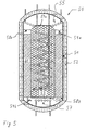
- FIG. 5 also shows a sorption memory according to the invention 50 in longitudinal section, in which the area 59, for stocking serves the condensate, the adsorber 53 encloses.
- This Arrangement is called a so-called tank-in-tank system.
- the adsorber 53 is tubular and like the sorption storage with its longitudinal axis along the longitudinal axis of the sorption storage 50 arranged in the middle.
- the sorption memory 50 also has a hermetically sealed seal Container 51 is with an external thermal insulation 52nd provided, and is like that shown in the other figures Sorption storage too, evacuated.
- a sorbent material preferably also silica gel and water used as the adsorbate.
- the adsorber 53 is a heat exchanger, as in the above explained sorption stores also integrated. Only at its upper and lower ends, the adsorber 53 has Water vapor permeable networks 57a and 57b connect to the Inside of the sorption memory 50. About the same amount as the network 57a, a condensation heat exchanger 55 is provided extends around the adsorber 53 so that above the network 57a no heat coil of the condensation heat exchanger 55 runs. A horizontal runs approximately at the level of the upper network 57a Partition 58a, which with the adsorber 53 and the wall of the Sorption storage 50 completes.
- a tank 59 for receiving condensed adsorbate is formed.
- the tank 59 has an electric top and bottom each from the outside controllable valve 59a or 59b, via which there is a connection with the upper condensation area or a connection controllable with the lower evaporation range leaves.
- the heat exchanger integrated in the adsorber 53 fed from a heat source. That adsorbed on the adsorber Adsorbate, preferably water, desorbed, the water vapor passes the water vapor permeable net 57a and arrives to the condensation heat exchanger 55.
- the condensation heat exchanger is connected to a heat sink and removes it flowing water vapor heat energy, the water vapor condenses and drips onto the upper partition 58 a.
- valve 59a which is in a Lower the upper partition 58a is located, the condensate flows into the tank 59, which concentrically surrounds the adsorber 53.
- valve 59a is closed, to prevent adsorbate that has already been desorbed from becoming uncontrolled from the tank back into the adsorber.
- the condensate flows through the valve 59b to a controlled extent into the evaporator, is from the evaporator heat exchanger 57, which with a Heat source is connected, evaporates and the water vapor flows via the water vapor permeable network 57b back into the adsorber 53 where it adsorbs.
- the adsorber heat exchanger Heat sink e.g. a domestic hot water tank or one Space heating
- Figure 6 shows a further embodiment of a sorption memory in a sectional view.
- the container shown is the internal structure compared to the examples shown so far simplified.
- a Heat exchanger adsorber WT-AD provided
- the lower part the container with a heat exchanger / evaporator / condenser / WT -VD / KD is equipped and between two chambers Valve V is located.
- a network N keeps the sorption material from Valve inlet area back.
- Via an evacuation nozzle S can simultaneous evacuation of the container interior and of the space for the vacuum insulation.
- the sorption material is taken up, the condensate being collected in the lower container section KD becomes.
Landscapes
- Engineering & Computer Science (AREA)
- Physics & Mathematics (AREA)
- Thermal Sciences (AREA)
- Mechanical Engineering (AREA)
- General Engineering & Computer Science (AREA)
- Chemical & Material Sciences (AREA)
- Chemical Kinetics & Catalysis (AREA)
- General Chemical & Material Sciences (AREA)
- Sorption Type Refrigeration Machines (AREA)
- Central Heating Systems (AREA)
Claims (19)
- Accumulateur à sorption (2a, 2b, 2c, 2d ; 30 ; 40 ; 50) destiné à stocker la chaleur, comprenant les caractéristiques suivantes :caractérisé en ce qu'un ou plusieurs réservoirs (31 ; 51) fermés hermétiquement ;le réservoir ou l'agencement (2) de réservoirs contiennent un ou plusieurs adsorbats ;le réservoir ou l'agencement de réservoirs comportent au moins une première et une deuxième zone (21, 22 ; 33, 39 ; 53, 59) ;la première zone (21 : 33 ; 53 ; KD) contient une matière de sorption destinée à adsorber le ou les adsorbats et formé une unité d'adsorption ;la deuxième zone (22 ; 39 ; 59 ; KB) est destinée à recevoir le ou les adsorbats condensés, qui sont libérés par désorption à partir de la matière de sorption,
une grille, ainsi qu'une zone d'entrée de soupape, munie d'une soupape (39a ; 48 ; 59a ; V) pouvant être commandée, sont disposées entre la première et la deuxième zone en forme de chambres en vue de former une séparation entre celles-ci, la première zone étant munie d'un ou plusieurs Echangeurs thermiques (36 ; WT) et la soupape étant disposée à l'intérieur du réservoir, en outre, le réservoir ou l'agencement de réservoirs sont vidés au moins jusqu'à un niveau tel que les pressions des gaz résiduels ne constituent sensiblement pas d'obstacle au transport du condensat évaporé vers l'unité d'adsorption. - Accumulateur à sorption selon la revendication 1,
caractérisé en ce que
le réservoir ou l'agencement de réservoirs comportent une troisième zone (34 ; 44 ; 55), qui forme un condenseur, dans lequel sont condensés le ou les adsorbats gazeux, et/ou forme un évaporateur (34 ; 44 ; 57) dans lequel l'adsorbat condensé, à savoir le condensat, s'évapore. - Accumulateur à sorption selon une ou plusieurs des revendications précédentes,
caractérisé en ce que
le ou les réservoirs sont réalisés selon une forme tubulaire. - Accumulateur à sorption selon une ou plusieurs des revendications précédentes,
caractérisé en ce que
le ou les réservoirs sont entourés d'une chemise en acier. - Accumulateur à sorption selon une ou plusieurs des revendications précédentes,
caractérisé en ce que
le ou les réservoirs sont revêtus d'un isolant thermique (32 ; 52) pour former une isolation thermique par rapport à l'environnement. - Accumulateur à sorption selon une ou plusieurs des revendications précédentes,
caractérisé en ce que
les un ou plusieurs adsorbats contiennent au moins, en partie de l'eau. - Accumulateur à sorption selon la revendication 6,
caractérisé en ce que
seule l'eau est utilisée comme adsorbat. - Accumulateur à sorption selon l'une des revendications 1 à 6,
caractérisé en ce que
les un ou plusieurs adsorbats contiennent au moins en partie de l'ammoniac. - Accumulateur à sorption selon une des revendications 1 à 5,
caractérisé en ce que
seul l'ammoniac est utilisé comme adsorbat. - Accumulateur à sorption selon une ou plusieurs des revendications précédentes,
caractérisé en ce que
la matière de sorption contient des adsorbants, en particulier tels que le charbon actif, le gel de silice ou la poudre d'alumine. - Accumulateur à sorption selon une ou plusieurs des revendications précédentes,
caractérisé en ce que
la matière de sorption est du gel de silice. - Accumulateur à sorption selon une ou plusieurs des revendications 2 à 11,
caractérisé en ce que,
entre le condenseur (39 ; 49 ; 59) et l'unité d'adsorption (33 ; 53), sont prévus un ou plusieurs échangeurs thermiques (35 ; 45) destinés à produire la condensation et/ou l'évaporation. - Accumulateur à sorption selon une ou plusieurs des revendications 2 à 12,
caractérisé en ce qu'
un échangeur thermique (47) est placé dans le condenseur (49) et est enveloppé par le condensat. - Accumulateur à sorption selon l'une des revendications 2 à 13,
caractérisé en ce que
la liaison entre l'unité d'adsorption et le condenseur est formée au moins en partie par un ou plusieurs tuyaux de montée (39b) disposés verticalement. - Accumulateur à sorption selon l'une des revendications 1 à 14,
caractérisé en ce qu'
une conduite de distribution (2p, 2q, 2s, 2t) préfabriqués est adaptée à la géométrie de l'accumulateur à sorption selon l'une des revendications précédentes, et en ce que la conduite de distribution permet de monter en série ou en parallèle les échangeurs thermiques (21u, 21v, 21w, 21x) de plusieurs accumulateurs à sorption (2a, 2b, 2c, 2d). - Agencement pour le stockage de chaleur dans un accumulateur à sorption selon l'une des revendications 1 à 14,
caractérisé en ce quel'unité d'adsorption ou les unités d'adsorption (21a, 21b, 21c, 21d) du ou des accumulateurs à sorption sont reliées à une ou plusieurs sources de chaleur (3, 6) par l'intermédiaire d'un ou plusieurs échangeurs thermiques (21u, 21v, 21w, 21x) au moment du chargement de l'accumulateur à sorption, etle ou les échangeurs thermiques (22u, 22v, 22w, 22x) du ou des condenseurs (22a, 22b, 22c, 22d) sont reliés à un ou plusieurs dissipateurs thermiques (7, 8, 9). - Agencement selon la revendication 16,
caractérisé en ce que
les sources de chaleur sont formées par des capteurs solaires (3) et/ou un réservoir d'eau industrielle (4, 8) et/ou un appareil de chauffage supplémentaire (6), tel qu'un chauffage au bols, et/ou une pompe à chaleur, et les dissipateurs de chaleur sont formés par un échangeur thermique souterrain et/ou un échangeur thermique à l'air libre (7) et/ou un réservoir d'eau Industrielle (8) et/ou un appareil de chauffage d'un local (9). - Procédé de stockage de chaleur et/ou de production de chaleur avec un accumulateur à sorption selon l'une des revendications 1 à 14,
caractérisé en ce queau cours d'une première étape, l'énergie thermique, fournie par une source de chaleur (3, 6), en particulier telle que des capteurs solaires (3) et/ou un appareil de chauffage supplémentaire (6), tel qu'une chaudière au bois, et/ou une pompe à chaleur, est acheminée, en particulier par l'intermédiaire d'un échangeur thermique (21u, 21v, 21w, 21x) placé dans l'unité d'adsorption, vers les unités d'adsorption (21a, 21b, 21c, 21d), qui comportent un agent d'adsorption contenant un adsorbat ;au cours d'une deuxième étape, en raison de l'énergie thermique acheminée vers l'unité d'adsorption, l'adsorbat est libéré par désorption à partir de l'agent d'adsorption, etau cours d'une troisième étape, l'adsorbat gazeux est condensé, le condensât est recueilli et l'énergie thermique générée à cet effet est acheminée vers un dissipateur de chaleur (7, 8, 9), tel qu'un réservoir d'eau industrielle (8), un appareil de chauffage d'un local (9) et/ou un échangeur thermique souterrain et/ou un échangeur thermique à l'air libre (7). - Procédé selon la revendication 18,
caractérisé en ce queau cours d'une quatrième étape, le condensat s'évapore et l'adsorbat gazeux est acheminé vers l'unité d'adsorption,au cours d'une cinquième étape, l'adsorbat est adsorbé par l'unité d'adsorptíon et de l'énergie thermique se dégage alors ; etl'énergie thermique dégagée est acheminée par l'intermédiaire d'un échangeur thermique vers le dissipateur de chaleur, en particulier tel qu'un appareil de chauffage d'un local et/ou un réservoir d'eau industrielle.
Applications Claiming Priority (11)
| Application Number | Priority Date | Filing Date | Title |
|---|---|---|---|
| DE19758427 | 1997-08-13 | ||
| DE19758427 | 1997-08-13 | ||
| DE19736259 | 1997-08-20 | ||
| DE19736259 | 1997-08-20 | ||
| DE19749866 | 1997-11-11 | ||
| DE19749866 | 1997-11-11 | ||
| DE19800442 | 1998-01-08 | ||
| DE19800442 | 1998-01-08 | ||
| DE19811302 | 1998-03-16 | ||
| DE19811302A DE19811302C2 (de) | 1997-08-13 | 1998-03-16 | Sorptionsspeicher, Anordnung und Verfahren zur Speicherung von Wärme |
| PCT/EP1998/004387 WO1999009365A1 (fr) | 1997-08-13 | 1998-07-14 | Accumulateur a sorption, dispositif et procede d'accumulation de chaleur |
Publications (2)
| Publication Number | Publication Date |
|---|---|
| EP1004001A1 EP1004001A1 (fr) | 2000-05-31 |
| EP1004001B1 true EP1004001B1 (fr) | 2003-03-05 |
Family
ID=27512593
Family Applications (1)
| Application Number | Title | Priority Date | Filing Date |
|---|---|---|---|
| EP98940226A Expired - Lifetime EP1004001B1 (fr) | 1997-08-13 | 1998-07-14 | Accumulateur a sorption, dispositif et procede d'accumulation de chaleur |
Country Status (4)
| Country | Link |
|---|---|
| EP (1) | EP1004001B1 (fr) |
| AT (1) | ATE233887T1 (fr) |
| AU (1) | AU8861898A (fr) |
| WO (1) | WO1999009365A1 (fr) |
Cited By (3)
| Publication number | Priority date | Publication date | Assignee | Title |
|---|---|---|---|---|
| DE202013100153U1 (de) | 2013-01-11 | 2013-02-11 | TAO Transatmospheric Operations GmbH | Sorptionsspeicherheizung |
| DE102013100294A1 (de) | 2013-01-11 | 2014-07-17 | TAO Transatmospheric Operations GmbH | Sorptionsspeicherheizung |
| DE102007050971B4 (de) * | 2007-03-14 | 2014-12-31 | BLüCHER GMBH | Verfahren zur Herstellung von Hochleistungsadsorbentien auf der Basis von Aktivkohle mit hoher Meso- und Makroporosität, Hochleistungsadsorbentien und deren Verwendung |
Families Citing this family (3)
| Publication number | Priority date | Publication date | Assignee | Title |
|---|---|---|---|---|
| DE19963322B4 (de) | 1999-12-21 | 2005-09-29 | Bernd Füsting | Sorptionswärmespeicher hoher Energiedichte |
| TWI318983B (en) * | 2000-05-02 | 2010-01-01 | Uab Research Foundation | An antibody selective for a tumor necrosis factor-related apoptosis-inducing ligand receptor and uses thereof |
| WO2015006666A1 (fr) * | 2013-07-11 | 2015-01-15 | Eos Energy Storage, Llc | Stockage d'énergie mécano-chimique |
Family Cites Families (6)
| Publication number | Priority date | Publication date | Assignee | Title |
|---|---|---|---|---|
| WO1985005170A1 (fr) * | 1984-05-01 | 1985-11-21 | Tchernev Dimiter I | Pompe de chaleur actionnee par une source thermique de faible intensite |
| CH609140A5 (fr) * | 1976-05-18 | 1979-02-15 | Sulzer Ag | |
| DE3207656A1 (de) * | 1982-02-15 | 1983-08-25 | Hieronimi, Ulrich, 8000 München | Sorptionsapparate und verfahren fuer ihren betrieb |
| DE3212608A1 (de) * | 1982-04-05 | 1983-10-06 | Georg Alefeld | Speicherheizungsanlage mit sorptionsspeicher |
| DE3532093C1 (de) * | 1985-09-09 | 1987-04-09 | Schiedel Gmbh & Co | Diskontinuierlich arbeitende Sorptions-Speichervorrichtung mit Feststoffabsorber |
| JPH0391660A (ja) * | 1989-09-04 | 1991-04-17 | Nishiyodo Kuuchiyouki Kk | 吸着式蓄熱装置及び該装置を利用した吸着式蓄熱システム |
-
1998
- 1998-07-14 WO PCT/EP1998/004387 patent/WO1999009365A1/fr not_active Ceased
- 1998-07-14 AU AU88618/98A patent/AU8861898A/en not_active Abandoned
- 1998-07-14 AT AT98940226T patent/ATE233887T1/de active
- 1998-07-14 EP EP98940226A patent/EP1004001B1/fr not_active Expired - Lifetime
Cited By (3)
| Publication number | Priority date | Publication date | Assignee | Title |
|---|---|---|---|---|
| DE102007050971B4 (de) * | 2007-03-14 | 2014-12-31 | BLüCHER GMBH | Verfahren zur Herstellung von Hochleistungsadsorbentien auf der Basis von Aktivkohle mit hoher Meso- und Makroporosität, Hochleistungsadsorbentien und deren Verwendung |
| DE202013100153U1 (de) | 2013-01-11 | 2013-02-11 | TAO Transatmospheric Operations GmbH | Sorptionsspeicherheizung |
| DE102013100294A1 (de) | 2013-01-11 | 2014-07-17 | TAO Transatmospheric Operations GmbH | Sorptionsspeicherheizung |
Also Published As
| Publication number | Publication date |
|---|---|
| EP1004001A1 (fr) | 2000-05-31 |
| AU8861898A (en) | 1999-03-08 |
| ATE233887T1 (de) | 2003-03-15 |
| WO1999009365A1 (fr) | 1999-02-25 |
Similar Documents
| Publication | Publication Date | Title |
|---|---|---|
| DE19811302C2 (de) | Sorptionsspeicher, Anordnung und Verfahren zur Speicherung von Wärme | |
| DE3633465C2 (fr) | ||
| EP1495272B1 (fr) | Pompe a chaleur a sorption solide | |
| EP0026257B1 (fr) | Installation comportant une pompe à chaleur à absorption | |
| DE69923792T2 (de) | Chemische wärmepumpe | |
| DE4019669C2 (de) | Adsorptionsthermischer Speicher | |
| WO2008034561A2 (fr) | pompe à chaleur à adsorption dotée d'un accumulateur de chaleur | |
| DE102008048655B4 (de) | Verfahren zum Transport von Wärme, Transportsystem für einen Wärmeträger sowie dessen Verwendung | |
| CH647590A5 (en) | Process and equipment for producing useful energy from low-grade heat sources | |
| DE19963322B4 (de) | Sorptionswärmespeicher hoher Energiedichte | |
| EP2643645A2 (fr) | Cuve à vide permettant d'éliminer les gaz étrangers d'une machine frigorifique à adsorption | |
| EP1004001B1 (fr) | Accumulateur a sorption, dispositif et procede d'accumulation de chaleur | |
| CH651915A5 (de) | Verfahren zur nutzung und speicherung von energie aus der umwelt. | |
| DE102012009696A1 (de) | System und Verfahren zur Erzeugung und /oder Speicherung von Wärme und /oder Kälte | |
| DE2622699A1 (de) | Speicherelement fuer ein sorptions- waermespeichersystem | |
| DE4219728A1 (de) | Thermisch aktives wandelement | |
| AT409232B (de) | Verdampfer/kondensator einer sorptionspumpe | |
| DE3146902A1 (de) | Heizanlage | |
| EP1150077B1 (fr) | Conteneur à sorption avec une enveloppe flexible | |
| DE4302281A1 (de) | Vorrichtung zur Aufnahme und Abgabe von Wärmeenergie | |
| DE19735007C9 (de) | Vorrichtung zur Speicherung und Abgabe von Wärme | |
| DE102013100294A1 (de) | Sorptionsspeicherheizung | |
| DE60024909T2 (de) | Verfahren zum Einbau einer Klimaanlage | |
| DE202013100153U1 (de) | Sorptionsspeicherheizung | |
| EP1896791B1 (fr) | Accumulateur de chaleur a haute densite d'accumulation |
Legal Events
| Date | Code | Title | Description |
|---|---|---|---|
| PUAI | Public reference made under article 153(3) epc to a published international application that has entered the european phase |
Free format text: ORIGINAL CODE: 0009012 |
|
| 17P | Request for examination filed |
Effective date: 19991118 |
|
| AK | Designated contracting states |
Kind code of ref document: A1 Designated state(s): AT CH DE DK FI FR IT LI NL SE |
|
| 17Q | First examination report despatched |
Effective date: 20010313 |
|
| RAP1 | Party data changed (applicant data changed or rights of an application transferred) |
Owner name: SORTECH AG I.GR. |
|
| GRAH | Despatch of communication of intention to grant a patent |
Free format text: ORIGINAL CODE: EPIDOS IGRA |
|
| GRAH | Despatch of communication of intention to grant a patent |
Free format text: ORIGINAL CODE: EPIDOS IGRA |
|
| GRAA | (expected) grant |
Free format text: ORIGINAL CODE: 0009210 |
|
| AK | Designated contracting states |
Designated state(s): AT CH DE DK FI FR IT LI NL SE |
|
| PG25 | Lapsed in a contracting state [announced via postgrant information from national office to epo] |
Ref country code: IT Free format text: LAPSE BECAUSE OF FAILURE TO SUBMIT A TRANSLATION OF THE DESCRIPTION OR TO PAY THE FEE WITHIN THE PRE;WARNING: LAPSES OF ITALIAN PATENTS WITH EFFECTIVE DATE BEFORE 2007 MAY HAVE OCCURRED AT ANY TIME BEFORE 2007. THE CORRECT EFFECTIVE DATE MAY BE DIFFERENT FROM THE ONE RECORDED.SCRIBED TIME-LIMIT Effective date: 20030305 |
|
| REG | Reference to a national code |
Ref country code: CH Ref legal event code: EP |
|
| REF | Corresponds to: |
Ref document number: 59807401 Country of ref document: DE Date of ref document: 20030410 Kind code of ref document: P |
|
| REG | Reference to a national code |
Ref country code: SE Ref legal event code: TRGR |
|
| PG25 | Lapsed in a contracting state [announced via postgrant information from national office to epo] |
Ref country code: DK Free format text: LAPSE BECAUSE OF FAILURE TO SUBMIT A TRANSLATION OF THE DESCRIPTION OR TO PAY THE FEE WITHIN THE PRESCRIBED TIME-LIMIT Effective date: 20030605 |
|
| PG25 | Lapsed in a contracting state [announced via postgrant information from national office to epo] |
Ref country code: LI Free format text: LAPSE BECAUSE OF NON-PAYMENT OF DUE FEES Effective date: 20030731 Ref country code: CH Free format text: LAPSE BECAUSE OF NON-PAYMENT OF DUE FEES Effective date: 20030731 |
|
| ET | Fr: translation filed | ||
| PLBE | No opposition filed within time limit |
Free format text: ORIGINAL CODE: 0009261 |
|
| STAA | Information on the status of an ep patent application or granted ep patent |
Free format text: STATUS: NO OPPOSITION FILED WITHIN TIME LIMIT |
|
| PG25 | Lapsed in a contracting state [announced via postgrant information from national office to epo] |
Ref country code: DE Free format text: LAPSE BECAUSE OF NON-PAYMENT OF DUE FEES Effective date: 20040203 |
|
| 26N | No opposition filed |
Effective date: 20031208 |
|
| REG | Reference to a national code |
Ref country code: CH Ref legal event code: PL |
|
| PGFP | Annual fee paid to national office [announced via postgrant information from national office to epo] |
Ref country code: NL Payment date: 20080722 Year of fee payment: 11 Ref country code: FI Payment date: 20080714 Year of fee payment: 11 |
|
| PGFP | Annual fee paid to national office [announced via postgrant information from national office to epo] |
Ref country code: SE Payment date: 20080704 Year of fee payment: 11 |
|
| EUG | Se: european patent has lapsed | ||
| NLV4 | Nl: lapsed or anulled due to non-payment of the annual fee |
Effective date: 20100201 |
|
| PG25 | Lapsed in a contracting state [announced via postgrant information from national office to epo] |
Ref country code: FI Free format text: LAPSE BECAUSE OF NON-PAYMENT OF DUE FEES Effective date: 20090714 |
|
| PG25 | Lapsed in a contracting state [announced via postgrant information from national office to epo] |
Ref country code: SE Free format text: LAPSE BECAUSE OF NON-PAYMENT OF DUE FEES Effective date: 20090715 |
|
| PG25 | Lapsed in a contracting state [announced via postgrant information from national office to epo] |
Ref country code: NL Free format text: LAPSE BECAUSE OF NON-PAYMENT OF DUE FEES Effective date: 20100201 |
|
| REG | Reference to a national code |
Ref country code: FR Ref legal event code: PLFP Year of fee payment: 18 |
|
| PGFP | Annual fee paid to national office [announced via postgrant information from national office to epo] |
Ref country code: AT Payment date: 20150729 Year of fee payment: 18 Ref country code: FR Payment date: 20150630 Year of fee payment: 18 |
|
| REG | Reference to a national code |
Ref country code: AT Ref legal event code: MM01 Ref document number: 233887 Country of ref document: AT Kind code of ref document: T Effective date: 20160714 |
|
| PG25 | Lapsed in a contracting state [announced via postgrant information from national office to epo] |
Ref country code: FR Free format text: LAPSE BECAUSE OF NON-PAYMENT OF DUE FEES Effective date: 20160801 |
|
| REG | Reference to a national code |
Ref country code: FR Ref legal event code: ST Effective date: 20170331 |
|
| PG25 | Lapsed in a contracting state [announced via postgrant information from national office to epo] |
Ref country code: AT Free format text: LAPSE BECAUSE OF NON-PAYMENT OF DUE FEES Effective date: 20160714 |