EP1004015B1 - Dispositif permettant de realiser des dosages au niveau de sites reactionnels - Google Patents
Dispositif permettant de realiser des dosages au niveau de sites reactionnels Download PDFInfo
- Publication number
- EP1004015B1 EP1004015B1 EP98942073A EP98942073A EP1004015B1 EP 1004015 B1 EP1004015 B1 EP 1004015B1 EP 98942073 A EP98942073 A EP 98942073A EP 98942073 A EP98942073 A EP 98942073A EP 1004015 B1 EP1004015 B1 EP 1004015B1
- Authority
- EP
- European Patent Office
- Prior art keywords
- fluid
- substrate
- dispenser
- reaction sites
- reaction
- Prior art date
- Legal status (The legal status is an assumption and is not a legal conclusion. Google has not performed a legal analysis and makes no representation as to the accuracy of the status listed.)
- Expired - Lifetime
Links
- 238000006243 chemical reaction Methods 0.000 title claims abstract description 227
- 238000003556 assay Methods 0.000 title claims abstract description 30
- 239000012530 fluid Substances 0.000 claims abstract description 348
- 239000000758 substrate Substances 0.000 claims abstract description 178
- 239000000463 material Substances 0.000 claims abstract description 21
- 230000033001 locomotion Effects 0.000 claims abstract description 17
- 239000004065 semiconductor Substances 0.000 claims abstract description 13
- 239000000835 fiber Substances 0.000 claims description 46
- 239000000126 substance Substances 0.000 claims description 45
- 230000007246 mechanism Effects 0.000 claims description 18
- 238000001514 detection method Methods 0.000 claims description 14
- 239000007787 solid Substances 0.000 claims description 10
- 239000000523 sample Substances 0.000 claims description 9
- 238000003491 array Methods 0.000 claims description 8
- 239000011521 glass Substances 0.000 claims description 6
- 239000011324 bead Substances 0.000 claims description 5
- 239000004033 plastic Substances 0.000 claims description 3
- 229920003023 plastic Polymers 0.000 claims description 3
- 239000000919 ceramic Substances 0.000 claims description 2
- 239000002131 composite material Substances 0.000 claims description 2
- 230000005684 electric field Effects 0.000 claims description 2
- 238000010438 heat treatment Methods 0.000 claims description 2
- 230000001133 acceleration Effects 0.000 claims 1
- 230000004888 barrier function Effects 0.000 claims 1
- 238000011144 upstream manufacturing Methods 0.000 claims 1
- 230000006870 function Effects 0.000 abstract description 14
- 230000009977 dual effect Effects 0.000 abstract description 3
- 238000012360 testing method Methods 0.000 description 30
- XUIMIQQOPSSXEZ-UHFFFAOYSA-N Silicon Chemical compound [Si] XUIMIQQOPSSXEZ-UHFFFAOYSA-N 0.000 description 25
- 239000013307 optical fiber Substances 0.000 description 25
- 229910052710 silicon Inorganic materials 0.000 description 25
- 239000010703 silicon Substances 0.000 description 25
- 238000000034 method Methods 0.000 description 18
- 239000000243 solution Substances 0.000 description 15
- 239000003570 air Substances 0.000 description 14
- 230000008901 benefit Effects 0.000 description 11
- 238000005842 biochemical reaction Methods 0.000 description 11
- 238000001704 evaporation Methods 0.000 description 10
- 230000008020 evaporation Effects 0.000 description 10
- 239000006185 dispersion Substances 0.000 description 9
- 230000000694 effects Effects 0.000 description 9
- 238000004458 analytical method Methods 0.000 description 8
- PYWVYCXTNDRMGF-UHFFFAOYSA-N rhodamine B Chemical compound [Cl-].C=12C=CC(=[N+](CC)CC)C=C2OC2=CC(N(CC)CC)=CC=C2C=1C1=CC=CC=C1C(O)=O PYWVYCXTNDRMGF-UHFFFAOYSA-N 0.000 description 8
- 238000012546 transfer Methods 0.000 description 8
- 238000012544 monitoring process Methods 0.000 description 7
- 230000001276 controlling effect Effects 0.000 description 6
- 238000005516 engineering process Methods 0.000 description 6
- 150000002500 ions Chemical class 0.000 description 6
- 239000000203 mixture Substances 0.000 description 6
- 230000008569 process Effects 0.000 description 6
- 238000005070 sampling Methods 0.000 description 6
- 238000012216 screening Methods 0.000 description 6
- 239000002904 solvent Substances 0.000 description 6
- 239000012298 atmosphere Substances 0.000 description 5
- 230000003993 interaction Effects 0.000 description 5
- KRHYYFGTRYWZRS-UHFFFAOYSA-N Fluorane Chemical compound F KRHYYFGTRYWZRS-UHFFFAOYSA-N 0.000 description 4
- 241000233855 Orchidaceae Species 0.000 description 4
- 210000004027 cell Anatomy 0.000 description 4
- 239000000428 dust Substances 0.000 description 4
- 230000005284 excitation Effects 0.000 description 4
- 230000003287 optical effect Effects 0.000 description 4
- 229920002120 photoresistant polymer Polymers 0.000 description 4
- 239000000047 product Substances 0.000 description 4
- 108090000623 proteins and genes Proteins 0.000 description 4
- 238000005086 pumping Methods 0.000 description 4
- 230000002441 reversible effect Effects 0.000 description 4
- CVAVMIODJQHEEH-UHFFFAOYSA-O rhodamine B(1+) Chemical compound C=12C=CC(=[N+](CC)CC)C=C2OC2=CC(N(CC)CC)=CC=C2C=1C1=CC=CC=C1C(O)=O CVAVMIODJQHEEH-UHFFFAOYSA-O 0.000 description 4
- 238000000926 separation method Methods 0.000 description 4
- CSCPPACGZOOCGX-UHFFFAOYSA-N Acetone Chemical compound CC(C)=O CSCPPACGZOOCGX-UHFFFAOYSA-N 0.000 description 3
- -1 and in particular Substances 0.000 description 3
- 239000006117 anti-reflective coating Substances 0.000 description 3
- 150000001875 compounds Chemical class 0.000 description 3
- 230000007423 decrease Effects 0.000 description 3
- 238000010790 dilution Methods 0.000 description 3
- 239000012895 dilution Substances 0.000 description 3
- 238000001962 electrophoresis Methods 0.000 description 3
- 238000012986 modification Methods 0.000 description 3
- 230000004048 modification Effects 0.000 description 3
- 239000003921 oil Substances 0.000 description 3
- 102000004169 proteins and genes Human genes 0.000 description 3
- XLYOFNOQVPJJNP-UHFFFAOYSA-N water Substances O XLYOFNOQVPJJNP-UHFFFAOYSA-N 0.000 description 3
- 108091032973 (ribonucleotides)n+m Proteins 0.000 description 2
- 108020004414 DNA Proteins 0.000 description 2
- 102000004190 Enzymes Human genes 0.000 description 2
- 108090000790 Enzymes Proteins 0.000 description 2
- NYHBQMYGNKIUIF-UUOKFMHZSA-N Guanosine Chemical compound C1=NC=2C(=O)NC(N)=NC=2N1[C@@H]1O[C@H](CO)[C@@H](O)[C@H]1O NYHBQMYGNKIUIF-UUOKFMHZSA-N 0.000 description 2
- LRHPLDYGYMQRHN-UHFFFAOYSA-N N-Butanol Chemical compound CCCCO LRHPLDYGYMQRHN-UHFFFAOYSA-N 0.000 description 2
- 240000004808 Saccharomyces cerevisiae Species 0.000 description 2
- IQFYYKKMVGJFEH-XLPZGREQSA-N Thymidine Chemical compound O=C1NC(=O)C(C)=CN1[C@@H]1O[C@H](CO)[C@@H](O)C1 IQFYYKKMVGJFEH-XLPZGREQSA-N 0.000 description 2
- ISAKRJDGNUQOIC-UHFFFAOYSA-N Uracil Chemical compound O=C1C=CNC(=O)N1 ISAKRJDGNUQOIC-UHFFFAOYSA-N 0.000 description 2
- OIRDTQYFTABQOQ-KQYNXXCUSA-N adenosine Chemical compound C1=NC=2C(N)=NC=NC=2N1[C@@H]1O[C@H](CO)[C@@H](O)[C@H]1O OIRDTQYFTABQOQ-KQYNXXCUSA-N 0.000 description 2
- 230000002411 adverse Effects 0.000 description 2
- 238000010876 biochemical test Methods 0.000 description 2
- 239000012472 biological sample Substances 0.000 description 2
- 230000005540 biological transmission Effects 0.000 description 2
- 239000000872 buffer Substances 0.000 description 2
- 239000007795 chemical reaction product Substances 0.000 description 2
- 239000003153 chemical reaction reagent Substances 0.000 description 2
- 238000007705 chemical test Methods 0.000 description 2
- 238000000576 coating method Methods 0.000 description 2
- 230000000875 corresponding effect Effects 0.000 description 2
- OPTASPLRGRRNAP-UHFFFAOYSA-N cytosine Chemical compound NC=1C=CNC(=O)N=1 OPTASPLRGRRNAP-UHFFFAOYSA-N 0.000 description 2
- 230000001419 dependent effect Effects 0.000 description 2
- 238000000151 deposition Methods 0.000 description 2
- 230000005686 electrostatic field Effects 0.000 description 2
- 230000014509 gene expression Effects 0.000 description 2
- 239000013067 intermediate product Substances 0.000 description 2
- 238000012423 maintenance Methods 0.000 description 2
- 230000014759 maintenance of location Effects 0.000 description 2
- 210000004962 mammalian cell Anatomy 0.000 description 2
- 238000004519 manufacturing process Methods 0.000 description 2
- 239000012528 membrane Substances 0.000 description 2
- 238000005459 micromachining Methods 0.000 description 2
- 238000002156 mixing Methods 0.000 description 2
- 239000002777 nucleoside Substances 0.000 description 2
- 125000003835 nucleoside group Chemical group 0.000 description 2
- 239000002773 nucleotide Substances 0.000 description 2
- 125000003729 nucleotide group Chemical group 0.000 description 2
- BASFCYQUMIYNBI-UHFFFAOYSA-N platinum Chemical compound [Pt] BASFCYQUMIYNBI-UHFFFAOYSA-N 0.000 description 2
- 230000009467 reduction Effects 0.000 description 2
- 238000011160 research Methods 0.000 description 2
- 230000004044 response Effects 0.000 description 2
- 230000000717 retained effect Effects 0.000 description 2
- 238000007789 sealing Methods 0.000 description 2
- 238000013519 translation Methods 0.000 description 2
- 102000009091 Amyloidogenic Proteins Human genes 0.000 description 1
- 108010048112 Amyloidogenic Proteins Proteins 0.000 description 1
- 101001007348 Arachis hypogaea Galactose-binding lectin Proteins 0.000 description 1
- 241000271566 Aves Species 0.000 description 1
- 241000894006 Bacteria Species 0.000 description 1
- DWRXFEITVBNRMK-UHFFFAOYSA-N Beta-D-1-Arabinofuranosylthymine Natural products O=C1NC(=O)C(C)=CN1C1C(O)C(O)C(CO)O1 DWRXFEITVBNRMK-UHFFFAOYSA-N 0.000 description 1
- 239000002126 C01EB10 - Adenosine Substances 0.000 description 1
- 108091060290 Chromatid Proteins 0.000 description 1
- MIKUYHXYGGJMLM-GIMIYPNGSA-N Crotonoside Natural products C1=NC2=C(N)NC(=O)N=C2N1[C@H]1O[C@@H](CO)[C@H](O)[C@@H]1O MIKUYHXYGGJMLM-GIMIYPNGSA-N 0.000 description 1
- NYHBQMYGNKIUIF-UHFFFAOYSA-N D-guanosine Natural products C1=2NC(N)=NC(=O)C=2N=CN1C1OC(CO)C(O)C1O NYHBQMYGNKIUIF-UHFFFAOYSA-N 0.000 description 1
- 241000196324 Embryophyta Species 0.000 description 1
- 241000238631 Hexapoda Species 0.000 description 1
- 102000008394 Immunoglobulin Fragments Human genes 0.000 description 1
- 108010021625 Immunoglobulin Fragments Proteins 0.000 description 1
- 108091034117 Oligonucleotide Proteins 0.000 description 1
- 102000015636 Oligopeptides Human genes 0.000 description 1
- 108010038807 Oligopeptides Proteins 0.000 description 1
- ATJFFYVFTNAWJD-UHFFFAOYSA-N Tin Chemical compound [Sn] ATJFFYVFTNAWJD-UHFFFAOYSA-N 0.000 description 1
- RTAQQCXQSZGOHL-UHFFFAOYSA-N Titanium Chemical compound [Ti] RTAQQCXQSZGOHL-UHFFFAOYSA-N 0.000 description 1
- 241000700605 Viruses Species 0.000 description 1
- HCHKCACWOHOZIP-UHFFFAOYSA-N Zinc Chemical compound [Zn] HCHKCACWOHOZIP-UHFFFAOYSA-N 0.000 description 1
- GZFMWASBMSLFDX-UHFFFAOYSA-N [9-(2-carboxyphenyl)-6-(diethylamino)xanthen-3-ylidene]-diethylazanium;perchlorate Chemical compound [O-]Cl(=O)(=O)=O.C=12C=CC(=[N+](CC)CC)C=C2OC2=CC(N(CC)CC)=CC=C2C=1C1=CC=CC=C1C(O)=O GZFMWASBMSLFDX-UHFFFAOYSA-N 0.000 description 1
- 238000002835 absorbance Methods 0.000 description 1
- 230000003213 activating effect Effects 0.000 description 1
- 230000006978 adaptation Effects 0.000 description 1
- 229960005305 adenosine Drugs 0.000 description 1
- WYTGDNHDOZPMIW-RCBQFDQVSA-N alstonine Natural products C1=CC2=C3C=CC=CC3=NC2=C2N1C[C@H]1[C@H](C)OC=C(C(=O)OC)[C@H]1C2 WYTGDNHDOZPMIW-RCBQFDQVSA-N 0.000 description 1
- 239000012080 ambient air Substances 0.000 description 1
- 210000004102 animal cell Anatomy 0.000 description 1
- QVGXLLKOCUKJST-UHFFFAOYSA-N atomic oxygen Chemical compound [O] QVGXLLKOCUKJST-UHFFFAOYSA-N 0.000 description 1
- 230000001580 bacterial effect Effects 0.000 description 1
- IQFYYKKMVGJFEH-UHFFFAOYSA-N beta-L-thymidine Natural products O=C1NC(=O)C(C)=CN1C1OC(CO)C(O)C1 IQFYYKKMVGJFEH-UHFFFAOYSA-N 0.000 description 1
- 230000000975 bioactive effect Effects 0.000 description 1
- 230000015572 biosynthetic process Effects 0.000 description 1
- 230000000903 blocking effect Effects 0.000 description 1
- 210000001124 body fluid Anatomy 0.000 description 1
- 150000001720 carbohydrates Chemical class 0.000 description 1
- 235000014633 carbohydrates Nutrition 0.000 description 1
- 230000015556 catabolic process Effects 0.000 description 1
- 238000000423 cell based assay Methods 0.000 description 1
- 210000000170 cell membrane Anatomy 0.000 description 1
- 230000001413 cellular effect Effects 0.000 description 1
- 210000003850 cellular structure Anatomy 0.000 description 1
- 230000008859 change Effects 0.000 description 1
- 238000003486 chemical etching Methods 0.000 description 1
- 239000003795 chemical substances by application Substances 0.000 description 1
- 238000013098 chemical test method Methods 0.000 description 1
- 210000004756 chromatid Anatomy 0.000 description 1
- 210000000349 chromosome Anatomy 0.000 description 1
- 238000002983 circular dichroism Methods 0.000 description 1
- 238000004140 cleaning Methods 0.000 description 1
- 239000011248 coating agent Substances 0.000 description 1
- 238000004891 communication Methods 0.000 description 1
- 239000002299 complementary DNA Substances 0.000 description 1
- 238000009833 condensation Methods 0.000 description 1
- 230000005494 condensation Effects 0.000 description 1
- 239000004020 conductor Substances 0.000 description 1
- 238000010276 construction Methods 0.000 description 1
- 230000002596 correlated effect Effects 0.000 description 1
- 230000008878 coupling Effects 0.000 description 1
- 238000010168 coupling process Methods 0.000 description 1
- 238000005859 coupling reaction Methods 0.000 description 1
- 238000012864 cross contamination Methods 0.000 description 1
- 239000002178 crystalline material Substances 0.000 description 1
- 230000001186 cumulative effect Effects 0.000 description 1
- 238000005520 cutting process Methods 0.000 description 1
- 102000003675 cytokine receptors Human genes 0.000 description 1
- 108010057085 cytokine receptors Proteins 0.000 description 1
- 229940104302 cytosine Drugs 0.000 description 1
- 238000013016 damping Methods 0.000 description 1
- 238000007405 data analysis Methods 0.000 description 1
- 238000013500 data storage Methods 0.000 description 1
- 230000003247 decreasing effect Effects 0.000 description 1
- 238000006731 degradation reaction Methods 0.000 description 1
- 239000008367 deionised water Substances 0.000 description 1
- 229910021641 deionized water Inorganic materials 0.000 description 1
- 238000011161 development Methods 0.000 description 1
- 238000010586 diagram Methods 0.000 description 1
- HTXDPTMKBJXEOW-UHFFFAOYSA-N dioxoiridium Chemical compound O=[Ir]=O HTXDPTMKBJXEOW-UHFFFAOYSA-N 0.000 description 1
- 229940079593 drug Drugs 0.000 description 1
- 239000003814 drug Substances 0.000 description 1
- 238000007876 drug discovery Methods 0.000 description 1
- 238000007877 drug screening Methods 0.000 description 1
- 230000005672 electromagnetic field Effects 0.000 description 1
- 238000005370 electroosmosis Methods 0.000 description 1
- 230000007613 environmental effect Effects 0.000 description 1
- 238000005530 etching Methods 0.000 description 1
- 210000003527 eukaryotic cell Anatomy 0.000 description 1
- 210000002744 extracellular matrix Anatomy 0.000 description 1
- 238000013213 extrapolation Methods 0.000 description 1
- 238000012921 fluorescence analysis Methods 0.000 description 1
- 230000002538 fungal effect Effects 0.000 description 1
- 239000007789 gas Substances 0.000 description 1
- 230000002068 genetic effect Effects 0.000 description 1
- 229910052732 germanium Inorganic materials 0.000 description 1
- GNPVGFCGXDBREM-UHFFFAOYSA-N germanium atom Chemical compound [Ge] GNPVGFCGXDBREM-UHFFFAOYSA-N 0.000 description 1
- PCHJSUWPFVWCPO-UHFFFAOYSA-N gold Chemical compound [Au] PCHJSUWPFVWCPO-UHFFFAOYSA-N 0.000 description 1
- 229910052737 gold Inorganic materials 0.000 description 1
- 239000010931 gold Substances 0.000 description 1
- 229940029575 guanosine Drugs 0.000 description 1
- 238000013537 high throughput screening Methods 0.000 description 1
- 238000009396 hybridization Methods 0.000 description 1
- 230000000977 initiatory effect Effects 0.000 description 1
- 239000012212 insulator Substances 0.000 description 1
- 229910000457 iridium oxide Inorganic materials 0.000 description 1
- 150000002632 lipids Chemical class 0.000 description 1
- 238000004020 luminiscence type Methods 0.000 description 1
- 229910052751 metal Inorganic materials 0.000 description 1
- 239000002184 metal Substances 0.000 description 1
- 229910021645 metal ion Inorganic materials 0.000 description 1
- 150000002739 metals Chemical class 0.000 description 1
- 244000005700 microbiome Species 0.000 description 1
- 238000004377 microelectronic Methods 0.000 description 1
- 210000003470 mitochondria Anatomy 0.000 description 1
- 229910000484 niobium oxide Inorganic materials 0.000 description 1
- URLJKFSTXLNXLG-UHFFFAOYSA-N niobium(5+);oxygen(2-) Chemical compound [O-2].[O-2].[O-2].[O-2].[O-2].[Nb+5].[Nb+5] URLJKFSTXLNXLG-UHFFFAOYSA-N 0.000 description 1
- 239000012299 nitrogen atmosphere Substances 0.000 description 1
- 229910052756 noble gas Inorganic materials 0.000 description 1
- 108020004707 nucleic acids Proteins 0.000 description 1
- 102000039446 nucleic acids Human genes 0.000 description 1
- 150000007523 nucleic acids Chemical class 0.000 description 1
- 238000011022 operating instruction Methods 0.000 description 1
- 150000002894 organic compounds Chemical class 0.000 description 1
- 239000001301 oxygen Substances 0.000 description 1
- 229910052760 oxygen Inorganic materials 0.000 description 1
- 230000000737 periodic effect Effects 0.000 description 1
- 230000002093 peripheral effect Effects 0.000 description 1
- 239000013612 plasmid Substances 0.000 description 1
- 239000002985 plastic film Substances 0.000 description 1
- 229920006255 plastic film Polymers 0.000 description 1
- 229910052697 platinum Inorganic materials 0.000 description 1
- 229920000642 polymer Polymers 0.000 description 1
- 108091033319 polynucleotide Proteins 0.000 description 1
- 102000040430 polynucleotide Human genes 0.000 description 1
- 239000002157 polynucleotide Substances 0.000 description 1
- CHWRSCGUEQEHOH-UHFFFAOYSA-N potassium oxide Chemical compound [O-2].[K+].[K+] CHWRSCGUEQEHOH-UHFFFAOYSA-N 0.000 description 1
- 229910001950 potassium oxide Inorganic materials 0.000 description 1
- 230000002265 prevention Effects 0.000 description 1
- 102000004196 processed proteins & peptides Human genes 0.000 description 1
- 108090000765 processed proteins & peptides Proteins 0.000 description 1
- 210000001236 prokaryotic cell Anatomy 0.000 description 1
- 230000005855 radiation Effects 0.000 description 1
- 239000000376 reactant Substances 0.000 description 1
- 230000035484 reaction time Effects 0.000 description 1
- 238000004064 recycling Methods 0.000 description 1
- 230000002829 reductive effect Effects 0.000 description 1
- 230000001105 regulatory effect Effects 0.000 description 1
- 230000003362 replicative effect Effects 0.000 description 1
- 238000000518 rheometry Methods 0.000 description 1
- 210000003705 ribosome Anatomy 0.000 description 1
- 150000003839 salts Chemical class 0.000 description 1
- 230000035945 sensitivity Effects 0.000 description 1
- 210000002966 serum Anatomy 0.000 description 1
- 230000007480 spreading Effects 0.000 description 1
- 238000003892 spreading Methods 0.000 description 1
- 238000000992 sputter etching Methods 0.000 description 1
- 238000003756 stirring Methods 0.000 description 1
- 238000003860 storage Methods 0.000 description 1
- 238000002198 surface plasmon resonance spectroscopy Methods 0.000 description 1
- 239000004094 surface-active agent Substances 0.000 description 1
- 238000003786 synthesis reaction Methods 0.000 description 1
- 230000009885 systemic effect Effects 0.000 description 1
- 229940104230 thymidine Drugs 0.000 description 1
- 229910052719 titanium Inorganic materials 0.000 description 1
- 239000010936 titanium Substances 0.000 description 1
- 229940035893 uracil Drugs 0.000 description 1
- 239000011782 vitamin Substances 0.000 description 1
- 229940088594 vitamin Drugs 0.000 description 1
- 229930003231 vitamin Natural products 0.000 description 1
- 235000013343 vitamin Nutrition 0.000 description 1
- 238000009736 wetting Methods 0.000 description 1
- 229910052725 zinc Inorganic materials 0.000 description 1
- 239000011701 zinc Substances 0.000 description 1
Images








Classifications
-
- G—PHYSICS
- G01—MEASURING; TESTING
- G01N—INVESTIGATING OR ANALYSING MATERIALS BY DETERMINING THEIR CHEMICAL OR PHYSICAL PROPERTIES
- G01N35/00—Automatic analysis not limited to methods or materials provided for in any single one of groups G01N1/00 - G01N33/00; Handling materials therefor
- G01N35/02—Automatic analysis not limited to methods or materials provided for in any single one of groups G01N1/00 - G01N33/00; Handling materials therefor using a plurality of sample containers moved by a conveyor system past one or more treatment or analysis stations
- G01N35/025—Automatic analysis not limited to methods or materials provided for in any single one of groups G01N1/00 - G01N33/00; Handling materials therefor using a plurality of sample containers moved by a conveyor system past one or more treatment or analysis stations having a carousel or turntable for reaction cells or cuvettes
-
- B—PERFORMING OPERATIONS; TRANSPORTING
- B01—PHYSICAL OR CHEMICAL PROCESSES OR APPARATUS IN GENERAL
- B01J—CHEMICAL OR PHYSICAL PROCESSES, e.g. CATALYSIS OR COLLOID CHEMISTRY; THEIR RELEVANT APPARATUS
- B01J19/00—Chemical, physical or physico-chemical processes in general; Their relevant apparatus
- B01J19/0046—Sequential or parallel reactions, e.g. for the synthesis of polypeptides or polynucleotides; Apparatus and devices for combinatorial chemistry or for making molecular arrays
-
- G—PHYSICS
- G01—MEASURING; TESTING
- G01N—INVESTIGATING OR ANALYSING MATERIALS BY DETERMINING THEIR CHEMICAL OR PHYSICAL PROPERTIES
- G01N21/00—Investigating or analysing materials by the use of optical means, i.e. using sub-millimetre waves, infrared, visible or ultraviolet light
- G01N21/01—Arrangements or apparatus for facilitating the optical investigation
- G01N21/03—Cuvette constructions
- G01N21/07—Centrifugal type cuvettes
-
- G—PHYSICS
- G01—MEASURING; TESTING
- G01N—INVESTIGATING OR ANALYSING MATERIALS BY DETERMINING THEIR CHEMICAL OR PHYSICAL PROPERTIES
- G01N35/00—Automatic analysis not limited to methods or materials provided for in any single one of groups G01N1/00 - G01N33/00; Handling materials therefor
- G01N35/00029—Automatic analysis not limited to methods or materials provided for in any single one of groups G01N1/00 - G01N33/00; Handling materials therefor provided with flat sample substrates, e.g. slides
- G01N35/00069—Automatic analysis not limited to methods or materials provided for in any single one of groups G01N1/00 - G01N33/00; Handling materials therefor provided with flat sample substrates, e.g. slides whereby the sample substrate is of the bio-disk type, i.e. having the format of an optical disk
-
- B—PERFORMING OPERATIONS; TRANSPORTING
- B01—PHYSICAL OR CHEMICAL PROCESSES OR APPARATUS IN GENERAL
- B01J—CHEMICAL OR PHYSICAL PROCESSES, e.g. CATALYSIS OR COLLOID CHEMISTRY; THEIR RELEVANT APPARATUS
- B01J2219/00—Chemical, physical or physico-chemical processes in general; Their relevant apparatus
- B01J2219/00274—Sequential or parallel reactions; Apparatus and devices for combinatorial chemistry or for making arrays; Chemical library technology
- B01J2219/00277—Apparatus
- B01J2219/00279—Features relating to reactor vessels
- B01J2219/00306—Reactor vessels in a multiple arrangement
- B01J2219/00313—Reactor vessels in a multiple arrangement the reactor vessels being formed by arrays of wells in blocks
- B01J2219/00315—Microtiter plates
- B01J2219/00317—Microwell devices, i.e. having large numbers of wells
-
- B—PERFORMING OPERATIONS; TRANSPORTING
- B01—PHYSICAL OR CHEMICAL PROCESSES OR APPARATUS IN GENERAL
- B01J—CHEMICAL OR PHYSICAL PROCESSES, e.g. CATALYSIS OR COLLOID CHEMISTRY; THEIR RELEVANT APPARATUS
- B01J2219/00—Chemical, physical or physico-chemical processes in general; Their relevant apparatus
- B01J2219/00274—Sequential or parallel reactions; Apparatus and devices for combinatorial chemistry or for making arrays; Chemical library technology
- B01J2219/00277—Apparatus
- B01J2219/00351—Means for dispensing and evacuation of reagents
- B01J2219/00364—Pipettes
- B01J2219/00367—Pipettes capillary
-
- B—PERFORMING OPERATIONS; TRANSPORTING
- B01—PHYSICAL OR CHEMICAL PROCESSES OR APPARATUS IN GENERAL
- B01J—CHEMICAL OR PHYSICAL PROCESSES, e.g. CATALYSIS OR COLLOID CHEMISTRY; THEIR RELEVANT APPARATUS
- B01J2219/00—Chemical, physical or physico-chemical processes in general; Their relevant apparatus
- B01J2219/00274—Sequential or parallel reactions; Apparatus and devices for combinatorial chemistry or for making arrays; Chemical library technology
- B01J2219/00277—Apparatus
- B01J2219/00497—Features relating to the solid phase supports
- B01J2219/00527—Sheets
- B01J2219/00536—Sheets in the shape of disks
-
- B—PERFORMING OPERATIONS; TRANSPORTING
- B01—PHYSICAL OR CHEMICAL PROCESSES OR APPARATUS IN GENERAL
- B01J—CHEMICAL OR PHYSICAL PROCESSES, e.g. CATALYSIS OR COLLOID CHEMISTRY; THEIR RELEVANT APPARATUS
- B01J2219/00—Chemical, physical or physico-chemical processes in general; Their relevant apparatus
- B01J2219/00274—Sequential or parallel reactions; Apparatus and devices for combinatorial chemistry or for making arrays; Chemical library technology
- B01J2219/00277—Apparatus
- B01J2219/0054—Means for coding or tagging the apparatus or the reagents
-
- B—PERFORMING OPERATIONS; TRANSPORTING
- B01—PHYSICAL OR CHEMICAL PROCESSES OR APPARATUS IN GENERAL
- B01J—CHEMICAL OR PHYSICAL PROCESSES, e.g. CATALYSIS OR COLLOID CHEMISTRY; THEIR RELEVANT APPARATUS
- B01J2219/00—Chemical, physical or physico-chemical processes in general; Their relevant apparatus
- B01J2219/00274—Sequential or parallel reactions; Apparatus and devices for combinatorial chemistry or for making arrays; Chemical library technology
- B01J2219/00277—Apparatus
- B01J2219/0054—Means for coding or tagging the apparatus or the reagents
- B01J2219/00547—Bar codes
-
- B—PERFORMING OPERATIONS; TRANSPORTING
- B01—PHYSICAL OR CHEMICAL PROCESSES OR APPARATUS IN GENERAL
- B01J—CHEMICAL OR PHYSICAL PROCESSES, e.g. CATALYSIS OR COLLOID CHEMISTRY; THEIR RELEVANT APPARATUS
- B01J2219/00—Chemical, physical or physico-chemical processes in general; Their relevant apparatus
- B01J2219/00274—Sequential or parallel reactions; Apparatus and devices for combinatorial chemistry or for making arrays; Chemical library technology
- B01J2219/00583—Features relative to the processes being carried out
- B01J2219/00596—Solid-phase processes
-
- B—PERFORMING OPERATIONS; TRANSPORTING
- B01—PHYSICAL OR CHEMICAL PROCESSES OR APPARATUS IN GENERAL
- B01J—CHEMICAL OR PHYSICAL PROCESSES, e.g. CATALYSIS OR COLLOID CHEMISTRY; THEIR RELEVANT APPARATUS
- B01J2219/00—Chemical, physical or physico-chemical processes in general; Their relevant apparatus
- B01J2219/00274—Sequential or parallel reactions; Apparatus and devices for combinatorial chemistry or for making arrays; Chemical library technology
- B01J2219/00583—Features relative to the processes being carried out
- B01J2219/00603—Making arrays on substantially continuous surfaces
- B01J2219/00605—Making arrays on substantially continuous surfaces the compounds being directly bound or immobilised to solid supports
-
- B—PERFORMING OPERATIONS; TRANSPORTING
- B01—PHYSICAL OR CHEMICAL PROCESSES OR APPARATUS IN GENERAL
- B01J—CHEMICAL OR PHYSICAL PROCESSES, e.g. CATALYSIS OR COLLOID CHEMISTRY; THEIR RELEVANT APPARATUS
- B01J2219/00—Chemical, physical or physico-chemical processes in general; Their relevant apparatus
- B01J2219/00274—Sequential or parallel reactions; Apparatus and devices for combinatorial chemistry or for making arrays; Chemical library technology
- B01J2219/00583—Features relative to the processes being carried out
- B01J2219/00603—Making arrays on substantially continuous surfaces
- B01J2219/00605—Making arrays on substantially continuous surfaces the compounds being directly bound or immobilised to solid supports
- B01J2219/00612—Making arrays on substantially continuous surfaces the compounds being directly bound or immobilised to solid supports the surface being inorganic
-
- B—PERFORMING OPERATIONS; TRANSPORTING
- B01—PHYSICAL OR CHEMICAL PROCESSES OR APPARATUS IN GENERAL
- B01J—CHEMICAL OR PHYSICAL PROCESSES, e.g. CATALYSIS OR COLLOID CHEMISTRY; THEIR RELEVANT APPARATUS
- B01J2219/00—Chemical, physical or physico-chemical processes in general; Their relevant apparatus
- B01J2219/00274—Sequential or parallel reactions; Apparatus and devices for combinatorial chemistry or for making arrays; Chemical library technology
- B01J2219/00583—Features relative to the processes being carried out
- B01J2219/00603—Making arrays on substantially continuous surfaces
- B01J2219/00605—Making arrays on substantially continuous surfaces the compounds being directly bound or immobilised to solid supports
- B01J2219/00614—Delimitation of the attachment areas
- B01J2219/00621—Delimitation of the attachment areas by physical means, e.g. trenches, raised areas
-
- B—PERFORMING OPERATIONS; TRANSPORTING
- B01—PHYSICAL OR CHEMICAL PROCESSES OR APPARATUS IN GENERAL
- B01J—CHEMICAL OR PHYSICAL PROCESSES, e.g. CATALYSIS OR COLLOID CHEMISTRY; THEIR RELEVANT APPARATUS
- B01J2219/00—Chemical, physical or physico-chemical processes in general; Their relevant apparatus
- B01J2219/00274—Sequential or parallel reactions; Apparatus and devices for combinatorial chemistry or for making arrays; Chemical library technology
- B01J2219/00583—Features relative to the processes being carried out
- B01J2219/00603—Making arrays on substantially continuous surfaces
- B01J2219/00605—Making arrays on substantially continuous surfaces the compounds being directly bound or immobilised to solid supports
- B01J2219/00632—Introduction of reactive groups to the surface
- B01J2219/00637—Introduction of reactive groups to the surface by coating it with another layer
-
- B—PERFORMING OPERATIONS; TRANSPORTING
- B01—PHYSICAL OR CHEMICAL PROCESSES OR APPARATUS IN GENERAL
- B01J—CHEMICAL OR PHYSICAL PROCESSES, e.g. CATALYSIS OR COLLOID CHEMISTRY; THEIR RELEVANT APPARATUS
- B01J2219/00—Chemical, physical or physico-chemical processes in general; Their relevant apparatus
- B01J2219/00274—Sequential or parallel reactions; Apparatus and devices for combinatorial chemistry or for making arrays; Chemical library technology
- B01J2219/00583—Features relative to the processes being carried out
- B01J2219/00603—Making arrays on substantially continuous surfaces
- B01J2219/00659—Two-dimensional arrays
-
- B—PERFORMING OPERATIONS; TRANSPORTING
- B01—PHYSICAL OR CHEMICAL PROCESSES OR APPARATUS IN GENERAL
- B01J—CHEMICAL OR PHYSICAL PROCESSES, e.g. CATALYSIS OR COLLOID CHEMISTRY; THEIR RELEVANT APPARATUS
- B01J2219/00—Chemical, physical or physico-chemical processes in general; Their relevant apparatus
- B01J2219/00274—Sequential or parallel reactions; Apparatus and devices for combinatorial chemistry or for making arrays; Chemical library technology
- B01J2219/0068—Means for controlling the apparatus of the process
- B01J2219/00686—Automatic
- B01J2219/00689—Automatic using computers
-
- B—PERFORMING OPERATIONS; TRANSPORTING
- B01—PHYSICAL OR CHEMICAL PROCESSES OR APPARATUS IN GENERAL
- B01J—CHEMICAL OR PHYSICAL PROCESSES, e.g. CATALYSIS OR COLLOID CHEMISTRY; THEIR RELEVANT APPARATUS
- B01J2219/00—Chemical, physical or physico-chemical processes in general; Their relevant apparatus
- B01J2219/00274—Sequential or parallel reactions; Apparatus and devices for combinatorial chemistry or for making arrays; Chemical library technology
- B01J2219/0068—Means for controlling the apparatus of the process
- B01J2219/00702—Processes involving means for analysing and characterising the products
- B01J2219/00704—Processes involving means for analysing and characterising the products integrated with the reactor apparatus
-
- B—PERFORMING OPERATIONS; TRANSPORTING
- B01—PHYSICAL OR CHEMICAL PROCESSES OR APPARATUS IN GENERAL
- B01J—CHEMICAL OR PHYSICAL PROCESSES, e.g. CATALYSIS OR COLLOID CHEMISTRY; THEIR RELEVANT APPARATUS
- B01J2219/00—Chemical, physical or physico-chemical processes in general; Their relevant apparatus
- B01J2219/00274—Sequential or parallel reactions; Apparatus and devices for combinatorial chemistry or for making arrays; Chemical library technology
- B01J2219/00718—Type of compounds synthesised
- B01J2219/0072—Organic compounds
- B01J2219/00722—Nucleotides
-
- B—PERFORMING OPERATIONS; TRANSPORTING
- B01—PHYSICAL OR CHEMICAL PROCESSES OR APPARATUS IN GENERAL
- B01J—CHEMICAL OR PHYSICAL PROCESSES, e.g. CATALYSIS OR COLLOID CHEMISTRY; THEIR RELEVANT APPARATUS
- B01J2219/00—Chemical, physical or physico-chemical processes in general; Their relevant apparatus
- B01J2219/00274—Sequential or parallel reactions; Apparatus and devices for combinatorial chemistry or for making arrays; Chemical library technology
- B01J2219/00718—Type of compounds synthesised
- B01J2219/0072—Organic compounds
- B01J2219/00725—Peptides
-
- B—PERFORMING OPERATIONS; TRANSPORTING
- B01—PHYSICAL OR CHEMICAL PROCESSES OR APPARATUS IN GENERAL
- B01J—CHEMICAL OR PHYSICAL PROCESSES, e.g. CATALYSIS OR COLLOID CHEMISTRY; THEIR RELEVANT APPARATUS
- B01J2219/00—Chemical, physical or physico-chemical processes in general; Their relevant apparatus
- B01J2219/00274—Sequential or parallel reactions; Apparatus and devices for combinatorial chemistry or for making arrays; Chemical library technology
- B01J2219/00718—Type of compounds synthesised
- B01J2219/0072—Organic compounds
- B01J2219/00729—Peptide nucleic acids [PNA]
-
- C—CHEMISTRY; METALLURGY
- C40—COMBINATORIAL TECHNOLOGY
- C40B—COMBINATORIAL CHEMISTRY; LIBRARIES, e.g. CHEMICAL LIBRARIES
- C40B40/00—Libraries per se, e.g. arrays, mixtures
- C40B40/04—Libraries containing only organic compounds
- C40B40/06—Libraries containing nucleotides or polynucleotides, or derivatives thereof
-
- C—CHEMISTRY; METALLURGY
- C40—COMBINATORIAL TECHNOLOGY
- C40B—COMBINATORIAL CHEMISTRY; LIBRARIES, e.g. CHEMICAL LIBRARIES
- C40B40/00—Libraries per se, e.g. arrays, mixtures
- C40B40/04—Libraries containing only organic compounds
- C40B40/10—Libraries containing peptides or polypeptides, or derivatives thereof
-
- C—CHEMISTRY; METALLURGY
- C40—COMBINATORIAL TECHNOLOGY
- C40B—COMBINATORIAL CHEMISTRY; LIBRARIES, e.g. CHEMICAL LIBRARIES
- C40B60/00—Apparatus specially adapted for use in combinatorial chemistry or with libraries
- C40B60/14—Apparatus specially adapted for use in combinatorial chemistry or with libraries for creating libraries
-
- C—CHEMISTRY; METALLURGY
- C40—COMBINATORIAL TECHNOLOGY
- C40B—COMBINATORIAL CHEMISTRY; LIBRARIES, e.g. CHEMICAL LIBRARIES
- C40B70/00—Tags or labels specially adapted for combinatorial chemistry or libraries, e.g. fluorescent tags or bar codes
-
- G—PHYSICS
- G01—MEASURING; TESTING
- G01N—INVESTIGATING OR ANALYSING MATERIALS BY DETERMINING THEIR CHEMICAL OR PHYSICAL PROPERTIES
- G01N35/00—Automatic analysis not limited to methods or materials provided for in any single one of groups G01N1/00 - G01N33/00; Handling materials therefor
- G01N2035/00178—Special arrangements of analysers
- G01N2035/00237—Handling microquantities of analyte, e.g. microvalves, capillary networks
-
- G—PHYSICS
- G01—MEASURING; TESTING
- G01N—INVESTIGATING OR ANALYSING MATERIALS BY DETERMINING THEIR CHEMICAL OR PHYSICAL PROPERTIES
- G01N35/00—Automatic analysis not limited to methods or materials provided for in any single one of groups G01N1/00 - G01N33/00; Handling materials therefor
- G01N35/10—Devices for transferring samples or any liquids to, in, or from, the analysis apparatus, e.g. suction devices, injection devices
- G01N2035/1027—General features of the devices
- G01N2035/1034—Transferring microquantities of liquid
-
- G—PHYSICS
- G01—MEASURING; TESTING
- G01N—INVESTIGATING OR ANALYSING MATERIALS BY DETERMINING THEIR CHEMICAL OR PHYSICAL PROPERTIES
- G01N35/00—Automatic analysis not limited to methods or materials provided for in any single one of groups G01N1/00 - G01N33/00; Handling materials therefor
- G01N35/10—Devices for transferring samples or any liquids to, in, or from, the analysis apparatus, e.g. suction devices, injection devices
- G01N2035/1027—General features of the devices
- G01N2035/1048—General features of the devices using the transfer device for another function
- G01N2035/1062—General features of the devices using the transfer device for another function for testing the liquid while it is in the transfer device
-
- G—PHYSICS
- G01—MEASURING; TESTING
- G01N—INVESTIGATING OR ANALYSING MATERIALS BY DETERMINING THEIR CHEMICAL OR PHYSICAL PROPERTIES
- G01N35/00—Automatic analysis not limited to methods or materials provided for in any single one of groups G01N1/00 - G01N33/00; Handling materials therefor
- G01N35/00029—Automatic analysis not limited to methods or materials provided for in any single one of groups G01N1/00 - G01N33/00; Handling materials therefor provided with flat sample substrates, e.g. slides
-
- G—PHYSICS
- G01—MEASURING; TESTING
- G01N—INVESTIGATING OR ANALYSING MATERIALS BY DETERMINING THEIR CHEMICAL OR PHYSICAL PROPERTIES
- G01N35/00—Automatic analysis not limited to methods or materials provided for in any single one of groups G01N1/00 - G01N33/00; Handling materials therefor
- G01N35/0099—Automatic analysis not limited to methods or materials provided for in any single one of groups G01N1/00 - G01N33/00; Handling materials therefor comprising robots or similar manipulators
-
- Y—GENERAL TAGGING OF NEW TECHNOLOGICAL DEVELOPMENTS; GENERAL TAGGING OF CROSS-SECTIONAL TECHNOLOGIES SPANNING OVER SEVERAL SECTIONS OF THE IPC; TECHNICAL SUBJECTS COVERED BY FORMER USPC CROSS-REFERENCE ART COLLECTIONS [XRACs] AND DIGESTS
- Y10—TECHNICAL SUBJECTS COVERED BY FORMER USPC
- Y10T—TECHNICAL SUBJECTS COVERED BY FORMER US CLASSIFICATION
- Y10T436/00—Chemistry: analytical and immunological testing
- Y10T436/11—Automated chemical analysis
-
- Y—GENERAL TAGGING OF NEW TECHNOLOGICAL DEVELOPMENTS; GENERAL TAGGING OF CROSS-SECTIONAL TECHNOLOGIES SPANNING OVER SEVERAL SECTIONS OF THE IPC; TECHNICAL SUBJECTS COVERED BY FORMER USPC CROSS-REFERENCE ART COLLECTIONS [XRACs] AND DIGESTS
- Y10—TECHNICAL SUBJECTS COVERED BY FORMER USPC
- Y10T—TECHNICAL SUBJECTS COVERED BY FORMER US CLASSIFICATION
- Y10T436/00—Chemistry: analytical and immunological testing
- Y10T436/11—Automated chemical analysis
- Y10T436/111666—Utilizing a centrifuge or compartmented rotor
-
- Y—GENERAL TAGGING OF NEW TECHNOLOGICAL DEVELOPMENTS; GENERAL TAGGING OF CROSS-SECTIONAL TECHNOLOGIES SPANNING OVER SEVERAL SECTIONS OF THE IPC; TECHNICAL SUBJECTS COVERED BY FORMER USPC CROSS-REFERENCE ART COLLECTIONS [XRACs] AND DIGESTS
- Y10—TECHNICAL SUBJECTS COVERED BY FORMER USPC
- Y10T—TECHNICAL SUBJECTS COVERED BY FORMER US CLASSIFICATION
- Y10T436/00—Chemistry: analytical and immunological testing
- Y10T436/11—Automated chemical analysis
- Y10T436/115831—Condition or time responsive
-
- Y—GENERAL TAGGING OF NEW TECHNOLOGICAL DEVELOPMENTS; GENERAL TAGGING OF CROSS-SECTIONAL TECHNOLOGIES SPANNING OVER SEVERAL SECTIONS OF THE IPC; TECHNICAL SUBJECTS COVERED BY FORMER USPC CROSS-REFERENCE ART COLLECTIONS [XRACs] AND DIGESTS
- Y10—TECHNICAL SUBJECTS COVERED BY FORMER USPC
- Y10T—TECHNICAL SUBJECTS COVERED BY FORMER US CLASSIFICATION
- Y10T436/00—Chemistry: analytical and immunological testing
- Y10T436/25—Chemistry: analytical and immunological testing including sample preparation
- Y10T436/2575—Volumetric liquid transfer
Definitions
- the invention generally relates to apparatus for performing assays, such as chemical assays and biochemical reactions, or the like, at reaction sites on a substrate.
- the invention relates to apparatus for performing assays, such as chemical assays and biochemical reactions by delivering a selected aliquot or selected aliquots to a reaction site or sites on a substrate that may include a plurality of layers of semiconductor material.
- Miniaturization apparatus may be broadly classified into at least two categories.
- a first category involves the placement of chemical substances in small amounts in sites formed on glass or a similar substrate.
- Micro-chemistry includes processes carried out in small volumes, e.g. , between nanoliter and microliter aliquots, whereby reaction times may be shortened significantly over those conducted in reaction vessels holding on the order a fraction of a milliliter, as currently achievable by a lab technician working "by hand.”
- levels of gene expression may be tested on a large scale.
- This first category is the development of microplate technology in which a glass substrate may include site densities of about 10,000 sites.
- This technology may include the use of complex micro-robotics or the adaptation of ink-jet technology to apply chemical and biochemical substances to chosen sites on the substrates.
- at least one of the reactants in a chemical assay to be performed is chemically linked to or otherwise immobilized at the reaction site. This is done, so that fluids may be added to and removed from the reaction site without removing at least one intermediate or end product of the reaction, which intermediate or end product(s) is (are) to be retained at the reaction site, so that the outcome of the chemical assay may thereby be detected.
- Orchid Biocomputer of Princeton, New Jersey, USA, has indicated that it plans to create a credit-card sized glass chip with 10,368 sites. See M. Leach, Update: Discovery on a Credit Card? , DRUG DISCOVERY TODAY, 253-4 (Vol. 2, No. 7 (July 1997). For example, each site may cover an area of 100 ⁇ m 2 and may contain less than 1 ⁇ l in volume.
- the chip is a glass sandwich formed from individual chip layers, which then may be glued together to form tubes to move substances between sites. Such tubes are formed in this device by cutting, e.g. , etching, trenches or grooves in a first layer and then sandwiching the trenches under a second layer.
- a second category of miniaturization apparatus employs silicon in some functional, e.g. , electrical or mechanical, modality as the substrate, and chemicals then are tested on the substrate.
- micro-robotics or micro-chemistry, or both may be employed with such substrates.
- Orchid's chip may employ microfluidic pumps, e.g. , electronic pumps having no moving parts, to move substances between sites.
- Nanogen, Inc. also has developed a microelectronic device for handling low-dilutions of charged molecules.
- the Nanogen device employs electrophoresis as a motive agent to analyze chemical reactions acting over the surface of the silicon substrate at about twenty-five reaction sites. Electrokinetic pressure pumping has been described as a combination of electrophoresis and electro-osmosis.
- Synteni, Inc. has developed a process which simultaneously measures the expression of thousands of genes using microscopic cDNA portions placed on a substrate. Synteni also has developed a companion reader that uses two-color fluorescence hybridization detection. Genometrix, Inc. also employs a fluorescence analysis technique that appears similar in concept to the Synteni's process, but carries out the reactions on miniature scale, i.e. , on a film that eventually fits over the surface of a reaction reader. Such a reader is manufactured from a silicon chip or wafer modified to function as a photodetector, such as a charge-coupled device (CCD).
- CCD charge-coupled device
- Fluorescence generated on the film produces a photocurrent, which provides an electrical charge to a CCD site, and which subsequently may be gated out for analysis, in a manner analogous to the function of a CCD detector array in a digital camera.
- known digitizing technology may be combined with the placement of an arrays of chemicals on the surface of a plastic film.
- the plastic reaction array film may be fitted over the surface of silicon chip or wafer that acts as the reader and when ultra-violet light is flooded over the film surface, fluorescence is elicited from the chemical reaction sites.
- Each reaction site on the film is aligned with an analyzing site on the reader, and, therefore, a coordinate on the reader corresponds to a reaction site in the chemical array.
- WO-A-97/21090 discloses an apparatus for performing a plurality of assays comprising a substrate will concentrically arrayed reaction sites, means for rotating the substrate, a fluid dispenser and a readout device as well as means for aligning the dispenser and readout device with the reaction sites.
- the delivery of aliquot(s) may be accurately and automatically controlled and monitored, e.g. , by a rotatable substrate and a movable fluid dispenser.
- etch geometry may be used to form reaction sites which may have added advantages in that they may reduce evaporation and aid in the retention of a portion of the fluid.
- the apparatus achieves a high degree of accuracy in the delivery of fluids to reaction sites. It is a technical advantage of the apparatus that it may employ prepackaged engines or motors, such as linear and rotary stepper motors, to move and position at least one fluid dispenser outlet over a reaction site. Such stepper motors provide a high degree of accuracy and repeatability of movement. Such stepper motors also permit the use of an integrated control system with electronic damping and an integrated indexing system. Moreover, the control systems for such stepper motors may readily be customized to provide for variable speed and continuous speed operation.
- an apparatus having a multi-function head comprising at least one fluid dispenser for delivering a fluid or fluids to one and at least one of a plurality of reaction sites and at least one readout device.
- the readout device(s) may serve a plurality of functions including monitoring the progress of assays, scanning the reaction site(s) to determine the results of assays, locating a reaction site or sites by reading a locating mark, and guiding at least one dispenser outlet to a reaction site or sites by means of a tracking mark. It is a technical advantage of the multi-function head that the operation and construction of the apparatus is simplified by the combination of multiple functions on a single movable head. It is a further technical advantage of the multi-function head that a single control system may position both the at least one fluid dispenser and the at least one readout device, thereby eliminating alignment differences between these components.
- a micropositioner such as a three-axis micropositioner, may be controlled to make adjustments, e.g. , adjustment is a range of less than about 15mm with an accuracy of about one micron, along Cartesian axes in the position of the at least one fluid dispenser outlet and the readout device.
- the invention relates to an apparatus for performing a plurality of assays, such as a plurality of chemical assays or a plurality of biochemical reactions comprising an axially rotatable substrate including a plurality of radially-arrayed reaction sites.
- assays include cellular assays as well as physical and biophysical assays, e.g. , chemiluminescence luminescence, dielectric field strength, resistivity, impedance, circular dichroism, refractivity, surface plasmon resonance, optical absorbance, magnetic resonance, and the like.
- Assay components may include, for example, synthetic organic compounds (e.g.
- proteins e.g. , enzymes, amyloid proteins, receptors, cytokines, and antibodies
- peptides, oligopeptides e.g., amino acids, amino acids, amino acids, amino acids, amino acids, amino acids, amino acids, amino acids, amino acids, amino acids, amino acids, amino acids, amino acids, amino acids, amino acids, amino acids, amino acids, amino acids, amino acids, amino acids, amino acids, amino acids, amino acids (including modified synthetic derivatives thereof, DNA, RNA oligonucleotide and monomeric nucleotides, nucleosides, modified synthetic variants thereof, and the like) cells (e.g.
- bacterial cells bacterial cells
- yeast or other fungal cells unicellular organisms such as protozoans
- animal cells including insect, avian, and mammalian cells
- plant cells cell membranes and other cellular components, buffers, salts, ions such as metal ions, lipids, carbohydrates, vitamins, extracellular matrixes or components thereof, as well as blood serum, or other bodily fluids.
- the substrate may be manufactured from glass, ceramics, semiconductor materials, plastics, composites, and combinations thereof.
- Semiconductor materials are solid crystalline materials whose electrical conductivity is intermediate between that of a conductor and an insulator, ranging from 10 5 mhos and 10 -7 mho per meter and is usually strongly temperature dependant.
- Semiconductor materials may include silicon, germanium, and gray tin.
- the substrate may include a plurality of layers of semiconductor material which may partially or completely cover the surface of the substrate. Alternatively, the plurality of layers may lie beneath the surface of the substrate and extend for a portion or for the entire area of the substrate.
- the apparatus further comprises means for rotating and controlling the rotation of the substrate and at least one fluid dispenser for conveying at least one fluid to at least one of the reaction sites.
- the means for rotating may comprise a engine, such as an air driven turbine, or a motor.
- Each of such fluid dispensers includes a fluid dispenser outlet.
- the apparatus includes means for identifying the at least one reaction site, and means for aligning the at least one fluid dispenser outlet with the at least one reaction site.
- the apparatus may comprise at least one multi-function head, such as a dual function head, including at least one fluid dispenser for conveying at least one fluid to at least one of the reaction sites and at least one readout device.
- the readout device may include means for locating a reaction site, such as the means for identifying a location mark, and for monitoring the chemical or biochemical reactions at the reaction sites.
- Each of such fluid dispensers includes a fluid dispenser outlet.
- stepper motors are known in the art.
- a stepper motor rotates in short, essentially uniform regular movements.
- the stepped movements are obtained by means of electromagnetic controls.
- the apparatus may include a rotary stepper motor, the means for rotating also may rotate the substrate at an adjustable or substantially continuous speed, or both, and may control the rotation of the substrate by adjusting the speed and a direction of rotation. Further, the means for rotating is controllable to rotate the substrate at a speed, such that a portion of the at least one fluid is removable from the at least one reaction site by a centrifugal force generated by the rotation of the substrate.
- At least one channel may join the at least one reaction site to at least one other reaction site
- the means for rotating further may be controllable to rotate the substrate at a speed, such that the at least one fluid is drawn from the at least one reaction site through the at least one channel to the at least one other reaction site by a centrifugal force generated by the rotation of the substrate.
- the fluid(s) delivered to the reaction site may comprise at least a first amount of at least one fluid aliquot and at least a second amount of at least one separating fluid, e.g. , a solvent, oil, air, immiscible fluid, or the like.
- the first amount of at least one fluid aliquot may be substantially identical to the second amount of at least on separating fluid.
- the first amounts of the at least one fluid aliquot may be substantially identical to each other while the second amounts of the at least one separately fluid are of a different amount and are substantially identical to each other.
- an oil or air may be a preferred separating fluid for water-based aliquots.
- the at least one fluid dispenser may include one or more pumps, suction devices, and timing devices for controlling the pump(s) or the suction device(s), or both.
- the pump(s) may include conduits and valves, whereby the pump(s) may alternately draw at least one of the first amount, e.g. , in a range of about 0.0001 to 5 ⁇ l, and preferable about 3 to 5 ⁇ l, of the at least one fluid aliquot and at least one of the second amount of the at least one separating fluid into the dispenser tube and delivers an alternating stream of the at least one aliquot and the at least one separating fluid to the at least one fluid dispenser outlet under a controlled pressure differential relative to the ambient pressure surrounding the fluid dispenser outlet(s).
- the timing device(s) then may control the operation of the suction device(s), such that the suction device(s) may draw off the stream from the fluid dispenser outlet(s).
- the timing device(s) may measure a flow rate of the stream through the dispenser tube and deactivate and subsequently reactivate the suction device(s), such that at least one first amount of the at least one aliquot is delivered to the reaction site.
- the suction device(s) may create a suction pressure less than the ambient pressure surrounding the dispenser outlet(s), e.g. , a vacuum sufficient to remove fluid from the dispenser outlet(s).
- a plurality of suction devices may create different degrees of pressure differential across the orifices of such suction devices, e.g. , different levels of vacuum, with respect to the ambient pressure surrounding the dispenser outlet(s).
- a library of tubes may be provided, each tube having a predetermined amount of a chemical or solution for use in performing a chemical assay or causing biological reaction.
- a desired amount of the chemical solution may then be drawn or pumped from the tube and deposited at a reaction site or reaction sites.
- the unused portion of the chemical or solution may be discarded or recovered for recycling or reuse, or the tube also may be discarded or refilled, sealed, and reused.
- Other means for dispensing or removing fluids at reaction sites also may be used in accordance with the invention. See , e.g. , D.W. Brandt, Multiplexed Nanoliter Transfers for High Throughput Drug Screening Using the BIOMEK 2000 and the High Density Replicating Tool , J. BIOMOLECULAR SCREENING 2.111-116 (1997); which is incorporated herein by reference to more fully describe the state of the art to which the present invention pertains.
- the dispenser outlet(s) may be movably mounted on a rail which transects the substrate and is oriented substantially parallel to a surface of the substrate, e.g. , is suspended over the substrate, and a first motor may be used to rotate the substrate.
- the means for aligning comprises a second motor for positioning the at least one fluid dispenser outlet along the rail.
- the first motor may be a rotary stepper motor
- the second motor may be a linear stepper motor.
- the means for aligning may comprise a computer (including a microprocessor or other electronic device) which receives, processes, and presents data, and which stores a start location on the substrate's surface for the dispenser outlet.
- the computer and additional, functionally linked electronics including, for example, a signal generator such as an electromagnetic energy source, and a calibrating sensor, such as an electromagnetic energy sensor, may provide movement signals to the first and second motor.
- a signal generator such as an electromagnetic energy source
- a calibrating sensor such as an electromagnetic energy sensor
- the computer and the additional electronics may generate signals to align the dispenser outlet over the reaction site.
- the fluid dispenser outlet(s) may be mounted on a pivotable arm which may be rotated through an arc across the surface of, e.g. , over, the rotating substrate.
- the second motor may also be a rotary stepper motor.
- the apparatus may position the multi-function head by means of a two step process.
- the apparatus may direct the head to the general vicinity of a selected reaction site.
- the multi-function head may utilize the means for identifying to interrogate or read the locating marks to identify the selected reaction site and to align the dispenser with that reaction site.
- the means for identifying may include at least one sensor.
- This sensor may be positioned in the same manner as the fluid dispenser outlet, e.g. , it may be joined to a linear stepper motor which is mounted on a rail above the substrate.
- the sensor is incorporated into the head.
- This at least one sensor may receive a signal emanating from the substrate, or the at least one sensor may transmit an interrogating signal and receive a locating signal in response.
- the at least one sensor may read at least one locating mark, e.g. , an indexing mark, a tracking mark, a bar code, or combinations thereof, on the substrate's surface. Examples of the locating mark are discussed below. See Fig. 7 .
- the locating mark may consist of an indexing mark, which identifies the particular reaction site, and at least one tracking mark which helps the means for aligning to guide the multi-function head and its associated fluid dispenser(s) and readout device(s) over the reaction site.
- the tracking mark may be recognized and help guide the head to the reaction site by its size or shape or by its physical relationship to, i.e. , distance from or direction to the reaction site.
- the invention comprises apparatus as defined in appended independent claims 1, 46.
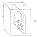
- An apparatus 1 for delivering fluid to a reaction site includes a substrate 10, such as a silicon wafer, mounted on a platform 12, which includes a rotary stepper motor (not shown), such as a Zeta 57-51-10 Motor and a Zeta 4 Rotary Driver manufactured by Parker Compumotor Company of Rohnert Park, California, U.S.A.
- the rotary stepper motor rotates substrate 10 in the directions of arrow A.
- a rail 14 is suspended above and transects, e.g. , bisects, substrate 10.
- a linear stepper motor 16 such as a L20 Stepper Motor, manufactured by Parker Compumotor Company of Rohnert Park, California, U.S.A., is mounted on rail 14, such that linear stepper motor 16 is movable in one dimension in the directions of arrow B along rail 14 over the surface of substrate 10.
- the rotary stepper motor is controllable to rotate substrate 10 at a plurality of variable and continuous speeds in either direction of arrow A.
- an AT6200 Controller manufactured by Parker Compumotor Company of Rohnert Park, California, U.S.A., may be used to control the operation of the rotary stepper motor.
- the rotary stepper motor may be operated to rotate substrate 10 continuously in a manner similar to that of the disk in a compact disc player, so that a centrifugal force is generated on substrate 10, or incrementally, so that substrate 10 may be moved a less than one revolution with respect to the position of linear stepper motor 16.
- Substrate 10, platform 12, rail 14, and linear stepper motor 16 may be enclosed within a container 18.
- Container 18 allows the atmosphere surrounding the reaction sites to be strictly monitored and controlled during testing.
- Container 18 may be airtight to prevent dust and moisture from settling on and effecting the operation of linear stepper motor 16 or the rotary stepper motor and to permit the maintenance of positive or negative pressure within container 18.
- dust and moisture may adversely effect the chemical or biochemical reactions, or both, occurring at the reaction sites and alter the outcomes of chemical and biochemical tests.
- container 18 may be equipped with a humidity and temperature sensor 19, so that the level of and changes in humidity and temperature may be detected.
- container 18 When low or high relative humidity or temperature, or both, is (are) detected, assaying operations may be terminated, or the atmospheric conditions within container 18 may be corrected. Changes in humidity or temperature, or both, may cause evaporation of all or a portion of the deposited fluid or dilution of the fluid with condensation.
- the container environment may be controlled by establishing a vacuum, increasing air pressure, regulating environmental temperature, or establishing a predetermined container atmosphere, such as a nitrogen atmosphere, an oxygen-rich atmosphere, a nobel gas (inert) atmosphere, or a combination thereof.
- container 18 also serves to reduce or eliminate air disturbances at or near the surface of substrate 10.
- Fig. 2A depicts a perspective view of a fluid dispenser 2, which may include linear stepper motor 16 and which may be mounted on rail 14.
- a fluid stream comprising a serialization of measured amounts of aliquot(s) and measured amounts of separating fluid(s) is delivered to fluid dispenser 2 through a fluid input/return tube 20.
- Fluid dispenser 2 includes a dispenser platform 15 that is suspended below linear stepper motor 16 by four dispenser platform supports 17.
- Components relating to the aligning of a dispenser outlet 21 over a reaction site on substrate 10 also may be mounted and stabilized on platform 15.
- the length of fluid dispenser outlet 21 is minimized in order to reduce or eliminate dead space.
- fluid input/return tube 20 From fluid input/return tube 20, the fluid is received by a fluid input tube 20' and delivered to fluid dispenser outlet 21. Fluid, which is not delivered to dispenser outlet 21, is returned to fluid input/return tube 20 through a fluid return tube 20". Further, fluid that is delivered to dispenser outlet 21, but which is not delivered to substrate 10 may be withdrawn through suction return tube 22.
- a suction device (not shown) draws undelivered fluid from dispenser outlet 21. The suction device creates a pressure differential across the orifice of suction return tube 22, such that the pressure in suction return tube 22 is less than the ambient pressure surrounding the dispenser outlet(s), e.g. , a vacuum sufficient to remove fluid exiting dispenser outlet 21.
- Linear stepper motor 16 receives movement signals from an external computer (not shown) through a computer connection (not shown).
- a timing device 23 e.g. , an electronic timing device, may measure flow rate and determine the amount of fluid delivered from dispenser outlet 21 by means of at least one flow sensor 25 positioned adjacent to dispenser outlet 21.
- flow sensors 25 may detect the interruption or diminution of an electromagnetic energy beam, e.g. , a laser or high intensity light beam, directed across the orifice of dispenser outlet 21.
- Flow sensors 25 may be connected to timing device 23 by a timing connection line 24.
- timing device 23 may send signals over a timing signal return line 24' and a signal transfer line 120 to a computer (not shown) to activate and deactivate the suction device (not shown), and thereby control the amount of fluid delivered to substrate 10 through dispenser outlet 21.
- a fluid dispenser 2 may include a detection mechanism, e.g. , these components may comprise a multi-function head, to determine whether and to what extent a chemical reaction has occurred at a reaction site.
- a light source (not shown) may supply high intensity light to fluid dispenser 2 through a light source input 27 to a light input optical fiber 27'.
- Light input optical fiber 27' is fixed adjacent to dispenser outlet 21, so that high intensity light may be directed onto at least one reaction site of substrate 10. The amount and nature of the light reflected from the reaction site may indicate the occurrence and progress of the reaction.
- Such reflected light may be collected by a light receiving optical fiber 28, a receiving end of which also may be positioned adjacent to dispenser outlet 21.
- light from light input optical fiber 27' may stimulate fluorescence at the at least one reaction site, and such fluorescence may by detected by light receiving optical fiber 28.
- Light received by light receiving optical fiber 28 is conducted to a photomultiplier tube 29 that includes a band pass filter and generates an electrical signal describing the nature and amount of the light reflected from the at least one reaction site.
- a photomultiplier tube may also be a photo-diode array.
- Photo-diode arrays are known light detecting elements of a charge coupled device (CCD).
- a source of electromagnetic energy may be supplied to detection mechanism and directed onto at least one reaction site of substrate 10. Again, the amount and nature of the reflected electromagnetic energy may indicate the occurrence and progress of the reaction. This signal then is returned to a computer (not shown) for analysis over signal transfer line 120.
- At least one sensor may be mounted on fluid dispenser 2 in order to identify reaction sites or to aid in determining a start location for dispenser outlet 21 with respect to the surface of substrate 10, or both.
- the at least one sensor may receive a signal emanating from an emitter positioned on substrate 10 ( see Fig. 6C , described below), or the at least one sensor may transmit an interrogating signal to substrate 10, e.g. , to a transponder positioned adjacent to a reaction site or group of reaction sites, and then receive a locating signal in response.
- the at least one sensor may read, i.e., scan, at least one locating mark, e.g. , an indexing mark or a bar code, on the surface of substrate 10.
- Such a locating mark also may include a tracking mark to guide Fluid dispenser 2 to a reaction site. Bar codes, micro-scale bar codes, and bar code readers are known in the art.
- Figs. 2B and 2C depict two embodiments of a delivery mechanism 200 and 200', respectively, for controlling the delivery of fluids through a dispenser outlet to the reaction sites.
- delivery mechanism 200 includes a portion of fluid input tube 20' and a portion of fluid return tube 20" forming a U-shaped connection. Arrows F depict the flow path of the serialized fluid through the U-shaped connection.
- Dispenser outlet 21 extends substantially perpendicular to the fluid flow path as fluid passes from fluid input tube 20' into fluid return tube 20".
- a first electro-mechanical controller 202 such as a solenoid, controls a return side valve 204, and first controller 202 may receive control signals 206 from timing device 23.
- first controller 202 and return side valve 204 are positioned sufficiently distant from dispenser outlet 21, such that vibrations or movement, or both, caused by the operation of first controller 202 or return side valve 204, or both, do not effect the alignment of dispenser outlet 21 over at least one reaction site on substrate 10.
- Fluid may be supplied to fluid input tube 20' under a pressure differential determined relative to the ambient air pressure within container 18. Nevertheless, this pressure is sufficient to force the majority of the fluid in fluid input tube 20' to pass directly across dispenser outlet orifice 208 and into fluid return tube 20", and any fluid entering dispenser outlet 21 may been collected by the suction device (not shown) through suction return tube 22. However, when return side valve 204 is closed, fluid from fluid input tube 20' flows directly into dispenser outlet 21. Moreover, because dispenser outlet 21 may narrow toward a dispenser outlet tip 210, the flow velocity of fluid leaving dispenser outlet 21 may be greater than the flow velocity within fluid input tube 20'.
- dispenser outlet orifice 210 may have a diameter of less than about 10 ⁇ m and preferably, less than about 4 ⁇ m.
- a pressure differential in a range of about 0.01 to 2000 psi is created across dispenser outlet orifice 210, and preferably, a positive pressure in a range of about 50 to 500 psi. If a suction device is used to draw off portions of the flow of serialized fluid from dispenser outlet orifice 210, a similar, but inverse, pressure differential is created across the orifice of suction return tube 22 adjacent to dispenser outlet orifice 210.
- delivery mechanism 200' also includes a portion of fluid input tube 20' and a portion of fluid return tube 20" forming a U-shaped connection. Arrows F again depict the flow path of the serialized fluid through the U-shaped connection.
- Dispenser outlet 21 extends substantially perpendicular to the fluid flow path as fluid passes from fluid input tube 20' into fluid return tube 20".
- First controller 202 controls return side valve 204, and first solenoid 206 again may receive control signals 206 from timing device 23.
- a second electro-mechanical controller 212 such as a solenoid, controls an input side valve 214, and second controller 212 also may receive control signals 206 from timing device 23.
- delivery mechanism 200' includes a four-way connection 216 having dispenser outlet orifice 208 providing access to dispenser outlet 21 and a dispenser fluid pump orifice 218 providing access to dispenser fluids (not shown) provided by a dispenser fluid pump 220.
- the dispenser fluids may be the same as the separating fluid(s) in the serialized fluid.
- first and second controllers 202 and 212, return side valve 204, input side valve 214, dispenser fluid pump 220 are positioned sufficiently distant from dispenser outlet 21, such that vibrations or movement, or both, caused by the operation of any or all of these components does (do) not effect the alignment of dispenser outlet 21 over at least one reaction site on substrate 10.
- fluid may be supplied to fluid input tube 20' under a small pressure differential, e.g. , less than about 10 psi, and preferably less than about 2.5 psi, determined relative to the ambient pressure within container 18. Nevertheless, this pressure is sufficient to force the majority of the fluid in fluid input tube 20' to pass directly across dispenser outlet connection 208 and dispenser fluid pump connection 218 and into fluid return tube 20".
- a dispenser fluid such as a separating fluid is pumped into dispenser fluid pump orifice 218 by dispenser fluid pump 220
- dispenser fluid pump 220 fluid from fluid input tube 20' flows directly into dispenser outlet 21.
- dispenser outlet 21 may narrow toward dispenser outlet orifice 210, the flow velocity of fluid leaving dispenser outlet 21 may be greater than the flow velocity within fluid input tube 20'.
- delivery mechanisms 200 and 200' redirect the flow of fluid in fluid input tube 20' into dispenser outlet 21.
- control of the amount of fluid and the number and type of aliquot(s) supplied to the various reaction sites on substrate 10 may be accomplished by the control of return side valve 204.
- control of the amount of fluid and the number and type of aliquot(s) supplied to the various reaction sites on substrate 10 may be accomplished by the control of return side valve 204 and input side valve 214, as well as dispenser fluid pump 220.
- the suction device may be used to draw off fluid through suction return tube 22 and thereby, controlling the amount of fluid dispensed from dispenser outlet 21 that is delivered to substrate 10.
- Delivery mechanisms 200 and 200' may comprise of channels and micro-mechanical devices formed within a block of material, such as a plurality of layers of semiconductor material.
- a block of material such as a plurality of layers of semiconductor material.
- grooves or trenches may be etched into a block of semiconductor material and micro-mechanical devices, such as valves 204 and 214, may be formed integrally with the grooves or trenches.
- a second block of semiconductor material may be joined to the etched block to cover the grooves or trenches to form tube-like channels.
- the fluid dispenser may employ ink-jet technology to provide measured amounts of aliquot(s) to reaction sites on the substrate surface.
- a fluid dispenser may eject a micro-droplet stream of the at least one fluid from the dispenser outlet, and an electrostatic accelerator and deflector may direct the micro-droplet stream to at least one of the reaction sites.
- a fluid dispenser may include a micro-fluidic device employing an oscillating solenoid for pumping fluid from a capillary tube or a piezoelectric device having a piezoelectric tube to dispense measured aliquots separated by air from a capillary tube, or the like. Because the aliquots are separated by air, excessive dilution of the aliquots is avoided.
- Such devices may include the BioJet Quanti3000TM fluid dispenser, which is manufactured by BioDot, Inc. of Irvine, California, U.S.A.
- This device employs an inkdot-type fluid delivery system.
- This device may achieve flow rates up to 50 ⁇ l/sec. of a fluid having a viscosity in a range of I to 20 centipoise. This range of flow rates, however, may be extended dependent on fluid rheology.
- this device may deliver lines of fluid with volumes as low as 250 nl/cm. and line widths in a range of 0.25 to 5 mm. The specifications were determined by dispensing deionized water with 0.5% surfactant added.
- This device also may deliver droplets of fluid with volumes as low as 4 nl/droplet and droplet diameters in a range of 0.25 to 5 mm. Achievable droplet volumes and diameters are dependent upon fluid and fluid membrane characteristics.
- BioJet Quanti3000TM fluid dispenser may achieve a flow repeatability of less than 1% cumulative volume variations for delivered lines and of less than 5% variation between drops.
- the BioJet Quanti3000TM fluid dispenser carries a swept volume of less than 40 ⁇ l and is supplied by a feeding tube carrying 5 ⁇ l/cm.
- this fluid dispenser may be equipped with a filter the fluid reagents before delivery to a reaction site. Such a filter may provide for removal of particulates with a diameter of less than 10 microns.
- the fluid dispenser may be equipped with means for de-aerating the fluid flow. These devices may employ an oscillating solenoid, for example, a solenoid oscillating at a rate of about 100 Hz, for pumping fluid from a capillary tube or a piezoelectric tube that is excited by frequencies up to about 1000 Hz which surrounds a capillary tube, respectively.
- Such devices may achieve flow rates of less than about 10 to 500 ⁇ l/sec., and preferably, of less than about 200 ⁇ l/sec.
- the orifices of the capillary tubes of these devices may have a diameter in a range of about 50 to 175 ⁇ m.
- FIG. 3 depicts a perspective view of the apparatus relating to the present invention.
- An apparatus 3 for delivering fluid to a reaction site includes substrate 10, such as a silicon wafer, mounted on platform 12, which includes a first rotary stepper motor (not shown), such as a Zeta 57-51-10 Motor and a Zeta 4 Rotary Driver.
- the first rotary stepper motor rotates substrate 10 in the directions of arrow A.
- a second rotary stepper motor 30, such as a Zeta 57-51-10 Motor or a Zeta 4 Rotary Driver, is mounted on platform 12, and a pivot arm 32 is mounted on second rotary stepper motor 30.
- a fluid dispenser 34 is mounted on pivot arm 32, and pivot arm 32 is of sufficiently length, such that fluid dispenser 34 may be rotated through an arc in two dimensions by the rotation of second rotary stepper motor 30 in the directions of arrow B to reach the entire surface of rotating substrate 10
- the first rotary stepper motor is controllable to rotate substrate 10 at a variety of speeds in either direction of arrow A.
- an AT6200 Controller may be used to control the operation of the first rotary stepper motor.
- the first rotary stepper motor may be operated continuously, so that a centrifugal force is generated on substrate 10, or incrementally, so that substrate 10 may be moved less than one revolution and stopped at a new orientation with respect to the position of fluid dispenser 34.
- pivot arm 32 may be operated in a manner similar to that of a tracking arm of a hard disk magnetic computer memory.
- a first rotary stepper motor may rotate substrate 10, while fluid dispenser 34 is positioned over substrate 10 by the rotary motion of rotating second rotary stepper motor 30 to pivot arm 32.
- Substrate 10, platform 12, second stepper motor 30, pivot arm 32, and fluid dispenser 34 may be enclosed within container 18.
- Container 18 allows the atmosphere surrounding the reaction sites to be strictly monitored and controlled during testing.
- Container 18 may be airtight to prevent dust and moisture from settling on and effecting the operation of the rotary stepper motors and to permit the maintenance of positive or negative pressure within container 18. Moreover, dust and moisture may adversely effect the chemical and biochemical reactions occurring at the reaction sites and alter the outcomes of chemical and biochemical tests.
- container 18 may be equipped with a humidity and temperature sensor 19, so that levels of and changes in humidity and temperature may detected.
- container 18 When low or high relative humidity or temperature, or both, is (are) detected, assaying operations may be terminated or the atmospheric conditions within container 18 may be corrected Further, because of the importance of delivering precise amounts of fluid to small reaction sites, container 18 also serves to reduce or eliminate air disturbances at or near the surface of substrate 10.
- substrate 10 may be equipped with a plurality of calibrating holes 36. Such calibrating holes 36 may be employed in combination with or in place of the locating marks described above.
- substrate 10 may include four calibrating holes 36 positioned around the outer circumference of substrate 10 at 90° intervals.
- An electromagnetic energy sensor (not shown) may be aligned beneath each of calibrating holes 36, such that when an electromagnetic energy source (not shown), which may be mounted on fluid dispenser 34, is directly over one of calibrating holes 36 electromagnetic energy generated by the electromagnetic energy source is detected by the corresponding electromagnetic energy sensor. This combination of the electromagnetic energy source with corresponding electromagnetic energy sensors may be used to locate fluid dispenser 34 over substrate 10 and to calibrate the aligning means of fluid dispenser 34.
- each reaction site may be positioned a precise number of stepper motor "steps" from each other and from at least one of calibrating holes 36. Therefore, once fluid dispenser 34 locates and identifies one of calibrating holes 36, fluid dispenser 34 may be moved quickly and precisely between reaction sites and over the surface of substrate 10.
- Fig. 4A is a schematic view of another embodiment of the fluid dispenser.
- a chemical or biological sample or samples are drawn from a fluid serializer 40, which accesses an aliquot fluid source and a separating fluid source (not shown).
- a pump may alternately draw amounts of an aliquot fluid or fluids from an aliquot fluid source through an aliquot fluid conduit and amounts of a separating fluid, such as a solvent, oil, air, immiscible fluid, a noble gas, or the like, from a separating fluid source through a separating fluid conduit, so that a serialized fluid stream, i.e. , a fluid stream including alternating amounts of an aliquot or aliquots and amounts of separating fluid.
- serialized samples may be prepared as part of a serialized library, which are preformatted and stored for later use in the apparatus.
- a pressure control device 42 may create a vacuum within container 18, whereby amounts of aliquot fluid or fluids and amounts of separating fluid may be drawn into dispenser input tube 20'.
- a valve may be used to alternatively place dispenser input tube 20' in communication with a source or sources of aliquot fluid or fluids and a source of a separating fluid. The vacuum in container 18 then may cause amounts of aliquot fluid or fluids and separating fluid to be drawn into dispenser input tube 20'.
- amounts of aliquot fluid or fluids and amounts of separating fluid may be formed as droplets, and an open end of dispenser input tube 20' may be positioned to draw selected droplets into dispenser input tube 20'.
- Fig. 4B is an enlarged view of dispenser input tube 20' illustrating a serialized fluid stream including alternating amounts of one of two aliquot(s) and a separating fluid, such as an immiscible fluid or solvent
- a separating fluid such as an immiscible fluid or solvent
- a solvent may be chosen as a separating fluid, so that aliquot residue is removed by the solvent as the serialized fluid passes through dispenser input tube 20'.
- a timing device 23 includes a flow sensor 25 to determine the rate of flow of the serialized fluid, so that activating and deactivating signals may be sent to suction device 44 via a timing signal connection 46.
- the amounts of aliquot or separating fluid may include a component detectable by flow sensor 25.
- Fluid drawn from dispenser outlet 21 by suction device 44 is removed from the apparatus via suction return tube 22.
- the fluid dispenser outlet 21, as well as the fluid dispenser and the substrate may be enclosed within container 18.
- Pressure control device 42 may be used to maintain a positive or negative pressure within container 18.
- fluid 400 comprises a separating fluid 402, a first fluid aliquot 404, and a second fluid aliquot 406.
- Second fluid aliquot 406 includes a plurality of flow sensor components 408.
- components 408 may be magnetic beads, and such beads may be detected as they pass through fluid inlet tube 20' in close proximity to an coil or other magnetic sensor. If the diameter of fluid inlet tube 20', the order of serialization, and the amounts of aliquot and separating fluid are known, the flow rate of the serialized fluid stream may be determined.
- each amount of aliquot or separating fluid may be determined from a signal generated by flow sensor components 408 in flow sensor 24, e.g. , by varying the strength of the magnetic field generated by the magnetic beads or the density of the magnetic bead in an aliquot or a separating fluid, or both. Nevertheless, other types of sensor components may generate detectable signals such as fluorescence, radiation, electrical charge, or the like.
- each fluid aliquot may have a volume in the range of about 3 to 5 ⁇ l, and preferably, in a range of about 4 to 5 ⁇ l.
- timing device 23 may deactivate and reactivate suction device 44 or energize and de-energize first controller 202 or controllers 202 and 212 to deliver a measured amount of aliquot to a particular reaction site.
- a further enlargement of a portion of dispenser input tube 20' is shown.
- first fluid aliquot 404 is pumped through dispenser input tube 20', friction between first aliquot 404 and the walls of dispenser input tube 20' causes the outer leading and trailing edges of the aliquot to mix with the separating fluid 402 and to create mixing zones 414.
- delivered portions of first fluid aliquot 404 are drawn from within aliquot boundaries 416.
- Aliquot boundaries 416 identify the portion of the aliquot unaffected by frictional forces and by mixing with the separating fluid 402. The location of aliquot boundaries 416 depends in part on the pressure at which fluid 400 is pumped, the composition of first fluid aliquot 404, and the material of dispenser input tube 20'.
- a third embodiment of the apparatus 1' may include a multi- function head 4 including at least one fluid dispenser 50 for conveying at least one fluid form a fluid line 51 to at least one of the reaction sites and a readout device 5.
- Readout device 5 may include means for locating a reaction site, such as the means for reading a locating mark at a reaction site and for monitoring the chemical assays or biochemical reactions at the reaction sites.
- Each of such fluid dispensers 50' includes a fluid dispenser outlet (not shown).
- the fluidics and detection functions of the apparatus may be combined in a multi-function head 4.
- apparatus 1' includes a substrate 10 mounted on a rotary chuck 110 including a spindle 111.
- a rotary stepper motor (not shown) may rotate substrate 10 in either direction of arrow A'.
- a rail 14' is suspended above and transects, e.g. , bisects substrate 10.
- a linear stepper motor 16' is mounted on rail 14', such that linear stepper motor 16' is movable in one dimension in the directions of arrow B' along rail 14' over the surface of substrate 10.
- a multi-function head may be moved to a particular reaction site and stopped and held at that site until a reaction is complete or for a predetermined period of time, i.e. , a time sufficient to allow detection of assay results.
- Rail 14' is mounted on a supporting arm 13.
- Supporting arm 13 may be mounted on a positioning motor (not shown), such that multi-function head 4 may be raised or lowered with respect to substrate 10.
- Apparatus 1' may include substantially u-shaped platform 15' which may be suspended by four platform supports 17' from linear stepper motor 16'.
- a dispenser/readout support 115 is positioned within the open portion of u-shaped platform 15'.
- Fluid dispenser 50 including fluid supply line 51 and readouts device 5 including three optical fiber receptacles 52 and 54a and 54b and their associate optical fibers: read fiber 53 and tracking fibers 55a and 55b, are mounted on support 115.
- fluid dispenser 50 and readout device 5 are initially positioned through the interaction of the movement of substrate 10 by the rotary stepper motor (not shown) and the movement of u-shaped platform 15' by linear stepper motor 16', adjustments to the position of fluid dispenser 50 and readout device 5 may be made by a three-axis micropositioner 56.
- Dispenser/readout support 115 maybe mounted on three-axis micropositioner 56, which may in turn be mounted on u-shaped platform 15'.
- micropositioner 56 may move dispenser/readout support 115 along three-axes to adjust the position of the fluid dispenser outlet (not shown) and optical fiber 53 and 55a and 55b.
- the readout device 5 may be combined with a tracking system, such as in a (Compact Disc) CD pickup head, e.g. , Sony KSS361A Optical Pickup manufactured by Sony Corporation of Tokyo, Japan, or the readout device 5 may be physically separate from the tracking system.
- a tracking system such as in a (Compact Disc) CD pickup head, e.g. , Sony KSS361A Optical Pickup manufactured by Sony Corporation of Tokyo, Japan
- a tracking system such as in a (Compact Disc) CD pickup head, e.g. , Sony KSS361A Optical Pickup manufactured by Sony Corporation of Tokyo, Japan
- a tracking system such as in a (Compact Disc) CD pickup head, e.g. , Sony KSS361A Optical Pickup manufactured by Sony Corporation of Tokyo, Japan
- known optical pickup heads such as those found in CD players, light emitted from a laser is split into three beams, i.e. , a
- the central beam impinges upon the CD surface in order to read the binary coded information and to provide a feedback signal for focusing the central beam on the CD surface while the two flanking beams provide feedback signals for tracking the pickup head over the CD surface.
- the light reflected from the CD surface is received through the lens, is deflected by the turning mirror through the beam splitter, and impinges upon a photodiode array. Feedback signals then are generated by virtue of the geometry of the photodiode array.
- the operation of such feedback control systems is described in more detail in G. Thomas and W. Ophey, "Optical Recording," PHYSICS WORLD, 36-41 (Dec. 1990).
- the track pitch of a CD is about 1.6 microns and the width of the encoding pits on the CD surface is about 0.5 microns.
- the flanking beams described above may strike the surface of the CD surface at a separation of about 2.1 microns apart, i.e. , the CD track pitch plus the pit width. While a tracking system substantially similar to the CD tracking system described above may be suitable for the present invention, certain modifications may be necessary depending upon the precise configurations of the multi-function head and the substrate. In the present invention, for example, it may be necessary to alter the angle of separation of the flanking beams, so that they strike the CD surface at a wider or narrower separation to accommodate different sizes of reaction sites. This may be accomplished by altering or replacing the lens, as appropriate.
- the CD tracking system may employ a laser diode, which may emit primarily infrared light.
- the laser diode found in CD players typically emits a fraction of a milliwatt.
- the laser diode may be replaced with a fiber optic connector allowing a source of electromagnetic energy of a predetermined power and wavelength to be optically coupled to the apparatus.
- a diffraction grating (not shown) may be placed in the path of the reflected beams.
- a spectrometer may be created Such a spectrometer may be used to detect the progress or occurrence of a biological or chemical reaction at a reaction site.
- the optics and the laser input of the CD tracking system may be modified to enable it to act as an excitation source and as a means for monitoring and reading the assay results at the reaction site, in addition to tracking the reaction sites.
- the optics of the CD tracking system is altered to increase the separation between the three projected light beams, such that the two outer most beams straddle the well at a reaction site.
- the laser diode of the CD tracking system may then be replaced with a fiber optic connector to couple light in from any type of laser.
- the photodiodes in the photodiode array of the CD tracking system may be selectively replaced according to their sensitivity to wavelengths and low light levels that are expected to be received from the reaction sites. Alternatively, some or all of the photodiodes may be replaced with an appropriate photomultiplier tube.
- readout device 5 may comprise three optical fibers, such as three fifty (50) micron fibers, arranged in a triangular configuration in the multi-function head 4 As depicted in Fig. 5 , a first optical fiber receptacle 52 receives a first fiber 53 First optical fiber 53 may be split, e.g. , bifurcated, such that first fiber 53 may function to deliver laser light to the substrate surface and to receive reflected light from the substrate surface. Consequently, first optical fiber 53 enables the apparatus to detect chemical and biochemical changes at the reaction sites and to read any indexing marks.
- three optical fibers such as three fifty (50) micron fibers
- the laser or light source is selected based on the type of assay(s) to be performed and is coupled to first fiber 53 by an optical fiber launcher, such as a KT210 Optical Fiber Launcher, manufactured by Thor Labs, Inc, of Newton, New Jersey, U.S.A.
- first fiber 53 may be coupled to a photomultiplier tube (e.g. , a photodiode array) or a spectrometer.
- Second and third optical fiber receptacles 54a and 54b receive a second fiber 55a and 55b, respectively. These two fibers 55a and 55b trail first fiber 53 and may be coupled to individual photodiodes to receive reflected electromagnetic energy and generate tracking signals.
- a bottom view of readout device 5 is depicted.
- This figure shows the arrangement of readout fiber 53 and tracking fibers 55a and 55b, with respect to the fluid dispenser outlet 60.
- an anti-reflective coating is applied in specific geometric configurations at precise locations along the substrate, such as that depicted in Fig. 7 .
- Electromagnetic energy may be transmitted down the first or read fiber 53 and the second and third or tracking fibers 55a and 55b or down the read fiber exclusively.
- the modulation of the intensity of the reflected light by the anti-reflective coating may enable the indexing and tracking signals to be read.
- a locating mark 70 may comprise both a start bit 72, an indexing mark 74, a dispense/stop bit 76, and a tracking bit 78
- Start bit 72 instructs the readout device to begin reading the locating mark.
- Indexing mark 74 identifies the particular reaction site and may consist of one or more submarks, such as submarks 74a and 74b.
- Dispense/stop bit 76 may instruct multi-function head 4 to pause at theat position or to initiate the dispensing of an aliquot or aliquots for perform a chemical assay or to cause a biochemical reaction.
- Tracking mark 78 guides the dispenser outlet (not shown) over a reaction site 80. As may be seen from a comparison of Figs.
- multi-function head 4 if multi-function head 4 is properly centered over locating mark 70, tracking fibers 55a and 55b receive an equal amount of reflected electromagnetic energy from the substrate surface.
- shifts by multi-function head 4 or misalignment ofthe multi-function head 5 to the right or left may be detected, and these offsets may be corrected.
- fluid dispenser 50 and redout device 5 comprising first, second and third fiber receptacles 52, 54a and 54b, respectively, may be mounted together on u-shaped platform 15' movably affixed to a three-axis micropositioner 56.
- Micropositioner 56 may permit further adjustments, e.g.
- read fiber 53 may scan the indexing mark.
- Read fiber 53 also may function as a proximity sensor to correct for movement by the multi-function head 4 away from or toward the substrate. This may be accomplished by monitoring the light intensity of the reflected light in areas in which the anti-reflective coating is absent.
- the entire multi-function head and feedback positioning system may be mounted on a XYZ translation stage that has a range of motion significantly greater than that of the fine-feedback positioning system that is mounted to the XYZ translation stage.
- Feedback actuation may be used to make fine adjustments to the positioning of the fluid dispenser and the readout device and may be provided by a variety of means, such as piezoelectric blocks, voice coils, worm drives, and the like.
- the apparatus may be modified to provide for such fine adjustments by the addition of a second three-axis micropositioner between the first micropositioner and the dispenser/readout support. This second micropositioner has a smaller range of movement and a higher degree of accuracy than the first micropositioner, e.g. , a range of adjustment of less than about 100 microns and an accuracy of about 0.1 micron.
- the shield structure also may comprise a cap formed over the geometric cavity of each reaction site.
- Such caps may include an opening sufficiently large to allow a stream of fluid to be directed therethrough, but sufficiently small, so as to retain the fluid within the cavity and reduce or eliminate evaporation of the fluid from the cavity.
- streams containing nanoliter volumes of reagents, cleaning fluids, buffers, and the like may be directed through the cap opening.
- a large volume droplet e.g. , a droplet having a volume in a range of about 0.1 to 0.5 ⁇ l, is then dispensed onto the cap opening. If the droplet has sufficient surface tension and is dispensed at a low velocity, it will seal the cap opening without entering the cavity.
- This sealing droplet may acts as a removable cover that may be removed by centrifugal force caused by the rotation of the substrate.
- the sealing droplet may be electrically gated.
- the wetting capabilities of the droplet may be altered to increase or decrease its adherence to the cap.
- electronic components may be placed in the cavity to control the electrical gating of the covering drops.
- a reaction site 80 is depicted as a geometric cut or etched cavity formed in the surface of substrate 10.
- Reaction sites 80 may be formed by chemical etching or ion etching, or the like.
- the shape of reaction site 80 may depend in part on the crystalline structure of substrate 10.
- the reaction site depicted in Figs. 8A and 8B is shown to have a simple rectangular shape, it has a locating mark 82 and is equipped with a shield structure 84.
- Shield structure 84 aids in the reduction of evaporation losses from reaction site 80, the retention of fluid within reaction site 80, and the prevention fluid from covering locating mark 82.
- Surface micromachining, especially on semiconductor materials, is known in the art.
- Substrate 10 may include at least about 20,000 reaction sites, and preferably, at least about 100,000 reaction sites.
- a radial pattern comprising substantially square wells with edges with a length of about 110 microns may be formed in an oxide layer grown on a silicon wafer.
- a photo resist such as a Microposit 1810 photoresist, manufactured by Shipley Company, Marlborough, Massachusetts, U.S.A., may be spun onto the oxide layer on the surface of the silicon wafer.
- the photo resist may then be exposed through a mask to produce the appropriate pattern, and then developed and allowed to dry.
- the water then maybe placed in a hydrofluoric acid bath to remove the exposed oxide layer, and the wafer may be placed in a potassium oxide bath to etch the uncovered silicon.
- Acetone may be used to remove the residual photo resist, and a second hydrofluoric acid bath may be used to remove the remaining oxide. This procedure produces anisotropically etched wells with the geometric shape of an inverted pyramid.
- Solid support substrates may be formed within reaction sites 80. These structures provide a point at which biochemical probes may be affixed to the reaction sites 80.
- the probes may be used to bind particular targets such as polymers, e.g. , polynucleotides, DNA, RNA, PNA, and antibodies, or antibody fragments or mixtures thereof
- the probes may bind targets such as individual nucleotides and nucleosides, such as adenosine, guanosine, cytosine, thymidine, uracil, or combinations thereof, and molecular structures such as enzymes proteins, plasmids, chromosomes and chromatids, and cellular structures, such as mitochondria, ribosomes, and the like.
- microorganisms such as prokaryotic or eukaryotic cells, including mammalian cells, bacteria, yeast and protozoa, viruses, phages, and combinations thereof, may be bound to the probes
- These structures may be formed by photolithographic techniques or materials may be incorporated into substrate 10 to form the solid support structures.
- suitable materials which may provide points for direct probe attachment may include electrometal materials, such as gold, niobium oxide, iridium oxide, platinum, titanium, zinc, and other metals.
- Solid support substrates and probes may be used to ensure that particular targets are retained in particular reaction sites for testing. The use of such structures and probes is described in U.S Patent No. 5,532,128 to Eggers et al .
- Locating marks 82 are discussed in detail with respect to Fig. 7 and may serve several functions. First, they allow the apparatus to determine its starting position. Second, they allow the apparatus to accurately deliver fluid to a predetermined reaction site by simply scanning the locating marks until the desired site is found. Third, although the precision achievable with the stepper motors may enable the apparatus to track its movements across the surface of substrate 10 by a form of dead-reckoning, the apparatus may detect positioning errors by comparing the apparatus's position by dead-reckoning to that of a known calibration point or reaction site. Fourth, because positioning errors may be determined, the apparatus may re-calibrate itself by comparing its calculated position to its known position with respect to the calibration points or reaction sites of substrate 10.
- a perspective view of substrate 10 having a spindle 90 is depicted.
- Spindle 90 may support substrate 10 and permit the rotary stepper motor to engage substrate 10. Further, spindle 90 may permit electric connections between electronic and electromechanical elements, e.g. , microelectromechanical systems, positioned on substrate 10 and power and control sources separate from substrate 10.
- Figs. 9B-9D depict overhead views of solid angle sectors of substrate 10 exemplary of embodiments of substrate 10.
- a solid angle sector 92 which includes a plurality of reaction sites 80 aligned radially from spindle 60.
- Each of reaction sites 80 has locating mark 82, which is depicted as comprising two bars.
- the use of this identifying mark is intended to be merely exemplary, and other identifying marks, such as indexing marks, bar codes, number codes, color codes, or the like, may also be employed. Further, an identifying mark may consist of a combination of characters or markings, or both, and the position of the mark with respect to the center of substrate 10 or with respect to spindle 90.
- a solid angle sector 92' which includes a plurality of circular reaction sites 80' and electronic or electro-mechanical elements 93, which are integral with, adjacent to, or connected to reaction sites 80'.
- electronic elements include transponders for receiving and responding to an interrogation signal; heating coils for raising the temperature at a reaction site, temperature sensors to measure or monitor temperature or temperature changes at a reaction site; electric field generating elements for altering the electro-magnetic field at a reaction site, e.g.
- a serpentine resistor may be used to heat proteins until denatured.
- chemically sensitive gates and ion sensitive gates are transistors whose gates have been replaced with by an ion selective permeable membrane. Chemically and ion sensitive gates may be used to detect changes in pH as well as changes in chemical and ion composition.
- substrate 10 may include interdigitated arrays (IDAs).
- IDA interdigitated arrays
- An IDA may comprise two arrays of rectangular electrodes that are placed so that the arrays intermesh, but do not contact each other. Chemical reactions occurring between the arrays and generating electrical charges causes a resultant current to flow in the arrays. The resultant current flow may be monitored to indirectly monitor the progress of chemical reactions at the reaction site.
- Electromechanical elements 93 may produce a vibration at the reaction site to stir or mix a plurality of substances to facilitate or accelerate chemical or biochemical interactions.
- substrate 10 may include elements, e.g. , electrodes, that actively alter the electrostatic charge on substrate 10 in local areas. Such an electrostatic charge may attract or repel microvolumes of fluid. Consequently, such electrodes may be used to aid in delivering precise amounts of the at least one fluid to the at least one reaction site.
- an electrostatic field consisting of "hills” and “valleys” may be generated across the entire surface of substrate 10, thus, creating a plurality of "virtual" reaction sites.
- these electrostatic fields may be used to create vertical and horizontal containment fields. These virtual reaction sites may reduce cross-contamination between sites.
- the surface charge also may be manipulated by coating or depositing a material having a desired charge onto the surface of substrate 10. This technique may be used in conjunction with the elements described above.
- Reaction sites 80' may be joined to elements 93 by a reaction site connection 64.
- connections 64 may transfer information concerning the reaction site or may serve to transfer energy to alter the chemical or biochemical interactions at the reaction site, or both.
- elements 93 may be connected to each other, e.g. , interconnected, by axial connections 95 or by radial connections 96, or by a combination of these connections.
- elements 93 may be interconnected radially through spindle 90, whereby signals may be transmitted to elements 93 from a computer (not shown) or other signal source and data from the reaction sites may be sent for storage and analysis to a computer or other data storage and analysis device or displayed on a monitor or printer or the like.
- elements may be interconnected via a device for combining two or more signals, i.e. , a multiplexer (not shown).
- a multiplexer for example, by using a plurality of multiplexers with between about 10 to 100 connections per multiplexer, all of the reaction sites on the substrate may be interconnected.
- a solid angle sector 92" which includes a plurality of circular reaction sites 80', a dispersion point 97, and a plurality of substantially radial channels 98, which channels 98 join dispersion point 97 to reaction sites 80'.
- dispenser outlet 21 may be aligned by rotary stepper motor 12 and linear stepper motor 16 with dispersion point 67. An amount of fluid then may be delivered to dispersion point 97.
- the rotary stepper motor may be used to rotate substrate 10 at sufficient speed to create a centrifugal force to draw a portion of the fluid from dispersion point 97 through channels 98 to reaction sites 80'.
- Fig. 9D depicts an embodiment using channels 98 and the centrifugal force generated by the rotation of substrate 10. However, it is not necessary to use such channels to transfer fluids to various reaction sites. If sufficient fluid is placed in a dispersion point 97 or in a plurality of dispersion points 97, the centrifugal force created by a rotating substrate 10 transfers a fluid across the entire surface of substrate 10 and to all reaction sites 80' . The amount of fluid required depends upon the size of the substrate, the number of reaction sites, the amount of fluid required at each reaction site, and the placement of the dispersion point or dispersion points.
- Fig. 10 depicts an overhead view of a pair of reactions sites, i.e. , reaction sites 80, joined by a channel 100 and a microfluidic device 102, such as a microfluidic pump or valve.
- Staged chemical and biochemical testing may be accomplished by providing a fluid or fluids to a reaction site for a first stage of testing and then the product or products of such first stage testing may be transferred by means of devices 102 through channels 100 to another reaction site or sites for subsequent testing stages.
- Channels 100 may be formed or etched or otherwise cut into the surface of substrate 10.
- channels 100 may be formed as tubes or conduits passing beneath the surface of substrate 10 to permit multi-level transfers of fluids or the products of chemical and biochemical reactions between reaction sites.
- the aliquots would be delivered to a dispenser outlet via a dispenser input tube.
- Aliquots and separating fluids i.e. , an immiscible fluid or a solvent, would pass through the dispenser input tube as a serialized fluid. Air gaps would be formed between each aliquots and each amount of separating fluid.
- the serialized fluid then would be delivered to the dispenser outlet at a pressure differential relative to the ambient pressure within container 18, e.g. , a positive pressure in a range of about 0.01 to 2000 psi, and preferably, a positive pressure in a range of less than about 500 psi, such that the air gaps do not compress significantly.
- the movement of the aliquots may be monitored using a photo-diode and a photo-transmitter, which sense the change in the refractive index as the air gaps pass the sensor.
- the time between sensing and dispensing would be calculated based on the speed of the fluid flow.
- the fluid flow may be dispensed continuously.
- a suction return tube would be positioned at the dispenser outlet, such that the suction return tube draws away the separating fluid portion of the fluid flow and leading and trailing portions of the aliquot. See Fig. 4C.
- the portion of fluid that is not drawn away, would be timed to flow straight from the dispenser outlet onto the surface of a silicon wafer.
- the suction device which is connected to suction return tube, would be a high-vacuum system that is controlled via high-power solenoids located at a sufficient distance from the dispenser outlet, so that the forces do not cause shaking of the dispenser outlet in the vicinity of the silicon substrate.
- a continuous stream of fluid may be applied to cover everything, reaction sites and non-reaction sites, or individual aliquots may be delivered to individual reaction sites.
- reaction results may be read. This would be accomplished by using a fiber optic tube that mounted adjacent to the dispenser outlet. The entire substrate surface then would be exposed to ultra-violet light. Reaction sites in which a blocking reaction occurred would show no fluorescence due to a fluorophor carried in the aliquot(s), e.g. , conjugated with proteins contained in an aliquot. Other reaction sites would emit fluorescence. Preferably, however, the inverse situation would be employed, in which a researcher would determine the occurrence of a reaction by the presence, rather than absence, of the fluorescence.
- An identifying mark e.g. , indexing marks and bar codes, may be placed adjacent to each reaction site, whereby a identifying mark reader would detect and read the mark by changes in its reflectance.
- Either ultra-violet or non-ultraviolet light may be used to determine the occurrence of a reaction, as well as to determine or verify the identity of a reaction site.
- reaction sites may be located via dead-reckoning However, a dead-reckoning system would require periodic calibration.
- a feedback system such as one utilizing identifying marks, may be used to confirm the accuracy of and, if necessary, re-calibrate a dead-reckoning system.
- Rhodamine solution a green He-Ne laser, lasing at about 543.5 nm, was used to transmit light along a first portion of a bifurcated optical fiber, e.g. , optical fiber 53.
- the common end of this bifurcated fiber was oriented orthogonally to a silicon wafer (the substrate) mounted on a rotary chuck, such as rotary chuck 110 depicted in Fig. 5 .
- the bifurcated optical fiber allows about 53 microwatts of laser light to impinge upon droplets of Rhodamine solution dispensed by a BioJet Quanti3000TM fluid dispenser.
- the portion of the laser light reflected from the substrate surface is gathered via the common end of the bifurcated fiber and transmitted along a second portion of the bifurcated optical fiber.
- the signal received by the second portion of the fiber is passed through a high pass filter in order to remove noise and feedback associated with the laser, at a cutoff wavelength of about 565 nm
- This filtered signal was then transmitted to a photomultiplier tube, (PMT) e.g. , a Hamamatsu PMT, Model No. 5784-01, manufactured by Hamamatsu Corporation, ofBridgewater, New Jersey, U.S.A., for analysis.
- PMT photomultiplier tube
- the purpose of this first test is (1) to determine whether the readout devices of the type intended for use in embodiments of this apparatus could actually detect the small volumes of a Rhodamine solution dispensed from the fluid dispensers suitable for use in the embodiments discussed above and (2) to determine the signal peak and the signal-to-noise ratio (SNR).
- the test involved the steps of: dispensing a droplet of Rhodamine solution having a volume of about 10.4 nl onto a silicon wafer and stepping the readout device across the droplet at a rate of about I mm/sec, while sampling the output of the PMT at a sampling rate of about 1000 Hz.
- the 10.4 nl droplet is clearly detectable.
- a peak output of about 3.5 V with a noise level of about 250 mV were measured.
- a SNR of about 14:1 was calculated using available fluid dispensing and readout devices.
- a significant portion of the signal noise could have been eliminated by using a bandpass filter centered on a wavelength of about 580 nm, i.e. , the emission peak of the Rhodamine solution, instead of a highpass filter. Additionally, because the light exiting the fiber was not collimated, further signal degradation was experienced.
- the approximate diameter of the droplet on the silicon wafer is determinable from the sampling data to be about 650 microns. However, a 10.4 nl sphere of fluid is calculated to have diameter of about 270 microns.
- Surface energy interactions between the droplet and the silicon wafer may cause the droplet of Rhodamine solution to spread out and coat the surface. Such spreading occurred in part because the droplets were placed on a flat surface of the silicon wafer, rather than into an etched well. As a result, the effective path length of light within the sample decreased, which weakened the resulting signal.
- appropriate geometry, i.e. , wells, and appropriate surface coatings it seems likely that the path length could be increased by at least a factor or two.
- the purpose of this second test was to create an intensity/thickness profile of a 10.4 nl droplet, to confirm the lower bounds of the dynamic range available for sensing, using available readout devices, and to determine source of hysteresis in the intensity signal.
- the test involved the steps of: dispensing a droplet of Rhodamine solution having a volume of about 10.4 nl onto a silicon wafer and stepping the readout device forwards and backwards across the droplet at a rate of about 0.5 mm/sec, while sampling the output of the PMT at a sampling rate of about 500 Hz.
- the intensity plot of a droplet is primarily a function of two variables: the excitation path length, which is essentially the thickness of the drop, and the focusing effect created as light of the passes through the droplet. Because the tested droplets were relatively flat, the majority of the modulation of the intensity signal was primarily attributable to the thickness modulation across the droplet, rather than to any focusing effects. Consequently, the forward scan data depicted in Fig. 12A indicates that the excitation path length of the droplet (which is proportional to the thickness of the droplet) is greatest in the center of the droplet and least at the periphery of the droplet. This result was as expected.
- the left edge of the intensity profile indicated that a measurable signal was generated across a distance of about 85 microns. However, the right edge of the profile indicated that across a similar distance, the signal generated was about 1.5 times that of the left edge. This difference indicated that smaller areas of the droplet may be resolved if the path length were increased.
- the reverse scan intensity curve indicated that the source of hysteresis was the droplet itself
- the reverse intensity profile was a mirror image of the forward intensity profile. This suggested that the droplet sitting on the silicon wafer was "pushed" slightly to the right.
- the cause of this offset may be due to the fluid dynamics of the fluid dispenser, electrostatic effects, or a combination thereof.
- the about one half-volt of signal lost on the reverse intensity curve was due to the evaporation of the droplet during testing.
- the purpose of this third test was to show open loop accuracy of the feedback stepper motors and to make a rough quantitative assessment of minimum detectable volume.
- the test involved the steps of dispensing a single droplet with a volume of about 10.4 nl in a known location and moving the readout device by dead-reckoning to the droplet, and monitoring the output of the PMT at a sampling rate of about 1000 Hz, until the droplet evaporated
- the accuracy of the operation and control of the stepper motor is evidenced by the intensity plot.
- the peak value of about 3.25 volts is similar to the peak values obtained in Test 1 when scanning a droplet. This indicates that the stepper motor and motor controls arc capable of positioning a multi-function head substantially at the center of a droplet.
- the three-axes micropositioner may be used to make adjustments, e.g. , adjustments in a range of less than about 15 mm with an accuracy of about one micron, in any of three Cartesian axes to the position of the multi-function head, once the head has been positioned substantially over a reaction site.
- the intensity signal will decrease thereby tracking the loss of droplet volume.
- the volume of the droplet decreases due to evaporation, the intensity signal will decrease thereby tracking the loss of droplet volume.
- the volume of the droplet decreases due to evaporation, the intensity signal will decrease thereby tracking the loss of droplet volume.
- a volt signal may be correlated to a volume of about 3 nl. Consequently, a volume of about 3 nl may be a lower limit for the detection of a droplet using the equipment configuration of this test.
- configurations may permit detection of still smaller volumes.
- These configurations may include modifications to the readout device's transmission and analysis of the interrogating light transmission, such as increasing the path length of the laser detection beam, using a bandpass filter to reduce or eliminate noise, collimating the light exiting the first portion of the bifurcated optical fiber, increasing the power of the excitation source, e.g. , the laser, and combinations thereof.
- the structure of the substrate may be modified to improve detection capabilities, such as forming wells that are geometrically designed to reflect light back into the second portion of the bifurcated optical fiber, incorporating photodiodes at the base of each well, and the like.
- detection capabilities may be improved by systemic changes such as the reduction of coupling losses throughout the apparatus.
- the purpose of this fourth test was to demonstrate that a binary code could be successfully placed on the substrate and read by the readout device.
- the test involved the steps of: depositing a 3-bit code that included a start and a stop bit on a silicon wafer at an annulus and subsequently, stepping the rotary stepper motor, such that the circumference of the annulus to be scanned passes under the bifurcated optical fiber.
- the resulting intensity signal was sampled at 1000 Hz.
- the binary code was formed from 0.1 microliter droplets of Rhodamine solution with the presence of a droplet indicating a one and the absence of a droplet indicating a zero. Each of the start and stop bits were indicated with a single droplet.
- the 3-bit code was successfully laid down and read back.
- the variation in pulse amplitude and duration were primarily due to evaporation of the droplets over the duration of the readout procedure.
- bits read later in the readout procedure generated lower signal intensity magnitudes. This indicates that a significant amount of evaporation occurred during the test. Nevertheless, the bit code remained readable even at the reduced droplet volumes.
- a general purposed computer 150 such as a computer comprising a Pentium® II microprocessor, manufactured by Intel Corporation of Santa Clara, California, U.S.A., or the like, capable of operating at at least about 300 MHz.
- computer 150 is preferably equipped with suitable software to create a coding environment fro accessing peripheral components.
- suitable software includes LabVIEW®software, Part No. 776670-03, and the LabVIEW® PID Control Toolkit software, Part No. 7766634-11, which are commercially available from National Instruments, Inc., of Austin Texas, U.S.A.
- Computer 150 is linked to a motor controller 151, e.g. , an AT6200 Controller, manufactured by Parker Compumotor Company of Rohnert Park, California, U.S.A.
- Motor controller 151 relays instructions from computer 150 to a linear stepper motor 152a, e.g. , a L20 Stepper Motor, manufactured by Parker Compumotor Company of Rohnert Park, California, U.S.A., and a rotary stepper motor 152b, e.g. , a Zeta 57-51-10 Motor and a Zeta 4 Rotary Driver manufactured by Parker Compumotor Company of Rohnert Park, California, U.S.A., via motor control 151.
- a linear stepper motor 152a e.g. , a L20 Stepper Motor, manufactured by Parker Compumotor Company of Rohnert Park, California, U.S.A.
- a rotary stepper motor 152b e.g. , a Zeta 57-51-10 Motor and a Ze
- computer 150 may be linked to a multi-function control 153, e.g. , a DAQ Board Model No. AT-MIO-16DE, manufactured by National Instruments, Inc., of Austin, Texas, U.S.A.
- a micropositioner 155 e.g. , a Low-Profile Three-Axis Micropositioner, Part No. CR 4000, manufactured by the Daedal Division of Parker Compumotor Company of Rohnert Park, California, U.S.A., may be operated directly to make positioning adjustments in a range of less than about 15mm with an accuracy of about one micron, along cartesian axes in the position of a fluid dispenser outlet and a readout device.
- Multi-function control 153 provides operating instructions received from computer 150 to at least a fluid dispenser 154, e.g. , a BioJet Quanti3000TM fluid dispenser, manufactured by BioDot, Inc. of Irvin, California, U.S.A.,and a laser 156.
- Laser 156 delivers a beam of light to the surface of a substrate 10, via a first bandpass filter 157.
- Laser 156 and first bandpass filter 157 are selected according to the assay to be accomplished.
- light reflected from the substrate's surface then may pass through a second bandpass filter 158 to a photomultiplier tube 159, e.g. , a Hamamatsu PMT, Model No. 5784-01, manufactured by Hamamatsu Corporation, of Bridgewater, New Jersey, U.S.A.
- fluid dispenser 154, micropositioner 155, and the readout device are combined on a multi-function head.
- Light from laser 156 is transmitted to the readout device over a fiber optic cable and from the end of the fiber optic cable is projected onto the surface of substrate 10.
- a suitable fiber optic cable for transmitting the light from laser 156 is a bifurcated cable, e.g. , Bifurcated 50 ⁇ m Fiber Optic Cable, Part No. BIF50 UV/VIS, manufactured by Ocean Optics, Inc. of Dunedin, Florida, U.S.A.
- a bifurcated cable e.g. , Bifurcated 50 ⁇ m Fiber Optic Cable, Part No. BIF50 UV/VIS, manufactured by Ocean Optics, Inc. of Dunedin, Florida, U.S.A.
- Such a cable allows a single cable to deliver laser light to the surface of substrate 10 and return it to photomultiplier tube 159.
- tracking fibers may be used to help align and guide the multi-function head to the reaction site.
- Such tracking fibers may be designed only to receive reflected light from the surface of substrate 10 which was generated by laser 156 and supplied by the bifurcated cable described above.
- the tracking fibers may also comprise bifurcated fiber optic cables and may provide their own light for tracking purposes.
- the light supplied to the tracking fibers may be generated by laser 156 or by a separate laser or lasers.
- each of the tracking fibers may comprise bifurcated cables and may supply light generated by laser 156 to the surface of substrate 10.
- the light transmitted by each fiber may pass through a separate bandpass filter, so that the light delivered by each tracking fiber is distinguishable over the light delivered by the other tracking fiber and over that delivered by the read fiber.
- the reflected light gathered by the tracking fibers may also be filter again before it is returned to a photomultiplier or photo-diode array for analysis.
Landscapes
- Chemical & Material Sciences (AREA)
- Biochemistry (AREA)
- Physics & Mathematics (AREA)
- Health & Medical Sciences (AREA)
- Life Sciences & Earth Sciences (AREA)
- Analytical Chemistry (AREA)
- General Health & Medical Sciences (AREA)
- General Physics & Mathematics (AREA)
- Immunology (AREA)
- Pathology (AREA)
- Chemical Kinetics & Catalysis (AREA)
- Organic Chemistry (AREA)
- Automatic Analysis And Handling Materials Therefor (AREA)
- Apparatus Associated With Microorganisms And Enzymes (AREA)
Abstract
Claims (50)
- Appareil destiné à effectuer une pluralité de dosages, comprenant :un substrat axialement rotatif comprenant une pluralité de sites de réaction non interconnectés, agencés de manière concentrique ;un moyen destiné à mettre en rotation et à réguler la rotation dudit substrat ;une tête multifonction comprenant un distributeur de fluide adapté pour transporter un fluide vers lesdits sites de réaction, un orifice de sortie du distributeur de fluide, et un dispositif de lecture ;un moyen destiné à identifier au moins l'un desdits sites de réaction ; etun moyen destiné à aligner ladite tête multifonction de telle sorte que ledit orifice de sortie du distributeur de fluide puisse être aligné avec au moins l'un desdits sites de réaction.
- Appareil selon la revendication 1, dans lequel ledit moyen pour mettre en rotation est adapté pour mettre en rotation et arrêter ledit substrat à une vitesse ajustable et régule la rotation dudit substrat en ajustant ladite vitesse, l'accélération et un sens de rotation.
- Appareil selon la revendication 1, dans lequel ledit moyen pour mettre en rotation est régulable pour mettre en rotation ledit substrat à des vitesses qui créent une force centrifuge afin d'enlever une partie dudit fluide dudit fluide de réaction.
- Appareil selon la revendication 1, dans lequel ladite tête multifonction comprend un distributeur de fluide monté de manière amovible sur un rail, ledit rail étant orienté sensiblement parallèle à une surface dudit substrat, et dans lequel ledit moyen pour alignement comprend un moteur pas à pas linéaire destiné à positionner ledit distributeur de fluide le long dudit rail de telle sorte que ledit orifice de sortie du distributeur de fluide est dirigé vers ledit substrat mis en rotation.
- Appareil selon la revendication 4, dans lequel ledit rail coupe transversalement ledit substrat.
- Appareil selon la revendication 4, dans lequel ledit moyen pour mise en rotation comprend un moteur pas à pas rotatif.
- Appareil selon la revendication 4, dans lequel ladite tête multifonction est montée sur ledit moteur pas à pas linéaire.
- Appareil selon la revendication 4, dans lequel ledit moyen pour identification comprend un capteur monté sur ladite tête multifonction.
- Appareil selon la revendication 8, dans lequel ledit capteur reçoit un signal émanant dudit substrat.
- Appareil selon la revendication 8, dans lequel ledit capteur transmet un signal d'interrogation et reçoit un signal d'emplacement.
- Appareil selon la revendication 8, dans lequel ledit capteur reçoit une marque d'emplacement sur ladite surface du substrat.
- Appareil selon la revendication 8, dans lequel ledit capteur lit une marque de suivi sur la surface dudit substrat.
- Appareil selon la revendication 4, dans lequel ledit moyen pour alignement comprend un ordinateur comportant une mémoire pour stocker un emplacement de départ sur la surface, dudit substrat pour ladite tête multifonction et ledit ordinateur fournit des signaux de mouvement audit moteur pas à pas rotatif et au moteur pas à pas linéaire, moyennant quoi lesdits moteurs alignent ladite tête multifonction pour permettre audit distributeur de fluide d'être sensiblement aligné sur au moins l'un desdits sites de réaction.
- Appareil selon la revendication 1, dans lequel ladite tête multifonction comprend un mécanisme de détection de réaction chimique comprenant une source d'énergie électromagnétique et un récepteur d'énergie électromagnétique, moyennant quoi l'énergie électromagnétique est dirigée dans un premier site de réaction de ladite pluralité de sites de réaction par ladite source d'énergie électromagnétique générée dans ledit premier cycle de réaction est reçue et analysée pour détecter une réaction chimique ou les produits de celle-ci par ledit récepteur.
- Appareil selon la revendication 14, dans lequel ladite source d'énergie électromagnétique comprend une fibre optique couplée à une source de lumière, moyennant quoi la lumière générée par ladite source de lumière est dirigée dans ledit au moins un site de réaction, et dans lequel ledit récepteur d'énergie électromagnétique comprend une fibre optique couplée de manière fonctionnelle à un photomultiplicateur ayant un filtre passe-bande, moyennant quoi un signal électrique est généré et transmis à un ordinateur pour détecter ladite réaction chimique.
- Appareil selon la revendication 1, dans lequel ladite tête multifonction comprend un mécanisme de détection de réaction chimique comprenant une réception d'énergie électromagnétique, moyennant quoi l'émission électromagnétique provoquée par les réactions chimiques ou biologiques dans au moins l'un desdits sites de réaction sont canalisées vers un détecteur d'énergie électromagnétique à des fins de détection.
- Appareil selon la revendication 1, dans lequel au moins l'un desdits sites de réaction est une cavité géométrique formée dans ledit substrat.
- Appareil selon la revendication 13, dans lequel au moins l'un desdits sites de réaction est une cavité géométrique formée dans ledit substrat, ladite cavité géométrique comportant une pluralité de surfaces qui sont orientées pour permettre à ladite énergie électromagnétique de se réfléchir à l'intérieur de ladite cavité pour augmenter une longueur de chemin d'énergie électromagnétique.
- Appareil selon la revendication 18, dans lequel des barrières réfléchissantes sont formées sur une périphérie de ladite cavité pour empêcher une interférence électromagnétique à partir d'une cavité adjacente.
- Appareil selon la revendication 1, dans lequel ledit substrat est constitué d'un matériau choisi dans le groupe constitué du verre, des céramiques, des matériaux semi-conducteurs, des matières plastiques, des composites et de leurs combinaisons.
- Appareil selon la revendication 1, dans lequel ledit substrat comprend des structures de support solide formées à l'intérieur desdits sites de réaction qui forment une pluralité de points au niveau desquels des sondes se fixent auxdits sites de réaction.
- Appareil selon la revendication 21, dans lequel lesdites structures sont formées d'un matériau électrométallique.
- Appareil selon la revendication 1, dans lequel ledit fluide comprend des quantités discrètes d'un aliquot de fluide et d'un fluide de séparation, et ledit distributeur comprend une pompe, un dispositif d'aspiration adapté pour tirer un courant à partir dudit distributeur et un dispositif temporisateur pour réguler ledit dispositif d'aspiration, dans lequel ladite pompe tire de manière alternée une première quantité discrète dudit aliquot de fluide et une seconde quantité discrète dudit fluide de séparation dans un tube distributeur et délivre un fluide mis en série dudit aliquot de fluide et ledit fluide de séparation vers ledit distributeur sous pression régulée.
- Appareil selon la revendication 23, dans lequel ledit dispositif temporisateur mesure un débit dudit courant à travers ledit tube distributeur et désactive et réactive ultérieurement ledit dispositif d'aspiration pour permettre à une partie de ladite première quantité discrète dudit aliquot de fluide d'être délivrée vers au moins un desdits sites de réaction.
- Appareil selon la revendication 23, dans lequel ladite première quantité discrète dudit aliquot de fluide est sensiblement identique à ladite seconde quantité discrète dudit fluide de séparation, dans lequel ledit aliquot de fluide comprend une première composante de capteur d'écoulement, et dans lequel ledit dispositif temporisateur comprend un capteur d'écoulement destiné à détecter ladite composante de capteur d'écoulement à mesure que ladite composante de capteur d'écoulement passe par ledit capteur.
- Appareil selon la revendication 25, dans lequel ladite composante de capteur d'écoulement est une pluralité de têtes magnétiques et ledit capteur d'écoulement est un capteur magnétique
- Appareil selon la revendication 1, dans lequel ledit fluide comprend une quantité discrète d'un aliquot de fluide et d'un fluide de séparation et ledit distributeur de fluide comprend une pompe, un mécanisme de soupape, un dispositif d'aspiration et un dispositif de temporisation, dans lequel ladite pompe tire une première quantité discrète dudit aliquot de fluide et une seconde quantité discrète dudit fluide de séparation dans un tube distributeur pour délivrer un fluide mis en série dudit aliquot de fluide et ledit fluide de séparation vers ledit distributeur sous pression régulée,
une première partie dudit fluide mis en série est distribuée à partir dudit distributeur vers au moins l'un desdits sites de réaction
ledit dispositif d'aspiration enlève une partie non désirée de ladite première partie dudit fluide mis en série, et
ledit dispositif temporisateur régule ledit mécanisme de soupape et ledit dispositif d'aspiration. - Appareil selon la revendication 27, dans lequel ledit distributeur s'étend sensiblement perpendiculairement à une direction d'écoulement de fluide à l'intérieur dudit tube distributeur et ledit mécanisme de soupape comprend une unité de régulation et une soupape régulée par ladite unité de régulation, ladite soupape étant positionnée en aval dudit distributeur et ladite unité de régulation étant régulée par ledit dispositif temporisateur, de telle sorte que lorsque la soupape est fermée, ledit fluide s'écoule vers ledit orifice de sortie du distributeur.
- Appareil selon la revendication 1, comprenant, en outre, un mécanisme de soupape comprenant une unité de régulation et une soupape régulée par ladite unité de régulation, ladite soupape destinée à réguler l'écoulement de fluide provenant dudit distributeur, dans lequel ledit distributeur s'étend sensiblement perpendiculairement à une direction d'écoulement de fluide à l'intérieur dudit tube distributeur, et dans lequel ladite soupape est positionnée en aval dudit distributeur et ladite unité de régulation est régulée par un dispositif temporisateur, de telle sorte que lorsque ladite soupape est fermée, ledit fluide s'écoule vers ledit orifice de sortie du distributeur.
- Appareil selon la revendication 29, dans lequel ledit dispositif temporisateur mesure un débit dudit écoulement de fluide à travers ledit tube distributeur.
- Appareil selon la revendication 29, dans lequel ledit mécanisme de soupape comprend une soupape à quatre voies dans ledit tube distributeur ;
une première unité de régulation et une première soupape régulée par ladite première unité de régulation, ladite première soupape étant positionnée en aval de ladite soupape à quatre voies ;
une seconde unité de régulation et une seconde soupape régulée par ladite seconde unité de régulation, ladite seconde soupape étant positionnée en amont de ladite soupape à quatre voies, et dans lequel
ledit distributeur s'étend d'un premier orifice de ladite soupape à quatre voies de telle sorte que lorsque ladite première soupape et ladite unité de régulation sont régulées par ledit dispositif temporisateur et lorsque lesdites première et seconde soupapes sont fermées, un fluide distributeur est pompé à travers ladite soupape à quatre voies et force ledit fluide vers ledit orifice de sortie du distributeur. - Appareil selon la revendication 1, dans lequel ledit distributeur de fluide éjecte un courant en micro-gouttelettes dudit fluide à partir dudit distributeur et un accélérateur électrostatique et un déflecteur dirigent ledit courant de micro-gouttelettes vers au moins l'un desdits sites de réaction.
- Appareil selon la revendication 1, dans lequel ledit moyen pour identification comprend une source de lumière et un détecteur de fluorescence et dans lequel une pluralité dudit aliquot de fluide est délivrée auxdits sites de réaction, et dans lequel ledit fluide comprend un fluorophor, moyennant quoi la fluorescence se produit dans au moins un desdits sites de réaction.
- Appareil selon la revendication 1, dans lequel ledit substrat comprend une pluralité de couches d'un matériau semi-conducteur, et dans lequel un élément électronique est formé sur ledit matériau semi-conducteur et joint à l'un desdits sites de réaction.
- Appareil selon la revendication 34, dans lequel ledit au moins un élément électronique est choisi dans le groupe constitué par les répondeurs, bobines chauffantes, capteurs de température, éléments de génération de champs électriques, éléments photosensibles, éléments photorésistants, éléments dénaturants, des grilles chimiquement sensibles, des grilles sensibles aux ions, des rangées internumérisées et leurs combinaisons.
- Appareil selon la revendication 34, dans lequel ledit élément électronique comprend une pluralité d'éléments électroniques interconnectés.
- Appareil selon la revendication 36, comprenant, en outre, un pivot autour duquel ledit substrat tourne et dans lequel une paire desdits éléments électroniques sont radialement interconnectés à travers ledit pivot.
- Appareil selon la revendication 36, dans lequel ladite paire d'éléments électroniques sont axialement interconnectés.
- Appareil selon la revendication 36, comprenant, en outre, un multiplexeur destiné à interconnecter lesdits éléments électroniques.
- Appareil selon la revendication 1, comprenant, en outre, un élément électromécanique qui est formé sur ledit substrat adjacent à au moins l'un desdits sites de réaction.
- Appareil selon la revendication 40, dans lequel ledit élément électromécanique produit une vibration pour agiter ledit fluide à l'intérieur d'au moins l'un desdits sites de réaction.
- Appareil selon la revendication 1, dans lequel ledit moyen pour mise en rotation comprend un premier moteur pas à pas rotatif, et dans lequel ledit orifice de sortie du distributeur est monté sur un bras pivot et ledit bras pivot est monté sur un moteur pas à pas secondaire, de telle sorte que ledit orifice de sortie du distributeur est régulable en pivotement sur ledit substrat rotatif.
- Appareil selon la revendication 1, dans lequel ledit substrat et ledit distributeur de fluide sont fermés dans un conteneur étanche à l'air.
- Appareil selon la revendication 1, dans lequel au moins l'un desdits sites de réaction comprend une cavité géométrique formée dans ledit substrat, ladite cavité géométrique comportant une structure d'écran pour empêcher une perte de fluide à partir dudit site de réaction.
- Appareil selon la revendication 44, comprenant, en outre, un dispositif de régulation de pression destiné à réguler la pression atmosphérique à l'intérieur dudit conteneur.
- Appareil destiné à effectuer une pluralité de dosage comprenant :un substrat axialement rotatif comprenant une pluralité de sites de réaction non interconnectés agencés de manière concentrique ;un moyen pour mettre en rotation ledit substrat ;une tête multifonction comprenant un distributeur de fluide adapté pour transporter un fluide vers chacun desdits sites de réaction, un orifice de sortie de distributeur de fluide, et un dispositif de lecture ;un moyen destiné à identifier au moins un desdits sites de réaction ; etun moyen destiné à aligner ladite tête multifonction de telle sorte que lorsque ledit orifice de sortie du distributeur de fluide est sensiblement aligné avec au moins l'un desdits sites de réaction, dans lequel ledit moyen pour mise en rotation est régulable pour mettre en rotation ledit substrat à une vitesse pour permettre à une partie dudit fluide d'être enlevable à partir de l'un desdits sites de réaction par une force centrifuge générée par la rotation dudit substrat.
- Appareil selon la revendication 1, dans lequel ladite tête multifonctionnelle comprend une pluralité de distributeur de fluide.
- Appareil selon la revendication 46, dans lequel ladite tête multifonctionnelle comprend une pluralité de distributeurs de fluide.
- Appareil selon la revendication 1, dans lequel ledit distributeur de fluide est adapté pour transporter une quantité inférieure à environ 0,5 µL dudit fluide à chacun desdits sites de réaction.
- Appareil selon la revendication 46, dans lequel ledit distributeur de fluide est adapté pour transporter une quantité inférieure
Applications Claiming Priority (3)
| Application Number | Priority Date | Filing Date | Title |
|---|---|---|---|
| US5579297P | 1997-08-15 | 1997-08-15 | |
| US55792P | 1997-08-15 | ||
| PCT/US1998/016958 WO1999009394A1 (fr) | 1997-08-15 | 1998-08-14 | Dispositif permettant de realiser des dosages au niveau de sites reactionnels |
Publications (2)
| Publication Number | Publication Date |
|---|---|
| EP1004015A1 EP1004015A1 (fr) | 2000-05-31 |
| EP1004015B1 true EP1004015B1 (fr) | 2004-01-02 |
Family
ID=22000189
Family Applications (1)
| Application Number | Title | Priority Date | Filing Date |
|---|---|---|---|
| EP98942073A Expired - Lifetime EP1004015B1 (fr) | 1997-08-15 | 1998-08-14 | Dispositif permettant de realiser des dosages au niveau de sites reactionnels |
Country Status (6)
| Country | Link |
|---|---|
| US (1) | US6338820B1 (fr) |
| EP (1) | EP1004015B1 (fr) |
| AU (1) | AU9020698A (fr) |
| CA (1) | CA2301095A1 (fr) |
| DE (1) | DE69820877T2 (fr) |
| WO (1) | WO1999009394A1 (fr) |
Families Citing this family (82)
| Publication number | Priority date | Publication date | Assignee | Title |
|---|---|---|---|---|
| US7060431B2 (en) | 1998-06-24 | 2006-06-13 | Illumina, Inc. | Method of making and decoding of array sensors with microspheres |
| US6846460B1 (en) | 1999-01-29 | 2005-01-25 | Illumina, Inc. | Apparatus and method for separation of liquid phases of different density and for fluorous phase organic syntheses |
| JP3984748B2 (ja) * | 1999-03-17 | 2007-10-03 | 株式会社日立製作所 | 化学分析装置と化学分析システム |
| ATE272213T1 (de) * | 1999-06-18 | 2004-08-15 | Gamera Bioscience Corp | Vorrichtungen und verfahren zur durchführung miniaturisierter homogener tests |
| DK1239952T3 (da) * | 1999-12-13 | 2012-01-02 | Illumina Inc | Syntetiseringsindretning til oligonukleotider ved anvendelse af en centrifugalkraft |
| US7390459B2 (en) | 1999-12-13 | 2008-06-24 | Illumina, Inc. | Oligonucleotide synthesizer |
| WO2001077640A2 (fr) | 2000-04-05 | 2001-10-18 | Alexion Pharmaceuticals, Inc. | Procedes et dispositifs de stockage et de distribution de liquides |
| US7420659B1 (en) * | 2000-06-02 | 2008-09-02 | Honeywell Interantional Inc. | Flow control system of a cartridge |
| CA2412275C (fr) | 2000-06-28 | 2009-12-08 | 3M Innovative Properties Company | Dispositifs, systemes et procede ameliores de traitement d'echantillons |
| US6720187B2 (en) | 2000-06-28 | 2004-04-13 | 3M Innovative Properties Company | Multi-format sample processing devices |
| US6734401B2 (en) | 2000-06-28 | 2004-05-11 | 3M Innovative Properties Company | Enhanced sample processing devices, systems and methods |
| US6627159B1 (en) | 2000-06-28 | 2003-09-30 | 3M Innovative Properties Company | Centrifugal filling of sample processing devices |
| WO2002014556A2 (fr) * | 2000-08-14 | 2002-02-21 | Van Andel Research Institute | Appareil d'impression de microreseaux rotatif multiplexe et procede de production de microreseaux |
| US20030064872A1 (en) * | 2001-07-20 | 2003-04-03 | Worthington Mark Oscar | Optical analysis disc and related drive assembly for performing interactive centrifugation |
| SE0104077D0 (sv) * | 2001-10-21 | 2001-12-05 | Gyros Ab | A method and instrumentation for micro dispensation of droplets |
| SE0103109D0 (sv) * | 2001-09-17 | 2001-09-17 | Gyros Microlabs Ab | Detector arrangement with rotary drive in an instrument for analysis of microscale liquid sample volumes |
| US20030054563A1 (en) * | 2001-09-17 | 2003-03-20 | Gyros Ab | Detector arrangement for microfluidic devices |
| US6889468B2 (en) | 2001-12-28 | 2005-05-10 | 3M Innovative Properties Company | Modular systems and methods for using sample processing devices |
| US7221783B2 (en) | 2001-12-31 | 2007-05-22 | Gyros Patent Ab | Method and arrangement for reducing noise |
| WO2003064998A2 (fr) * | 2002-01-31 | 2003-08-07 | Burstein Technologies, Inc. | Procede de declenchement par le biais de rainures de disque, et systeme et disques d'analyse optique associes |
| JP4194787B2 (ja) * | 2002-03-14 | 2008-12-10 | パナソニック株式会社 | 分析装置とそれに使用する分析用ディスク |
| WO2003082730A1 (fr) * | 2002-03-31 | 2003-10-09 | Gyros Ab | Dispositifs microfluidiques efficaces |
| US8150510B2 (en) * | 2002-04-15 | 2012-04-03 | Imperception, Inc. | Shock timing technology |
| US8383342B2 (en) | 2002-04-24 | 2013-02-26 | The University Of North Carolina At Greensboro | Compositions, products, methods and systems to monitor water and other ecosystems |
| US8048623B1 (en) | 2002-04-24 | 2011-11-01 | The University Of North Carolina At Greensboro | Compositions, products, methods and systems to monitor water and other ecosystems |
| US9126165B1 (en) | 2002-04-24 | 2015-09-08 | The University Of North Carolina At Greensboro | Nucleic acid arrays to monitor water and other ecosystems |
| US7361509B2 (en) * | 2002-04-29 | 2008-04-22 | Ortho-Clinical Diagnostics | Dynamic metered fluid volume determination method and related apparatus |
| TWI221523B (en) * | 2002-05-21 | 2004-10-01 | Sony Corp | Bioassay method, bioassay device, and bioassay substrate |
| EP1509760A1 (fr) * | 2002-05-31 | 2005-03-02 | Gyros AB | Agencement detecteur utilisant une resonance plasmonique de surface |
| US20050106714A1 (en) * | 2002-06-05 | 2005-05-19 | Zarur Andrey J. | Rotatable reactor systems and methods |
| JP4148705B2 (ja) * | 2002-06-19 | 2008-09-10 | 松下電器産業株式会社 | 分析装置 |
| US20040018635A1 (en) * | 2002-07-26 | 2004-01-29 | Peck Bill J. | Fabricating arrays with drop velocity control |
| JP2004093415A (ja) * | 2002-08-30 | 2004-03-25 | Sony Corp | バイオアッセイ用基板と基板情報読み取り装置及び基板情報読み取り方法 |
| US20040115830A1 (en) * | 2002-09-25 | 2004-06-17 | Igor Touzov | Components for nano-scale Reactor |
| US7053439B2 (en) * | 2002-10-29 | 2006-05-30 | Edwin Kan | Chemoreceptive semiconductor structure |
| WO2004042359A2 (fr) * | 2002-11-04 | 2004-05-21 | Transform Pharmaceuticals, Inc. | Analyse et optimisation de preformulation |
| US20040175822A1 (en) * | 2002-12-18 | 2004-09-09 | West Virginia University Research Corporation | Apparatus and method for edman degradation using a microfluidic system |
| US7332129B2 (en) | 2003-01-09 | 2008-02-19 | 3M Innovative Properties Company | Sample processing device having process chambers with bypass slots |
| CA2513985C (fr) | 2003-01-21 | 2012-05-29 | Illumina Inc. | Moniteur de reactions chimiques |
| US20040166551A1 (en) * | 2003-02-24 | 2004-08-26 | John Moulds | Detection of agglutination of assays |
| US20040241872A1 (en) * | 2003-03-17 | 2004-12-02 | Qiagen Operon, Inc. | Optical detection liquid handling robot system |
| US20040191127A1 (en) | 2003-03-31 | 2004-09-30 | Avinoam Kornblit | Method and apparatus for controlling the movement of a liquid on a nanostructured or microstructured surface |
| EP1620205A2 (fr) * | 2003-04-04 | 2006-02-01 | Tecan Trading AG | Outils en elastomere destines a fabriquer des dispositifs polymeres et utilisations de ceux-ci |
| US7517494B2 (en) * | 2003-04-30 | 2009-04-14 | Hewlett-Packard Development Company, L.P. | Test tray and test system for determining response of a biological sample |
| US7632675B2 (en) | 2003-06-05 | 2009-12-15 | Bioprocessors Corp. | Apparatus and method for manipulating substrates |
| WO2004113871A2 (fr) * | 2003-06-19 | 2004-12-29 | Nagaoka & Co., Ltd. | Circuits fluidiques pour preparation d'echantillons comprenant des disques biologiques et procedes correspondants |
| CN103454191B (zh) * | 2003-07-02 | 2016-01-06 | 泰尔茂比司特公司 | 用于利用预测数据分析算法控制血液处理离心机的方法 |
| KR100647282B1 (ko) | 2003-12-24 | 2006-11-17 | 삼성전자주식회사 | DNA 마이크로어레이 스폿팅(Spoting) 장치 및이를 이용한 스폿팅 방법 |
| FR2872575A1 (fr) * | 2004-07-01 | 2006-01-06 | Commissariat Energie Atomique | Procede et dispositif d'analyse de petits volumes de liquide |
| FR2872574B1 (fr) * | 2004-07-01 | 2006-11-17 | Commissariat Energie Atomique | Systeme de detection synchrone de fluorescence en goutte |
| WO2006006591A1 (fr) * | 2004-07-12 | 2006-01-19 | Arkray, Inc. | Analyseur, méthode pour spécifier la …réaction dans l’analyseur, appareil analytique |
| US7618589B2 (en) * | 2004-09-07 | 2009-11-17 | Hitachi Koki Co., Ltd. | Automatic dispenser |
| US7608446B2 (en) * | 2004-09-30 | 2009-10-27 | Alcatel-Lucent Usa Inc. | Nanostructured surface for microparticle analysis and manipulation |
| SE0402731D0 (sv) * | 2004-11-10 | 2004-11-10 | Gyros Ab | Liquid detection and confidence determination |
| US7754474B2 (en) | 2005-07-05 | 2010-07-13 | 3M Innovative Properties Company | Sample processing device compression systems and methods |
| USD564667S1 (en) | 2005-07-05 | 2008-03-18 | 3M Innovative Properties Company | Rotatable sample processing disk |
| US7763210B2 (en) | 2005-07-05 | 2010-07-27 | 3M Innovative Properties Company | Compliant microfluidic sample processing disks |
| US7323660B2 (en) | 2005-07-05 | 2008-01-29 | 3M Innovative Properties Company | Modular sample processing apparatus kits and modules |
| EP2024730A4 (fr) * | 2006-05-09 | 2014-07-16 | Axela Inc | Analyseur automatisé a diffraction de lumière |
| JP4901333B2 (ja) * | 2006-06-30 | 2012-03-21 | ローム株式会社 | マイクロチップ検査装置 |
| WO2008046112A1 (fr) * | 2006-10-13 | 2008-04-17 | Eliseev Alexey V | Procédés et puces à adn compatibles avec de commandes optiques à double fonction |
| JP5519297B2 (ja) * | 2007-03-13 | 2014-06-11 | アドヴァンスト リキッド ロジック インコーポレイテッド | 吸光度検出を向上させるための液滴アクチュエータの装置、構成および方法 |
| KR101278154B1 (ko) * | 2007-04-16 | 2013-06-27 | 삼성전자주식회사 | 원심력 기반의 미세유동 장치, 이를 구비한 미세유동시스템 및, 상기 미세유동 장치의 홈 위치 결정 방법 |
| US7578177B2 (en) | 2007-05-18 | 2009-08-25 | Siemens Energy, Inc. | MEMS emissions sensor system for a turbine engine |
| WO2009085350A1 (fr) * | 2007-12-27 | 2009-07-09 | Caridianbct, Inc. | Appareil de traitement de sang avec déclencheur de chambre de capture de cellules contrôlé |
| US7951059B2 (en) * | 2008-09-18 | 2011-05-31 | Caridianbct, Inc. | Blood processing apparatus with optical reference control |
| EP2361376B1 (fr) * | 2008-12-22 | 2020-09-23 | Terumo BCT, Inc. | Appareil de traitement du sang équipé d'un régulateur de tension linéaire à commande numérique pour impulsions optiques |
| US8834792B2 (en) | 2009-11-13 | 2014-09-16 | 3M Innovative Properties Company | Systems for processing sample processing devices |
| EP2644216B1 (fr) | 2009-12-11 | 2016-04-06 | Terumo BCT, Inc. | Système pour la séparation du sang avec un orifice d'extraction blindé et un contrôle optique |
| GB2476474B (en) * | 2009-12-22 | 2012-03-28 | Biosurfit Sa | Surface plasmon resonance detection system |
| BR112013029181B1 (pt) | 2011-05-18 | 2020-11-03 | Focus Diagnostics, Inc. | método e sistema para o processamento de dispositivos de processamento de amostras |
| WO2012158988A1 (fr) | 2011-05-18 | 2012-11-22 | 3M Innovative Properties Company | Systèmes et procédés de distribution sur un dispositif de traitement d'échantillons |
| MX336625B (es) | 2011-05-18 | 2016-01-26 | 3M Innovative Properties Co | Sistemas y metodos para medicion volumetrica en dispositivo de procesamiento de muestra. |
| WO2014127122A1 (fr) | 2013-02-18 | 2014-08-21 | Terumo Bct, Inc. | Système de séparation du sang équipé d'une chambre comportant un clapet interne à gravité |
| CN105810217A (zh) * | 2014-12-29 | 2016-07-27 | 广明光电股份有限公司 | 生物碟片及其定位方法 |
| CN105170055A (zh) * | 2015-07-31 | 2015-12-23 | 张家港江苏科技大学产业技术研究院 | 一种生化反应柜 |
| CN106841266B (zh) * | 2017-01-06 | 2018-06-22 | 厦门大学 | 一种适用于核磁共振实时检测化学反应的装置和使用方法 |
| US10434510B2 (en) * | 2017-05-06 | 2019-10-08 | International Business Machines Corporation | Microfluidic probe with bypass and control channels |
| CN108321485B (zh) * | 2018-03-05 | 2021-03-16 | 华北电力大学(保定) | 一种微波谐振腔体及汽轮机末级湿度检测装置 |
| WO2020237195A1 (fr) | 2019-05-22 | 2020-11-26 | The Regents Of The University Of California | Radiosynthétiseur de microgouttelettes ultra-compact automatisé |
| DE102022201938A1 (de) * | 2022-02-24 | 2023-08-24 | Hahn-Schickard-Gesellschaft für angewandte Forschung e.V. | Flüssigkeitstransfer zwischen rotierenden Modulen |
| CN119746762B (zh) * | 2025-01-14 | 2025-10-10 | 西北大学 | 一种基于激光辐照的哑铃形纳米材料可控制备装置及方法 |
Family Cites Families (39)
| Publication number | Priority date | Publication date | Assignee | Title |
|---|---|---|---|---|
| US3679367A (en) | 1970-09-14 | 1972-07-25 | Technicon Instr | Apparatus for determining the pack volume of particulates in liquid mixtures |
| FR2409514A1 (fr) | 1977-11-17 | 1979-06-15 | Bretaudiere Jean Pierre | Perfectionnement aux appareils d'analyse par centrifugation |
| CH629034A5 (de) | 1978-03-31 | 1982-03-31 | Ibm | Vorrichtung zum herstellen mehrschichtiger halbleiterelemente mittels fluessigphasen-epitaxie. |
| US4381291A (en) | 1979-02-23 | 1983-04-26 | Ab Fortia | Measurement of free ligands |
| DE3044385A1 (de) | 1980-11-25 | 1982-06-24 | Boehringer Mannheim Gmbh, 6800 Mannheim | Verfahren zur durchfuehrung analytischer bestimmungen und hierfuer geeignetes rotoreinsatzelement |
| JPS5848836A (ja) * | 1981-09-18 | 1983-03-22 | Toa Medical Electronics Co Ltd | 光学式自動分析測定装置 |
| DE3314961A1 (de) | 1983-04-25 | 1984-10-25 | Boehringer Mannheim Gmbh, 6800 Mannheim | Analysegeraet zur photometrischen bestimmung eines parameters einer fluessigkeit |
| GB8317124D0 (en) | 1983-06-23 | 1983-07-27 | Ekins R P | Free ligand assay |
| US5171695A (en) | 1986-08-06 | 1992-12-15 | Multilyte Limited | Determination of analyte concentration using two labelling markers |
| US4940527A (en) | 1987-06-01 | 1990-07-10 | Abbott Laboratories | Two-part test cartridge for centrifuge |
| US5242803A (en) | 1987-07-17 | 1993-09-07 | Martin Marietta Energy Systems, Inc. | Rotor assembly and assay method |
| US5173262A (en) | 1987-07-17 | 1992-12-22 | Martin Marietta Energy Systems, Inc. | Rotor assembly and method for automatically processing liquids |
| ES2049254T3 (es) | 1987-08-27 | 1994-04-16 | Biotrack Inc | Aparato y procedimiento para la dilucion y mezcla de muestras liquidas. |
| US4999304A (en) | 1987-12-28 | 1991-03-12 | Miles Inc. | Dynamic braking centrifuge |
| US5252294A (en) | 1988-06-01 | 1993-10-12 | Messerschmitt-Bolkow-Blohm Gmbh | Micromechanical structure |
| US5160702A (en) | 1989-01-17 | 1992-11-03 | Molecular Devices Corporation | Analyzer with improved rotor structure |
| KR920700403A (ko) | 1989-03-07 | 1992-02-19 | 혼고오 므쯔미 | 액체시료의 분석장치와, 이 분석장치를 사용한 액체시료의 분석방법 |
| IL94212A0 (en) | 1989-07-24 | 1991-01-31 | Tri Tech Partners And Triton B | Automated analytical apparatus and method |
| US5449621A (en) * | 1989-07-31 | 1995-09-12 | Biotope, Inc. | Method for measuring specific binding assays |
| US5171533A (en) * | 1989-07-31 | 1992-12-15 | Fine Richard A | Biological assay cassette and method for making same |
| US5006749A (en) | 1989-10-03 | 1991-04-09 | Regents Of The University Of California | Method and apparatus for using ultrasonic energy for moving microminiature elements |
| JPH03245049A (ja) | 1990-02-22 | 1991-10-31 | Idemitsu Petrochem Co Ltd | 液体試料分析用ディスク |
| DE4123818C2 (de) | 1991-07-18 | 1994-05-19 | Berthold Lab Prof Dr | Vorrichtung zur Messung der Chemilumineszenz einer in einem Probengefäß befindlichen Probe |
| US5413732A (en) | 1991-08-19 | 1995-05-09 | Abaxis, Inc. | Reagent compositions for analytical testing |
| IL103674A0 (en) | 1991-11-19 | 1993-04-04 | Houston Advanced Res Center | Method and apparatus for molecule detection |
| AU4047493A (en) | 1992-04-02 | 1993-11-08 | Abaxis, Inc. | Analytical rotor with dye mixing chamber |
| JPH0610900A (ja) * | 1992-04-27 | 1994-01-21 | Canon Inc | 液体移動方法及び移動装置ならびにこれを利用した測定装置 |
| DE69319427T2 (de) | 1992-05-01 | 1998-12-10 | Univ Pennsylvania | Analyse bei messung des durchflusswiderstandes |
| US5304487A (en) | 1992-05-01 | 1994-04-19 | Trustees Of The University Of Pennsylvania | Fluid handling in mesoscale analytical devices |
| JPH06265447A (ja) | 1993-03-16 | 1994-09-22 | Hitachi Ltd | 微量反応装置およびこれを使用する微量成分測定装置 |
| US5368704A (en) | 1993-08-06 | 1994-11-29 | Teknekron Corporation | Micro-electrochemical valves and method |
| US5409665A (en) | 1993-09-01 | 1995-04-25 | Abaxis, Inc. | Simultaneous cuvette filling with means to isolate cuvettes |
| US5639428A (en) * | 1994-07-19 | 1997-06-17 | Becton Dickinson And Company | Method and apparatus for fully automated nucleic acid amplification, nucleic acid assay and immunoassay |
| US5627041A (en) * | 1994-09-02 | 1997-05-06 | Biometric Imaging, Inc. | Disposable cartridge for an assay of a biological sample |
| CA2146177C (fr) | 1995-04-03 | 2000-09-05 | Adrian P. Wade | Reseau d'analyse de flux intelligent |
| ATE291225T1 (de) | 1995-12-05 | 2005-04-15 | Gamera Bioscience Corp | Vorrichtung und verfahren zum bewegen von fluiden mittels zentrifugalbeschleunigung bei der automatischen laborbehandlung |
| JP3245049B2 (ja) | 1996-03-29 | 2002-01-07 | 太陽誘電株式会社 | フェライト材料及びフェライト |
| US5935785A (en) * | 1997-04-30 | 1999-08-10 | Motorola, Inc. | Binding assay methods |
| US6013513A (en) * | 1997-10-30 | 2000-01-11 | Motorola, Inc. | Molecular detection apparatus |
-
1998
- 1998-08-14 WO PCT/US1998/016958 patent/WO1999009394A1/fr not_active Ceased
- 1998-08-14 US US09/134,141 patent/US6338820B1/en not_active Expired - Fee Related
- 1998-08-14 AU AU90206/98A patent/AU9020698A/en not_active Abandoned
- 1998-08-14 EP EP98942073A patent/EP1004015B1/fr not_active Expired - Lifetime
- 1998-08-14 DE DE69820877T patent/DE69820877T2/de not_active Expired - Fee Related
- 1998-08-14 CA CA002301095A patent/CA2301095A1/fr not_active Abandoned
Also Published As
| Publication number | Publication date |
|---|---|
| DE69820877T2 (de) | 2005-03-03 |
| EP1004015A1 (fr) | 2000-05-31 |
| US6338820B1 (en) | 2002-01-15 |
| CA2301095A1 (fr) | 1999-02-25 |
| AU9020698A (en) | 1999-03-08 |
| WO1999009394A1 (fr) | 1999-02-25 |
| DE69820877D1 (de) | 2004-02-05 |
Similar Documents
| Publication | Publication Date | Title |
|---|---|---|
| US6338820B1 (en) | Apparatus for performing assays at reaction sites | |
| US8137640B2 (en) | Acoustically mediated fluid transfer methods and uses thereof | |
| US8273304B2 (en) | Analytical biochemistry system with robotically carried bioarray | |
| US6563584B1 (en) | Method and device for fluorescence measurement | |
| US20020164824A1 (en) | Method and apparatus based on bundled capillaries for high throughput screening | |
| US20020179849A1 (en) | Multiplexed fluorescent detection in microfluidic devices | |
| US20030080143A1 (en) | System and method for dispensing liquids | |
| EP1257354A2 (fr) | Techniques et dispositif de fabrication de jeux ordonnes de microechantillons | |
| EP1246698A2 (fr) | Systemes et procedes d'echantillonnage et d'analyse a rendement ultra eleve | |
| EP1019712A1 (fr) | Appareil et procede d'electrofluidite capillaire | |
| US20020025582A1 (en) | Methods and devices for storing and dispensing liquids | |
| WO2005081801A2 (fr) | Procedes et appareil de lecture de petits volumes d'echantillons | |
| WO2002078834A2 (fr) | Procede et dispositif reposant sur l'emploi de capillaires en faisceau pour criblage a fort debit | |
| AU2002306207B2 (en) | Apparatus for performing assays at reaction sites | |
| AU2002338339A1 (en) | System and method for dispensing liquids |
Legal Events
| Date | Code | Title | Description |
|---|---|---|---|
| PUAI | Public reference made under article 153(3) epc to a published international application that has entered the european phase |
Free format text: ORIGINAL CODE: 0009012 |
|
| 17P | Request for examination filed |
Effective date: 20000310 |
|
| AK | Designated contracting states |
Kind code of ref document: A1 Designated state(s): DE ES FR GB IT SE |
|
| 17Q | First examination report despatched |
Effective date: 20010427 |
|
| GRAH | Despatch of communication of intention to grant a patent |
Free format text: ORIGINAL CODE: EPIDOS IGRA |
|
| GRAS | Grant fee paid |
Free format text: ORIGINAL CODE: EPIDOSNIGR3 |
|
| GRAA | (expected) grant |
Free format text: ORIGINAL CODE: 0009210 |
|
| AK | Designated contracting states |
Kind code of ref document: B1 Designated state(s): DE ES FR GB IT SE |
|
| PG25 | Lapsed in a contracting state [announced via postgrant information from national office to epo] |
Ref country code: IT Free format text: LAPSE BECAUSE OF FAILURE TO SUBMIT A TRANSLATION OF THE DESCRIPTION OR TO PAY THE FEE WITHIN THE PRESCRIBED TIME-LIMIT;WARNING: LAPSES OF ITALIAN PATENTS WITH EFFECTIVE DATE BEFORE 2007 MAY HAVE OCCURRED AT ANY TIME BEFORE 2007. THE CORRECT EFFECTIVE DATE MAY BE DIFFERENT FROM THE ONE RECORDED. Effective date: 20040102 |
|
| REG | Reference to a national code |
Ref country code: GB Ref legal event code: FG4D |
|
| REF | Corresponds to: |
Ref document number: 69820877 Country of ref document: DE Date of ref document: 20040205 Kind code of ref document: P |
|
| PG25 | Lapsed in a contracting state [announced via postgrant information from national office to epo] |
Ref country code: SE Free format text: LAPSE BECAUSE OF FAILURE TO SUBMIT A TRANSLATION OF THE DESCRIPTION OR TO PAY THE FEE WITHIN THE PRESCRIBED TIME-LIMIT Effective date: 20040402 |
|
| PG25 | Lapsed in a contracting state [announced via postgrant information from national office to epo] |
Ref country code: ES Free format text: LAPSE BECAUSE OF FAILURE TO SUBMIT A TRANSLATION OF THE DESCRIPTION OR TO PAY THE FEE WITHIN THE PRESCRIBED TIME-LIMIT Effective date: 20040413 |
|
| RAP2 | Party data changed (patent owner data changed or rights of a patent transferred) |
Owner name: BIOPROCESSORS CORPORATION |
|
| REG | Reference to a national code |
Ref country code: GB Ref legal event code: 732E |
|
| REG | Reference to a national code |
Ref country code: FR Ref legal event code: TP |
|
| ET | Fr: translation filed | ||
| PLBE | No opposition filed within time limit |
Free format text: ORIGINAL CODE: 0009261 |
|
| STAA | Information on the status of an ep patent application or granted ep patent |
Free format text: STATUS: NO OPPOSITION FILED WITHIN TIME LIMIT |
|
| 26N | No opposition filed |
Effective date: 20041005 |
|
| PGFP | Annual fee paid to national office [announced via postgrant information from national office to epo] |
Ref country code: FR Payment date: 20080818 Year of fee payment: 11 |
|
| PGFP | Annual fee paid to national office [announced via postgrant information from national office to epo] |
Ref country code: GB Payment date: 20080827 Year of fee payment: 11 |
|
| PGFP | Annual fee paid to national office [announced via postgrant information from national office to epo] |
Ref country code: DE Payment date: 20080930 Year of fee payment: 11 |
|
| GBPC | Gb: european patent ceased through non-payment of renewal fee |
Effective date: 20090814 |
|
| REG | Reference to a national code |
Ref country code: FR Ref legal event code: ST Effective date: 20100430 |
|
| PG25 | Lapsed in a contracting state [announced via postgrant information from national office to epo] |
Ref country code: FR Free format text: LAPSE BECAUSE OF NON-PAYMENT OF DUE FEES Effective date: 20090831 Ref country code: DE Free format text: LAPSE BECAUSE OF NON-PAYMENT OF DUE FEES Effective date: 20100302 |
|
| PG25 | Lapsed in a contracting state [announced via postgrant information from national office to epo] |
Ref country code: GB Free format text: LAPSE BECAUSE OF NON-PAYMENT OF DUE FEES Effective date: 20090814 |