EP1004110B1 - Dispositif pour afficher des caracteres et des symboles alphanumeriques - Google Patents
Dispositif pour afficher des caracteres et des symboles alphanumeriques Download PDFInfo
- Publication number
- EP1004110B1 EP1004110B1 EP97928220A EP97928220A EP1004110B1 EP 1004110 B1 EP1004110 B1 EP 1004110B1 EP 97928220 A EP97928220 A EP 97928220A EP 97928220 A EP97928220 A EP 97928220A EP 1004110 B1 EP1004110 B1 EP 1004110B1
- Authority
- EP
- European Patent Office
- Prior art keywords
- light emitting
- emitting diodes
- support
- circuit board
- electric motor
- Prior art date
- Legal status (The legal status is an assumption and is not a legal conclusion. Google has not performed a legal analysis and makes no representation as to the accuracy of the status listed.)
- Expired - Lifetime
Links
Images



Classifications
-
- G—PHYSICS
- G09—EDUCATION; CRYPTOGRAPHY; DISPLAY; ADVERTISING; SEALS
- G09G—ARRANGEMENTS OR CIRCUITS FOR CONTROL OF INDICATING DEVICES USING STATIC MEANS TO PRESENT VARIABLE INFORMATION
- G09G3/00—Control arrangements or circuits, of interest only in connection with visual indicators other than cathode-ray tubes
- G09G3/001—Control arrangements or circuits, of interest only in connection with visual indicators other than cathode-ray tubes using specific devices not provided for in groups G09G3/02 - G09G3/36, e.g. using an intermediate record carrier such as a film slide; Projection systems; Display of non-alphanumerical information, solely or in combination with alphanumerical information, e.g. digital display on projected diapositive as background
-
- G—PHYSICS
- G09—EDUCATION; CRYPTOGRAPHY; DISPLAY; ADVERTISING; SEALS
- G09F—DISPLAYING; ADVERTISING; SIGNS; LABELS OR NAME-PLATES; SEALS
- G09F9/00—Indicating arrangements for variable information in which the information is built-up on a support by selection or combination of individual elements
- G09F9/30—Indicating arrangements for variable information in which the information is built-up on a support by selection or combination of individual elements in which the desired character or characters are formed by combining individual elements
- G09F9/33—Indicating arrangements for variable information in which the information is built-up on a support by selection or combination of individual elements in which the desired character or characters are formed by combining individual elements being semiconductor devices, e.g. diodes
Definitions
- the invention relates to a device for displaying alpha-numerical Signs and symbols according to the generic term of Protection claim 1.
- LED's light emitting diodes
- Such a device is, for example, in practice in Form of a spherical LED display known, in which in the Inside of the sphere, generally of the rotationally symmetrical housing, made of acrylic glass or the like translucent material one or more rows of light-emitting diodes arranged vertically are on an appropriately trained carrier.
- the Carrier rotates at high speeds using an electric motor from, for example, 2000 rpm to 3000 rpm, whereby the one or more preferably parallel to the axis of rotation of the Electric motor-aligned LED row (s) also rotates or turn.
- the LED's become a still picture for the viewer or a standing or in the manner of a ticker moving, readable character and / or image sequence on the housing surface projected from an angular range of more than 270 ° is recognizable.
- FIG. 1 Another display device of the generic type is in international patent application PCT / RO95 / 00013 published as WO-A-9611462.
- the Block diagram includes a sequence generator for generation the code sequences for the character and image sequences and a Synchronization circuit for detecting the angular position of the rotating LED carrier, from which the rotational speed of the LED carrier is determined and regulated.
- a first object of the invention is therefore a device of the type mentioned with an improved control to create the display device and the LED's.
- translucent balls used generally have a only relatively small opening for the installation of the display technology or display arrangement with LEDs. It is also used for stabilization a counterweight to the or during the rotational movement the LED rows. Due to this, the assembly bumps such devices for significant technical difficulties, that do not allow series production.
- a second object of the invention is therefore a device to improve the type mentioned in such a way that technically simple and series production is possible.
- the inventive measures according to claim 1 an exact measurement of the speed of rotation of the drive motor or the rotating LED arrangement, due to which the LED control with the speed of rotation of the LED arrangement is synchronized. Interfering external influences, such as incident light rays, by means of a suitable software for optoelectronic rotation speed measurement are largely filtered out.
- the one with the coupled extremely accurate detection of the rotational speed optimal synchronization of the LED control is clear for one readable and flicker-free character and / or image sequence indispensable.
- the device is for the purpose the data transmission for control and programming with a PC interface and / or an infrared interface fitted.
- the infrared interface enables input a desired character and / or image sequence using a Remote control.
- FIG. 1 is a first preferred embodiment of the Device according to the invention in section along the axis of symmetry 21 of the arrangement shown.
- a Electric motor 2 mounted for an engine speed of about Is designed from 2000 to 3000 rpm.
- an electric motor 2 can preferably a synchronous motor can be used.
- the circuit board 4 contains the complete electronic circuits for the Control of the device, in particular a control of the LEDs or LED groups 6 via regulated constant current sources, a non-volatile storage of the alpha-numeric characters and / or pictograms and a character generator for implementation the character and / or image sequence into the corresponding one LED control.
- the electronic circuit board 4 also serves as mechanical holder for a in a preferred manner perpendicular to the circuit board 4, i.e. roughly parallel to Axis of symmetry 21, arranged carrier 5.
- carrier 5 On the carrier 5 is at least one preferably vertical row from radially to externally directed LEDs or LED groups 6 attached.
- the LEDs 6 on the carrier 5 are colored light-emitting diodes which can be predetermined color order. Both LEDs can be used in constantly changing colors and LEDs from same color can be used. The choice of color essentially depends from the planned ad. Furthermore, the application of course not on the one used in this embodiment only one LED row of sixteen LED's 6 limited. The Depending on the application, the row can have more or fewer LEDs exhibit.
- the control on the circuit board 4 ensures accordingly a stored specification (program, computer program) for a predetermined lighting of the desired one LEDs 6.
- a stored specification program, computer program
- the font bold, italic, etc.
- the running speed of the character and / or image sequence fixed, and the user can only and / or select and enter image sequence.
- a flexible Programming tool can of course also do that Font, the running speed or other parameters of the Character and / or image sequence to be displayed freely selected by the user become.
- This picture Due to the high speed on the drive shaft 20 of the electric motor 2 of about 3000 rpm is for the viewer of the display device a "standing" picture with a frame rate generated by about 50 Hz.
- This picture can be according to the given and programmed memory content a standing or moving typeface from alpha-numeric characters or also be a picture. Combinations are of course also such Characters possible.
- the LED heads 6 can be beveled, the beveling preferably takes place in the vertical. You can also alternatively, SMD LEDs 6 can also be applied.
- a flexible (elastically flexible) spring steel rod 7 attached to the side of the circuit board opposite the LED carrier 5 4 .
- a weight 8 which is very advantageously on the spring steel rod 7 in the longitudinal direction can be moved and locked in any position. This is an optimal and the structural as well as the operating conditions adjusted weight balance possible.
- spring steel rod 7 is also a rod from another Material with comparable properties can be used. Further it is conceivable, a simple instead of the spring steel rod 7 or rod that can be folded down or decayed several times or to choose a telescopic rod, which is due to the centrifugal force automatically flips up to its operating length when rotating or extends.
- a bendable, foldable or telescopic Compensation element 7 instead of a rigid mechanical compensation body has the advantage of easier assembly, in particular when assembling the complete device in housing with small receiving opening, as shown below with the second Embodiment will be explained in more detail in Fig. 4.
- the electrical connections 9 of the electronic circuit board 4, in this embodiment two contacts Power supply and two contacts for data transmission by an implementation (not shown) by the Base 1 and the electric motor 2 to high-quality sliding contacts 24 fed to the rotating coupling piece 3.
- the sliding contacts 24 run on the entire circumference of the coupling piece 3 and are for example and preferably made of gold.
- the two contacts for power supply are via a supply cable 10 connected to the network, which is also the electric motor 2 supplies the necessary energy.
- the two contacts to Data transmission is with a PC interface 11 in the base 1 connected to the device.
- a computer 12 At this PC interface 11 is a computer 12 with a terminal that can be connected at the same time networked several display devices of the type described can be.
- a remote control 13 can be controlled.
- an infrared sensor 14 whose connections for simplicity to the PC contacts are laid for data transmission.
- the infrared sensor 14 can now be either fixed on the resting base or foot 1 or one Part of the base 1 as well as moving on a rotating Part, such as on the carrier 5 or the circuit board 4 be mounted.
- the frequency range of data transmission with remote control 13 is in principle not limited to the infrared range but through the use of commercially available remote controls on.
- remote control 13 in contrast to the computer 12 usually does not have a screen or other display elements
- To check the data entered works in the case of Data transmission with remote control 13 the display device with its LED's 6 itself as a display for checking data entry.
- the display device further includes a measuring device 15 for exact measurement of the rotation speed of the LED arrangement 6 about the axis of rotation 21.
- the measuring device 15, which is shown in FIG drawn out enlarged, consists of a optoelectronic sensor 16 and a reflector 17.
- the off Photosensor 16 constructed transmitter and receiver is on the bottom the rotating circuit board 4 attached.
- the Reflector 17 is at the same distance from the axis of rotation 21 Photosensor 16 opposite, for example on the engine block 2, fixed fixed.
- an active transmitter in the form of a stationary transmitter diode 22 is provided, while the receiver 23 spaced opposite on the rotating carrier 5 or on the underside of the rotating Circuit board 4 is attached.
- the position of the reflector 17 marks, for example Zero crossing of the rotation.
- the transmitter of the photosensor 16 emits continuously or at least with a very rapid pulse sequence, which is a much higher frequency than the rotation of the LED array 6 should have one facing down Beam of light 18a. Whenever there is a reflector 17 and photosensor 16 face, i.e. once per rotation of the assembly, the light beam 18a is reflected by the reflector 17, and the reflected light beam 18b is from the receiver of the photosensor 16 added.
- the arrangement of the photosensor 16 and the reflector 17 is not limited to the type described above, it just has to be guaranteed be that a component of the measuring device 15 one component rotating with the LED arrangement 6 and the other Component is attached stationary. Furthermore, the measuring device 15 be arranged so that as little distracting as possible External influences influence the measurement of the rotational speed can. For this purpose, the distance between Photosensor 16 and reflector 17 chosen as small as possible.
- this software also allows, with an otherwise regular pulse sequence, possibly one-off pulses to pass over. So it is pretended that the fancy too Pulse would be present, so that a constant Rotational speed is measured.
- the entire arrangement described above with components 2-9, 14-17 and 20 is usually packaged 19 mounted.
- the housing 19 is essentially a spherical, cylindrical or other rotationally symmetrical housing.
- the spherical body 19 consists of a translucent or transparent material, e.g. acrylic glass, plastic, Glass or the like.
- the preferred ball body 19 has a diameter of about 30 cm and has on the other hand a smaller receiving opening 25 through which the arrangement described above introduced into the spherical body 19 becomes.
- the circuit board 4 can in principle also outside of Housing 19 may be attached. In this case, the electrical Controls via the electrical connections 9 fed directly to the LEDs.
- the arrangement of the circuit board 4 within the housing 19 is a preferred design because all elements are complete in the housing 19 and the LED display device so that it is an autonomous unit. Furthermore the housing 19 provides protection for the circuit board 4 against dirt and harmful environmental influences.
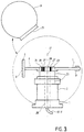
- Fig. 3 is a second embodiment of the invention Display device shown. The same elements are included with the same reference numerals as in the first embodiment 1 and 2 provided.
- the second exemplary embodiment according to FIG. 3 differs above all from the first embodiment described above in the way of attaching circuit board 4 and compensating element 7, 8 and the arrangement of the electrical connections.
- the coupling piece 3 replace the first embodiment of FIG. 1.
- the first fastening element 3a is the spring steel rod 7 of the Compensating element mounted while on the second fastener 3b the circuit board 4 with the control of the Device.
- the compensating element 7, 8 is in Principle like the compensating element 7, 8 described above Fig. 1 is built and is therefore not repeated at this point described in more detail.
- Circuit board 4 is analogous to the first embodiment the carrier 5 for the LEDs 6 attached.
- the electrical connections 9 of the circuit board 4 are through a bushing 26 through the base 1, the electric motor 2 and the drive shaft 20 to high-quality sliding contacts 27 supplied, which are for example and preferably made of gold.
- the Implementation 26 is firmly connected to the base 1 and not rotatable.
- the sliding contacts 27 are round rod-shaped at the top End of implementation 26 attached to the entire circumference.
- the Power is drawn via high-quality sliding contacts 28 made of gold on the fastening element 3b of the circuit board 4.
- the receiving opening 25 of the spherical body 19 only has to as large as the base 1 or the diameter of the electric motor Be 2.
- FIG. 4a shows the two basic elements spherical body 19 with a receiving opening 25 and completely pre-assembled assembly from electric motor 2, circuit board 4, carrier 5 with LEDs 6 and Compensation element 7, 8.
- the fully assembled and in the operating state located ball indicator shows Fig. 4h, here the Arrow 29 the direction of rotation of the drive shaft 20 and with it the Direction of rotation of the LED carrier 5 disclosed.
- the carrier 5 is attached the LEDs 6 obliquely through the receiving opening 25 of the spherical body 19 out.
- the spherical body 19 becomes something according to FIG. 4c rotated so that the receiving opening 25 is aligned horizontally is.
- the carrier 5 is completely in brought the spherical body 19 and the subsequent circuit board 4 so far into the receiving opening 25 until you Collar hits the side of the electric motor 2 or only one has a small side distance to the electric motor 2.
- the Ball body 19, as shown in FIGS. 4d to 4g by continuous rotation of its receiving opening 25 over the entire standing assembly tilted.
- the spring steel rod 7 or the one described above is equivalent Bar element with its weighted down by 8 End piece sags constantly and additionally continue to elastically bent into contact with the electric motor 2 can be, the relatively small diameter of the Receiving opening 25 from slipped over the entire assembly to become. After completely overturned spherical body 19 according to FIG. 4g, the spring steel rod 7 straightens up again or folds up again and engages.
- Fig. 4g shows the fully assembled ball display in the idle state.
- the electric motor rotates 2
- the drive shaft 20 which via the coupling piece 3 or Fasteners 3a and 3b with the circuit board 4
- the LED carrier 5 and the spring steel rod 7 is rotatably connected.
- the carrier 5 begins to rotate in the spherical body 19. Because of The spring steel rod is aligned with the increasing centrifugal force 7 or the equivalent rod element in the spherical body 19 to the horizontal position and forms in the operating state stabilization and equilibrium the device. That attached to the end of the spring steel rod 7 Weight 8 compensates for the weight of the LED arrangement used 5, 6.
- the entire LED ball display thus reaches one secure stand without special, additional fastenings requirement.
- the measuring device 15 designed as an optoelectronic measuring device.
- the optoelectronic measuring device can also be one with a Hall generator trained measuring device may be provided from a Hall sensor as a receiver and a permanent magnet exists as a transmitter. These components are close together on the stationary or rotating component of the device across from.
- the Hall sensor must not pass through the stray electrical field of the Electric motor 2 are disturbed. That's why you become one accordingly use insensitive Hall sensor or / and the Position or turn the Hall sensor so that it comes out of the electrical Stray field of the electric motor 2 comes.
Landscapes
- Engineering & Computer Science (AREA)
- Physics & Mathematics (AREA)
- General Physics & Mathematics (AREA)
- Theoretical Computer Science (AREA)
- Computer Hardware Design (AREA)
- Devices For Indicating Variable Information By Combining Individual Elements (AREA)
- Details Of Measuring Devices (AREA)
- Control Of Indicators Other Than Cathode Ray Tubes (AREA)
- Electrophonic Musical Instruments (AREA)
- Illuminated Signs And Luminous Advertising (AREA)
- Indicating Measured Values (AREA)
Claims (31)
- Dispositif d'affichage de caractères alphanumériques et/ou de symboles, comportant un boítier de révolution (19) en une matière transparente et/ou translucide et avec un axe de symétrie (21) ; un moteur électrique (2) disposé dans le boítier (19), avec un arbre d'entraínement (20) ; un support (5) solidaire en rotation de l'arbre d'entraínement (20) et tournant autour de l'axe de symétrie, sur lequel est ou sont prévu(s) une série de diodes luminescentes et/ou des groupes de diodes luminescentes (6), sensiblement perpendiculaire à l'axe de symétrie (21) ; et une plaquette de circuits (4) avec un circuit de commande pour les diodes luminescentes ou les groupes de diodes luminescentes (6),
caractérisé en ce que
la vitesse de rotation du support (5) est mesurée par un dispositif électronique de mesure (15) constitué d'un émetteur et d'un récepteur, que l'émetteur et le récepteur sont disposés face à face à faible distance l'un de l'autre d'une part sur une partie tournante du dispositif et d'autre part sur une partie fixe du dispositif et en ce que le signal capté par le récepteur peut être transformé au moyen d'un logiciel en un signal rectangulaire pur, libre d'influences perturbatrices extérieures, de sorte que la synchronisation de la commande des diodes luminescentes (6) s'effectue avec la vitesse de rotation du support (5) exactement ou à peu près exactement mesurée, support auquel est adjoint un élément d'équilibrage mécanique (7, 8) situé en face de lui par rapport à l'axe de symétrie (21). - Dispositif selon la revendication 1, caractérisé en ce que l'élément d'équilibrage (7, 8) est un barreau (7) de section indifférente dont la longueur active peut être raccourcie, qui prend en service une position sensiblement horizontale.
- Dispositif d'affichage de caractères alphanumériques et/ou de symboles, comportant un boítier de révolution (19) en une matière transparente et/ou translucide et avec un axe de symétrie (21); un moteur électrique (2) disposé dans le boítier (19), avec un arbre d'entraínement (20); un support (5) solidaire en rotation de l'arbre d'entraínement (20) et tournant autour de l'axe de symétrie, sur lequel est ou sont prévu(s) une série de diodes luminescentes et/ou des groupes de diodes luminescentes (6), sensiblement perpendiculaire à l'axe de symétrie (21); et une plaque de connexion avec un circuit de commande pour les diodes luminescentes ou les groupes de diodes luminescentes (6),
caractérisé en ce que
au support (5) est adjoint un élément d'équilibrage mécanique (7, 8) situé en face de lui par rapport à l'axe de symétrie (21) et en ce que l'élément d'équilibrage (7, 8) est un barreau (7) de section indifférente dont la longueur active peut être raccourcie, qui prend en service une position sensiblement horizontale. - Dispositif selon la revendication 3, caractérisé en ce qu'il est prévu un dispositif électronique de mesure (15) constitué d'un émetteur et d'un récepteur pour mesurer la vitesse de rotation du support (5) pour la synchronisation de la commande des diodes luminescentes (6) avec la vitesse de rotation du support (5), dont l'émetteur et le récepteur sont disposés face à face à faible distance l'un de l'autre d'une part sur une partie tournante du dispositif et d'autre part sur une partie fixe du dispositif, le signal capté par le récepteur pouvant être transformé au moyen d'un logiciel en un signal rectangulaire pur, libre d'influences perturbatrices extérieures, de sorte que la synchronisation de la commande des LEDs se fait avec la vitesse de rotation du support (5) exactement ou à peu près exactement mesurée.
- Dispositif selon l'une des revendications 1 à 4, caractérisé en ce que le dispositif de mesure (15) est un dispositif de mesure optoélectronique.
- Dispositif selon l'une des revendications 1 à 4, caractérisé en ce que le dispositif de mesure (15) est un générateur de Hall équipé d'un capteur de Hall comme récepteur, qui est en liaison active avec un aimant permanent comme émetteur, le capteur de Hall et l'aimant permanent sont disposés face à face à faible distance l'un de l'autre d'une part sur une partie tournante du dispositif et d'autre part sur une partie fixe du dispositif.
- Dispositif selon la revendication 5, caractérisé en ce que le dispositif de mesure optoélectronique (15) est constitué d'un photo capteur (16) d'un émetteur et d'un récepteur optoélectroniques et d'un réflecteur (17), le photo capteur (16) et le réflecteur (17) étant disposés face à face à faible distance l'un de l'autre d'une part sur une partie tournante du dispositif et d'autre part sur une partie fixe du dispositif.
- Dispositif selon l'une des revendications précédentes, caractérisé en ce que l'émetteur (22) et le récepteur (23) ou le photo capteur (16) et le réflecteur (17) ou le capteur de Hall et l'aimant permanent sont disposés face à face à faible distance l'un de l'autre d'une part sur un élément d'entraínement situé du côté du moteur et d'autre part sur un élément d'entraínement situé prés du support.
- Dispositif selon l'une des revendications précédentes, caractérisé en ce que l'émetteur est une diode émettrice (22).
- Dispositif selon l'une des revendications précédentes, caractérisé en ce que la plaquette de circuits (4) est reliée à une pièce de raccordement (3, 3b) ou au côté d'entraínement d'une pièce de raccordement (3, 3b).
- Dispositif selon la revendication 10, caractérisé en ce que la pièce de raccordement (3, 3b) est pourvue de contacts de frottement de très haute qualité (24, 28) pour la liaison électrique (9) de l'alimentation en énergie et de la transmission d'informations avec la plaquette de circuits (4).
- Dispositif selon l'une des revendications précédentes, caractérisé en ce qu'un passage (26) solidaire du socle (1) de l'unité d'entraínement est prévue est prévu pour permettre d'amener les fils électriques au moteur électrique (2) à travers l'arbre d'entraínement.
- Dispositif selon la revendication 12, caractérisé en ce que le passage (26) est pourvu de contacts de frottement (24) à sa partie supérieure arrondie, qui sont en liaison électrique avec les fils électriques (9).
- Dispositif selon la revendication 11 ou 13, caractérisé en ce qu'au moins la surface efficace des contacts de frottement (24, 28) est constituée d'or ou de cuivre graphite.
- Dispositif selon l'une des revendications précédentes, caractérisé en ce que le logiciel reconnaít et transmet chacun des signaux émergeant dans une série d'impulsion sinon régulière de signaux comme un signal de défaut.
- Dispositif selon l'une des revendications précédentes, caractérisé en ce que pour l'entrée de caractères alphanumériques et/ou de symboles à afficher, il est prévu au moins une jonction (11,14) entre le moyen d'entrée et le dispositif d'affichage.
- Dispositif selon la revendication 16, caractérisé en ce qu'une jonction est une interface (11) pour ordinateur afin de relier un ordinateur (12) au choix avec un terminal et un clavier ou uns souris.
- Dispositif selon la revendication 16 ou 17, caractérisé en ce qu'une jonction est un capteur infrarouges (14) pour recevoir les signaux infrarouges d'un dispositif de télécommande.
- Dispositif selon la revendication 18, caractérisé en ce que le dispositif d'affichage sert d'affichage de commande pour les caractères alphanumériques et/ou les symboles entrés par le dispositif de télécommande (13).
- Dispositif selon la revendication 18, caractérisé en ce que le capteur infrarouges (14) est fixé dans le boítier (19).
- Dispositif selon la revendication 18, caractérisé en ce que le capteur infrarouges (14) est disposé sur l'une des parties tournantes (5, 4) du dispositif.
- Dispositif selon l'une des revendications précédentes, caractérisé en ce que le moteur électrique (2) est pourvu d'un enroulement supplémentaire pour engendrer une basse tension pour les organes électriques.
- Dispositif selon l'une des revendications précédentes, caractérisé en ce que le moteur électrique (2) est monté sur un socle, un soubassement, un pied ou analogue (1) qui supporte des boítiers (19) sensiblement sphériques cylindriques ou plus généralement de révolution.
- Dispositif selon l'une des revendications précédentes, caractérisé en ce que les têtes des diodes luminescentes (6) sont taillées en biais pour obtenir un angle de lecture meilleur et plus grand.
- Dispositif selon l'une des revendications précédentes, caractérisé en ce que la pièce de raccordement (3) sert à la fixation mécanique par adaptation des parties tournantes (4, 5) sur l'arbre d'entraínement.
- Dispositif selon l'une des revendications précédentes, caractérisé en ce que la plaquette de circuits (4) sert de maintien mécanique pour le support (5) et en ce que l'élément d'équilibrage mécanique (7, 8) est fixé sur son extrémité dépassant au-delà de l'arbre d'entraínement (20).
- Dispositif selon l'une des revendications 2 à 26, caractérisé en ce que le bras de l'élément d'équilibrage (7, 8) est un barreau en acier à ressort ou un barreau en un matériaux présentant des caractéristiques identiques.
- Dispositif selon l'une des revendications 2 à 26, caractérisé en ce que le bras de l'élément d'équilibrage (7, 8) est un barreau repliable ou télescopique qui peut être bloqué à l'état de fonctionnement.
- Dispositif selon l'une des revendications 2 à 28, caractérisé en ce qu'à l'extrémité frontale libre du bras (7) ou près de celle-ci, est disposée une masse de valeur prédéterminée, qui peut être à volonté déplacée en direction longitudinale du bras (7) et arrêtée.
- Dispositif selon l'une des revendications précédentes, caractérisé en ce que l'ensemble constitué par le moteur électrique (2), l'arbre d'entraínement (20), la plaquette de circuits (4), les supports de LED (5) et l'élément d'équilibrage (7, 8) forme une unité complète et fonctionnelle prémontable, qui peut être installé comme un tout à travers l'ouverture d'introduction (25) du boítier (19).
- Dispositif selon l'une des revendications 6 à 30, caractérisé en ce que le capteur de Hall est insensible au champ de fuite du moteur électrique par sa structure et/ou sa position.
Applications Claiming Priority (5)
| Application Number | Priority Date | Filing Date | Title |
|---|---|---|---|
| DE29611155U | 1996-06-26 | ||
| DE29611155U DE29611155U1 (de) | 1996-06-26 | 1996-06-26 | Vorrichtung zur Anzeige von alpha-numerischen Zeichen und von Bildzeichen |
| DE29621296U DE29621296U1 (de) | 1996-12-07 | 1996-12-07 | Vorrichtung zur Anzeige von alpha-numerischen Zeichen und/oder Bildzeichen |
| DE29621296U | 1996-12-07 | ||
| PCT/EP1997/003145 WO1997050070A1 (fr) | 1996-06-26 | 1997-06-17 | Dispositif pour afficher des caracteres et des symboles alphanumeriques |
Publications (2)
| Publication Number | Publication Date |
|---|---|
| EP1004110A1 EP1004110A1 (fr) | 2000-05-31 |
| EP1004110B1 true EP1004110B1 (fr) | 2001-08-01 |
Family
ID=26059122
Family Applications (1)
| Application Number | Title | Priority Date | Filing Date |
|---|---|---|---|
| EP97928220A Expired - Lifetime EP1004110B1 (fr) | 1996-06-26 | 1997-06-17 | Dispositif pour afficher des caracteres et des symboles alphanumeriques |
Country Status (6)
| Country | Link |
|---|---|
| EP (1) | EP1004110B1 (fr) |
| AT (1) | ATE203846T1 (fr) |
| AU (1) | AU3259897A (fr) |
| DE (1) | DE59704216D1 (fr) |
| ES (1) | ES2162307T3 (fr) |
| WO (1) | WO1997050070A1 (fr) |
Families Citing this family (29)
| Publication number | Priority date | Publication date | Assignee | Title |
|---|---|---|---|---|
| GB9713035D0 (en) * | 1997-06-21 | 1997-08-27 | Margetson Guy E J | Visual display systems |
| GB2330679B (en) | 1997-10-21 | 2002-04-24 | 911 Emergency Products Inc | Warning signal light |
| KR20000005571A (ko) | 1998-06-03 | 2000-01-25 | 유길수 | 문자및/또는영상표시장치및방법 |
| US6380865B1 (en) * | 1999-04-06 | 2002-04-30 | 911 Emergency Products, Inc. | Replacement led lamp assembly and modulated power intensity for light source |
| US6462669B1 (en) | 1999-04-06 | 2002-10-08 | E. P . Survivors Llc | Replaceable LED modules |
| WO2000074972A1 (fr) | 1999-06-08 | 2000-12-14 | 911 Emergency Products, Inc. | Assemblage lumineux a del en bande |
| US6700502B1 (en) | 1999-06-08 | 2004-03-02 | 911Ep, Inc. | Strip LED light assembly for motor vehicle |
| US6705745B1 (en) | 1999-06-08 | 2004-03-16 | 911Ep, Inc. | Rotational led reflector |
| RU2173893C2 (ru) * | 1999-06-29 | 2001-09-20 | Дыбов Валерий Александрович | Способ получения объемного изображения объекта |
| RU2159962C1 (ru) * | 2000-03-13 | 2000-11-27 | Общество с ограниченной ответственностью Научно-производственная фирма "Альфа-Интек" | Вращающееся информационное устройство |
| US8188878B2 (en) | 2000-11-15 | 2012-05-29 | Federal Law Enforcement Development Services, Inc. | LED light communication system |
| US7439847B2 (en) | 2002-08-23 | 2008-10-21 | John C. Pederson | Intelligent observation and identification database system |
| US6943762B2 (en) | 2001-02-15 | 2005-09-13 | Newscanner, Plc | Visual message display device |
| US6816137B2 (en) | 2001-02-15 | 2004-11-09 | Newscanner, Plc | Visual message display device |
| GB0419071D0 (en) * | 2004-08-26 | 2004-09-29 | Mgx Internat Ltd | Display device |
| WO2008074899A1 (fr) * | 2006-12-21 | 2008-06-26 | Metalplast Cfe, S.L. | Affichage d'information tridimensionnelle |
| US9294198B2 (en) | 2007-05-24 | 2016-03-22 | Federal Law Enforcement Development Services, Inc. | Pulsed light communication key |
| US11265082B2 (en) | 2007-05-24 | 2022-03-01 | Federal Law Enforcement Development Services, Inc. | LED light control assembly and system |
| US9100124B2 (en) | 2007-05-24 | 2015-08-04 | Federal Law Enforcement Development Services, Inc. | LED Light Fixture |
| US9455783B2 (en) | 2013-05-06 | 2016-09-27 | Federal Law Enforcement Development Services, Inc. | Network security and variable pulse wave form with continuous communication |
| US9414458B2 (en) | 2007-05-24 | 2016-08-09 | Federal Law Enforcement Development Services, Inc. | LED light control assembly and system |
| US9258864B2 (en) | 2007-05-24 | 2016-02-09 | Federal Law Enforcement Development Services, Inc. | LED light control and management system |
| WO2008148039A1 (fr) | 2007-05-24 | 2008-12-04 | Federal Law Enforcement Development Services, Inc. | Système de communication à éclairage par del |
| US8890773B1 (en) | 2009-04-01 | 2014-11-18 | Federal Law Enforcement Development Services, Inc. | Visible light transceiver glasses |
| US9265112B2 (en) | 2013-03-13 | 2016-02-16 | Federal Law Enforcement Development Services, Inc. | LED light control and management system |
| US20150198941A1 (en) | 2014-01-15 | 2015-07-16 | John C. Pederson | Cyber Life Electronic Networking and Commerce Operating Exchange |
| US20170046950A1 (en) | 2015-08-11 | 2017-02-16 | Federal Law Enforcement Development Services, Inc. | Function disabler device and system |
| CN108648647A (zh) * | 2018-07-13 | 2018-10-12 | 珠海达其昌电子有限公司 | 一种旋转显示器及其装配方法 |
| CN115553800A (zh) * | 2022-10-26 | 2023-01-03 | 上海联影医疗科技股份有限公司 | Ct设备及其旋转控制方法、系统、介质 |
Family Cites Families (3)
| Publication number | Priority date | Publication date | Assignee | Title |
|---|---|---|---|---|
| US4689604A (en) * | 1983-03-03 | 1987-08-25 | S-V Development Ltd. | Moving visual display apparatus |
| GB8405760D0 (en) * | 1984-03-06 | 1984-04-11 | E Tek Ltd | Spacewriter programmer |
| GB8908322D0 (en) * | 1989-04-13 | 1989-06-01 | Stellar Communicat Ltd | Display |
-
1997
- 1997-06-17 EP EP97928220A patent/EP1004110B1/fr not_active Expired - Lifetime
- 1997-06-17 WO PCT/EP1997/003145 patent/WO1997050070A1/fr not_active Ceased
- 1997-06-17 AT AT97928220T patent/ATE203846T1/de not_active IP Right Cessation
- 1997-06-17 ES ES97928220T patent/ES2162307T3/es not_active Expired - Lifetime
- 1997-06-17 AU AU32598/97A patent/AU3259897A/en not_active Abandoned
- 1997-06-17 DE DE59704216T patent/DE59704216D1/de not_active Expired - Lifetime
Also Published As
| Publication number | Publication date |
|---|---|
| EP1004110A1 (fr) | 2000-05-31 |
| DE59704216D1 (de) | 2001-09-06 |
| ES2162307T3 (es) | 2001-12-16 |
| ATE203846T1 (de) | 2001-08-15 |
| AU3259897A (en) | 1998-01-14 |
| WO1997050070A1 (fr) | 1997-12-31 |
Similar Documents
| Publication | Publication Date | Title |
|---|---|---|
| EP1004110B1 (fr) | Dispositif pour afficher des caracteres et des symboles alphanumeriques | |
| DE69025183T2 (de) | Digitales lineares messgerät | |
| DE2839196B2 (de) | Anzeigevorrichtung für ein Anzeigeinstrument | |
| EP1290626A2 (fr) | Unite de positionnement | |
| DE2816302A1 (de) | Anzeigevorrichtung mit grenzwertmeldung | |
| DE29619984U1 (de) | Anzeigeeinrichtung mit geneigtem Lichtquellenträger | |
| DE2622395A1 (de) | Fernablesbarer magnetkompass | |
| DE9012303U1 (de) | Gerät zum Prüfen der Sehschärfe | |
| DE3003431A1 (de) | Vorrichtung zum abtasten von gegenstaenden | |
| EP0954840B1 (fr) | Dispositif pour afficher des caracteres alphanumeriques et/ou des symboles graphiques | |
| DE10026860B4 (de) | Anzeigevorrichtung für ein Kraftfahrzeug | |
| AT4976U1 (de) | Markenscheibe für einen drehwinkelaufnehmer, winkelaufnehmer für rotierende bauteile sowie verfahren zur ermittlung eines referenzwertes | |
| DE4119369A1 (de) | Uhr | |
| DE3931044C2 (fr) | ||
| DE29621296U1 (de) | Vorrichtung zur Anzeige von alpha-numerischen Zeichen und/oder Bildzeichen | |
| DE29704397U1 (de) | Vorrichtung zur Anzeige von alpha-numerischen Zeichen und/oder Bildzeichen | |
| EP1019748B1 (fr) | Dispositif de mesure optoelectronique | |
| DE2906950C3 (de) | Einrichtung zum Lenken eines externen Servomechanismus auf ein von einer Person anvisiertes Zielobjekt | |
| EP2579068B1 (fr) | Capteur destiné à la saisie d'objets dans une zone de surveillance | |
| LU103361B1 (de) | Tischtennisnetzeinrichtung | |
| DE8913965U1 (de) | Optoelektronische Einrichtung | |
| DE3435504A1 (de) | Kompass | |
| DE19757957C2 (de) | Motorisiertes Nivelliergerät | |
| DE19514120C2 (de) | Bohrloch-Vermessungsgerät | |
| DE19810683A1 (de) | Vorrichtung zur Anzeige von alpha-numerischen Zeichen und/oder Bildzeichen |
Legal Events
| Date | Code | Title | Description |
|---|---|---|---|
| PUAI | Public reference made under article 153(3) epc to a published international application that has entered the european phase |
Free format text: ORIGINAL CODE: 0009012 |
|
| 17P | Request for examination filed |
Effective date: 19990415 |
|
| AK | Designated contracting states |
Kind code of ref document: A1 Designated state(s): AT BE CH DE DK ES FI FR GB GR IE IT LI LU MC NL PT SE |
|
| GRAG | Despatch of communication of intention to grant |
Free format text: ORIGINAL CODE: EPIDOS AGRA |
|
| 17Q | First examination report despatched |
Effective date: 20001004 |
|
| GRAG | Despatch of communication of intention to grant |
Free format text: ORIGINAL CODE: EPIDOS AGRA |
|
| GRAH | Despatch of communication of intention to grant a patent |
Free format text: ORIGINAL CODE: EPIDOS IGRA |
|
| GRAH | Despatch of communication of intention to grant a patent |
Free format text: ORIGINAL CODE: EPIDOS IGRA |
|
| GRAA | (expected) grant |
Free format text: ORIGINAL CODE: 0009210 |
|
| AK | Designated contracting states |
Kind code of ref document: B1 Designated state(s): AT BE CH DE DK ES FI FR GB GR IE IT LI LU MC NL PT SE |
|
| PG25 | Lapsed in a contracting state [announced via postgrant information from national office to epo] |
Ref country code: FI Free format text: LAPSE BECAUSE OF FAILURE TO SUBMIT A TRANSLATION OF THE DESCRIPTION OR TO PAY THE FEE WITHIN THE PRESCRIBED TIME-LIMIT Effective date: 20010801 |
|
| REF | Corresponds to: |
Ref document number: 203846 Country of ref document: AT Date of ref document: 20010815 Kind code of ref document: T |
|
| REG | Reference to a national code |
Ref country code: CH Ref legal event code: EP |
|
| REG | Reference to a national code |
Ref country code: IE Ref legal event code: FG4D Free format text: GERMAN |
|
| REF | Corresponds to: |
Ref document number: 59704216 Country of ref document: DE Date of ref document: 20010906 |
|
| PG25 | Lapsed in a contracting state [announced via postgrant information from national office to epo] |
Ref country code: SE Free format text: LAPSE BECAUSE OF FAILURE TO SUBMIT A TRANSLATION OF THE DESCRIPTION OR TO PAY THE FEE WITHIN THE PRESCRIBED TIME-LIMIT Effective date: 20011101 Ref country code: DK Free format text: LAPSE BECAUSE OF FAILURE TO SUBMIT A TRANSLATION OF THE DESCRIPTION OR TO PAY THE FEE WITHIN THE PRESCRIBED TIME-LIMIT Effective date: 20011101 |
|
| PG25 | Lapsed in a contracting state [announced via postgrant information from national office to epo] |
Ref country code: GR Free format text: LAPSE BECAUSE OF FAILURE TO SUBMIT A TRANSLATION OF THE DESCRIPTION OR TO PAY THE FEE WITHIN THE PRESCRIBED TIME-LIMIT Effective date: 20011102 |
|
| PG25 | Lapsed in a contracting state [announced via postgrant information from national office to epo] |
Ref country code: PT Free format text: LAPSE BECAUSE OF FAILURE TO SUBMIT A TRANSLATION OF THE DESCRIPTION OR TO PAY THE FEE WITHIN THE PRESCRIBED TIME-LIMIT Effective date: 20011105 |
|
| GBT | Gb: translation of ep patent filed (gb section 77(6)(a)/1977) |
Effective date: 20011102 |
|
| REG | Reference to a national code |
Ref country code: CH Ref legal event code: NV Representative=s name: A. BRAUN, BRAUN, HERITIER, ESCHMANN AG PATENTANWAE |
|
| REG | Reference to a national code |
Ref country code: ES Ref legal event code: FG2A Ref document number: 2162307 Country of ref document: ES Kind code of ref document: T3 |
|
| ET | Fr: translation filed | ||
| REG | Reference to a national code |
Ref country code: GB Ref legal event code: IF02 |
|
| PGFP | Annual fee paid to national office [announced via postgrant information from national office to epo] |
Ref country code: ES Payment date: 20020607 Year of fee payment: 6 |
|
| PLBE | No opposition filed within time limit |
Free format text: ORIGINAL CODE: 0009261 |
|
| STAA | Information on the status of an ep patent application or granted ep patent |
Free format text: STATUS: NO OPPOSITION FILED WITHIN TIME LIMIT |
|
| PGFP | Annual fee paid to national office [announced via postgrant information from national office to epo] |
Ref country code: AT Payment date: 20020612 Year of fee payment: 6 |
|
| PG25 | Lapsed in a contracting state [announced via postgrant information from national office to epo] |
Ref country code: MC Free format text: LAPSE BECAUSE OF NON-PAYMENT OF DUE FEES Effective date: 20020617 Ref country code: LU Free format text: LAPSE BECAUSE OF NON-PAYMENT OF DUE FEES Effective date: 20020617 Ref country code: IE Free format text: LAPSE BECAUSE OF NON-PAYMENT OF DUE FEES Effective date: 20020617 Ref country code: GB Free format text: LAPSE BECAUSE OF NON-PAYMENT OF DUE FEES Effective date: 20020617 |
|
| PG25 | Lapsed in a contracting state [announced via postgrant information from national office to epo] |
Ref country code: LI Free format text: LAPSE BECAUSE OF NON-PAYMENT OF DUE FEES Effective date: 20020630 Ref country code: CH Free format text: LAPSE BECAUSE OF NON-PAYMENT OF DUE FEES Effective date: 20020630 Ref country code: BE Free format text: LAPSE BECAUSE OF NON-PAYMENT OF DUE FEES Effective date: 20020630 |
|
| 26N | No opposition filed | ||
| BERE | Be: lapsed |
Owner name: *LUMINO LICHT ELEKTRONIK G.M.B.H. Effective date: 20020630 |
|
| PG25 | Lapsed in a contracting state [announced via postgrant information from national office to epo] |
Ref country code: NL Free format text: LAPSE BECAUSE OF NON-PAYMENT OF DUE FEES Effective date: 20030101 |
|
| GBPC | Gb: european patent ceased through non-payment of renewal fee |
Effective date: 20020617 |
|
| REG | Reference to a national code |
Ref country code: CH Ref legal event code: PL |
|
| PG25 | Lapsed in a contracting state [announced via postgrant information from national office to epo] |
Ref country code: FR Free format text: LAPSE BECAUSE OF NON-PAYMENT OF DUE FEES Effective date: 20030228 |
|
| NLV4 | Nl: lapsed or anulled due to non-payment of the annual fee |
Effective date: 20030101 |
|
| REG | Reference to a national code |
Ref country code: IE Ref legal event code: MM4A |
|
| REG | Reference to a national code |
Ref country code: FR Ref legal event code: ST |
|
| PG25 | Lapsed in a contracting state [announced via postgrant information from national office to epo] |
Ref country code: AT Free format text: LAPSE BECAUSE OF NON-PAYMENT OF DUE FEES Effective date: 20030617 |
|
| PG25 | Lapsed in a contracting state [announced via postgrant information from national office to epo] |
Ref country code: ES Free format text: LAPSE BECAUSE OF NON-PAYMENT OF DUE FEES Effective date: 20030618 |
|
| REG | Reference to a national code |
Ref country code: ES Ref legal event code: FD2A Effective date: 20030618 |
|
| PG25 | Lapsed in a contracting state [announced via postgrant information from national office to epo] |
Ref country code: IT Free format text: LAPSE BECAUSE OF NON-PAYMENT OF DUE FEES;WARNING: LAPSES OF ITALIAN PATENTS WITH EFFECTIVE DATE BEFORE 2007 MAY HAVE OCCURRED AT ANY TIME BEFORE 2007. THE CORRECT EFFECTIVE DATE MAY BE DIFFERENT FROM THE ONE RECORDED. Effective date: 20050617 |
|
| PGFP | Annual fee paid to national office [announced via postgrant information from national office to epo] |
Ref country code: DE Payment date: 20110615 Year of fee payment: 15 |
|
| REG | Reference to a national code |
Ref country code: DE Ref legal event code: R119 Ref document number: 59704216 Country of ref document: DE Effective date: 20130101 |
|
| PG25 | Lapsed in a contracting state [announced via postgrant information from national office to epo] |
Ref country code: DE Free format text: LAPSE BECAUSE OF NON-PAYMENT OF DUE FEES Effective date: 20130101 |