EP1004185B1 - Procede et systeme d'interconnexion de reseaux en anneaux - Google Patents
Procede et systeme d'interconnexion de reseaux en anneaux Download PDFInfo
- Publication number
- EP1004185B1 EP1004185B1 EP98928755A EP98928755A EP1004185B1 EP 1004185 B1 EP1004185 B1 EP 1004185B1 EP 98928755 A EP98928755 A EP 98928755A EP 98928755 A EP98928755 A EP 98928755A EP 1004185 B1 EP1004185 B1 EP 1004185B1
- Authority
- EP
- European Patent Office
- Prior art keywords
- ring
- node
- ring network
- gateway
- nodes
- Prior art date
- Legal status (The legal status is an assumption and is not a legal conclusion. Google has not performed a legal analysis and makes no representation as to the accuracy of the status listed.)
- Expired - Lifetime
Links
- 238000000034 method Methods 0.000 title claims abstract description 12
- 238000004891 communication Methods 0.000 claims abstract description 28
- 230000005540 biological transmission Effects 0.000 claims description 22
- 238000001514 detection method Methods 0.000 claims description 8
- 230000007246 mechanism Effects 0.000 claims description 6
- 230000011664 signaling Effects 0.000 abstract description 2
- 239000000835 fiber Substances 0.000 description 12
- 230000003287 optical effect Effects 0.000 description 9
- 238000010586 diagram Methods 0.000 description 3
- 230000003321 amplification Effects 0.000 description 2
- 230000000903 blocking effect Effects 0.000 description 2
- 238000003199 nucleic acid amplification method Methods 0.000 description 2
- 239000013307 optical fiber Substances 0.000 description 2
- 238000011144 upstream manufacturing Methods 0.000 description 2
- 230000008859 change Effects 0.000 description 1
- 230000000295 complement effect Effects 0.000 description 1
- 230000009849 deactivation Effects 0.000 description 1
- 238000005516 engineering process Methods 0.000 description 1
- 230000004048 modification Effects 0.000 description 1
- 238000012986 modification Methods 0.000 description 1
- 230000010355 oscillation Effects 0.000 description 1
- 230000008569 process Effects 0.000 description 1
- 230000002269 spontaneous effect Effects 0.000 description 1
Images




Classifications
-
- H—ELECTRICITY
- H04—ELECTRIC COMMUNICATION TECHNIQUE
- H04J—MULTIPLEX COMMUNICATION
- H04J14/00—Optical multiplex systems
- H04J14/02—Wavelength-division multiplex systems
- H04J14/0287—Protection in WDM systems
- H04J14/0293—Optical channel protection
-
- H—ELECTRICITY
- H04—ELECTRIC COMMUNICATION TECHNIQUE
- H04J—MULTIPLEX COMMUNICATION
- H04J14/00—Optical multiplex systems
- H04J14/02—Wavelength-division multiplex systems
- H04J14/0227—Operation, administration, maintenance or provisioning [OAMP] of WDM networks, e.g. media access, routing or wavelength allocation
-
- H—ELECTRICITY
- H04—ELECTRIC COMMUNICATION TECHNIQUE
- H04J—MULTIPLEX COMMUNICATION
- H04J14/00—Optical multiplex systems
- H04J14/02—Wavelength-division multiplex systems
- H04J14/0227—Operation, administration, maintenance or provisioning [OAMP] of WDM networks, e.g. media access, routing or wavelength allocation
- H04J14/0241—Wavelength allocation for communications one-to-one, e.g. unicasting wavelengths
-
- H—ELECTRICITY
- H04—ELECTRIC COMMUNICATION TECHNIQUE
- H04J—MULTIPLEX COMMUNICATION
- H04J14/00—Optical multiplex systems
- H04J14/02—Wavelength-division multiplex systems
- H04J14/0278—WDM optical network architectures
- H04J14/0283—WDM ring architectures
-
- H—ELECTRICITY
- H04—ELECTRIC COMMUNICATION TECHNIQUE
- H04J—MULTIPLEX COMMUNICATION
- H04J14/00—Optical multiplex systems
- H04J14/02—Wavelength-division multiplex systems
- H04J14/0278—WDM optical network architectures
- H04J14/0286—WDM hierarchical architectures
-
- H—ELECTRICITY
- H04—ELECTRIC COMMUNICATION TECHNIQUE
- H04J—MULTIPLEX COMMUNICATION
- H04J14/00—Optical multiplex systems
- H04J14/02—Wavelength-division multiplex systems
- H04J14/0287—Protection in WDM systems
- H04J14/0289—Optical multiplex section protection
-
- H—ELECTRICITY
- H04—ELECTRIC COMMUNICATION TECHNIQUE
- H04L—TRANSMISSION OF DIGITAL INFORMATION, e.g. TELEGRAPHIC COMMUNICATION
- H04L12/00—Data switching networks
- H04L12/28—Data switching networks characterised by path configuration, e.g. LAN [Local Area Networks] or WAN [Wide Area Networks]
- H04L12/46—Interconnection of networks
- H04L12/4637—Interconnected ring systems
-
- H—ELECTRICITY
- H04—ELECTRIC COMMUNICATION TECHNIQUE
- H04J—MULTIPLEX COMMUNICATION
- H04J14/00—Optical multiplex systems
- H04J14/02—Wavelength-division multiplex systems
- H04J14/0287—Protection in WDM systems
- H04J14/0297—Optical equipment protection
Definitions
- the present invention relates to a method and a system for protecting an interconnection between ring networks.
- Wave Division Multiplexing is a technology allowing the transmission of a number of optical signals through an optical fibre using different separated light wavelengths. In this way the information carrying capacity may be increased significantly.
- the capacity depends on the number of used wavelength channels and their bandwidth. The signal at each wavelength travels through the fibre irrespectively of the other signals, so that each signal represents a discrete channel with large bandwidth.
- a ring communication network is made up of nodes, which are connected in tandem in a ring by a unidirectional communication path, such as an optical fibre.
- a node receives transmissions from an upstream node. The return traffic is transmitted downstream to the first node.
- a drawback of such a network is that a break in the ring or a failure of a node would prevent any node upstream of the break/failure to communicate with any node downstream of the break.
- a usual solution to this problem is to in some way provide a second spare communication path parallel to the first, but in the opposite direction, see US 5,365,510, US 5,179,548 and EP 677,936. If communication fails somewhere on the first communication path, then the traffic is directed back on the second communication path and the wished node will thus be reached from the other side.
- a ring network consists, in this case, of two parallel communication paths, of which one carries traffic in the clockwise direction and the other carries the same traffic in the counterclockwise direction.
- the two serving nodes then retransmit the received signals in a second ring network.
- Each serving node transmits away from the other serving node, with the result that the two communication paths in the second ring network carry the same traffic.
- the node to which the traffic is sent uses a selector to select from which communication path signals will be received.
- a purpose with the present invention is to provide a protected interconnection between ring networks.
- a ring network will for short be called a "ring".
- the protection is done by using two parallel interconnecting nodes on a ring, which are coupled with two corresponding parallel interconnecting nodes on another ring and are called gateways. Signals entering a ring are routed across both gateways.
- a gateway may receive signals from both directions of the ring, but only transmits away from the neighbouring gateway.
- the present invention solves the problem by using a different kind of nodes than the nodes in US 5,218,604 and in particularly by each ring comprising an inactive segment.
- the inactive segment ensures that nodes on the ring only receive signals from one of the gateways. In the event of a fault the inactive segment moves so it encompasses the fault. Hence, operation is ensured.
- one of the gateways features a detection mechanism that detects the situation. If the situation occurs, said gateway suppresses transmission and just the other gateway transmits.
- One of the gateways transmit always both in the upper and the lower part of the ring, using different wavelengths in the different parts, as mentioned.
- the other gateway transmit only in the part where the inactive segment is situated.
- the other gateway knows in which part of the ring to transmit and not due to the detection mechanism described above.
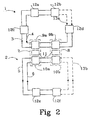
- a first ring network 1 comprising two optical fibres 3 and 4 and a second ring network 2 comprising two optical fibres 5 and 6.
- a ring network will for short be called a "ring”.
- the two fibres 3 and 4 or 5 and 6 work in opposite directions, which is indicated with arrows in the figure.
- the two rings 1 and 2 are interconnected via a first gateway 7 to the left and a second gateway 8 to the right.
- Each gateway 7, 8 comprises a gateway node 9a, 9b, 10a, 10b on each ring 1, 2 and optionally some kind of crossconnect 11 between the two gateway nodes 9a, 9b, 10a, 10b.
- the rings 1, 2 each comprises an inactive segment 13, which is shown schematically as two dashed lines in the figures.
- the inactive segment may be situated anywhere on the ring 1, 2, but in the case of a fault the inactive segment 13 will move to the fault.
- the inactive segment 13 on the ring 1 is situated between the nodes 12a and 12c, which thus become end nodes of a bus.
- the inactive segment 13 has arisen, because the two end nodes 12a and 12c both block reception from or transmission towards the place of the wished inactive segment. Examples regarding how to implement inactive segments will be given below.
- Each gateway 7, 8 receives traffic from both directions, that is both fibres 4 and 5 or 6 and 7 in the ring 1 or 2.
- the gateway 7, 8 only transmits away from its partner gateway 8, 7, which is shown in figure 1b.
- no nodes 12a-f should, in this first embodiment, lie on the direct path between the two gateways 7, 8.
- each node 12a-f only receives traffic from one of the gateways 7, 8.
- the nodes 12c that are situated counterclockwise from the inactive segment 13 will receive traffic from the left gateway 7, whereas the nodes 12a, 12b, 12d that are situated clockwise from the inactive segment 13 will receive traffic from the right gateway 8.
- the transmission will pass the node 12e and reach the left gateway 7, where it is splitted.
- One part of the transmission is received in the left gateway 7 for retransmission in the upper ring 1 and the other part continues to the right gateway 8, where it is also received for retransmission in the upper ring 1.
- the left gateway 7 retransmits in the upper ring 1 away from the right gateway 8, that is following the fibre 4 clockwise.
- the transmission then passes the node 12c and then - there is a stop, because the inactive segment 13a is situated between the nodes 12a and 12c, which are thus acting as end nodes in the ring.
- the right gateway 8 retransmits in the upper ring 1 away from the left gateway 7, that is following the fibre 3 counterclockwise. The transmission then passes the nodes 12d and 12b and ends up in the wished node 12a.
- inactive segment 13a had been situated between the nodes 12b and 12d instead, like in figure 2, it would instead have been the transmission from the left gateway 7 that had reached the wished node 12a - via the node 12c.
- the node is connected to the two fibres 3, 4.
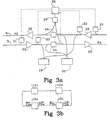
- the node comprises a first detector 21, a preamplifier 22, a second detector 23, a switch 24, a booster amplifier 25, a group of receivers 19 and a group of transmitters 20.
- the groups of receivers 19 and transmitters 20 will for simplicity consequently be drawn as one block each.
- the amplifiers 22 and 25 are not necessary for the invention as such, but it is conceivable that they could work as switches and replace or complement the switch 24.
- the first detector 21 detects loss of incoming power and the second detector 23 detects loss of incoming protection signals.
- the switch 24 is used to get an inactive segment.
- the transmitters 20 and the receivers 19 are used to add and drop channels to and from the ring.
- a central processor 26 controls everything and a protection signal transmitter 27 sends a protection signal PS on both the fibres 3, 4, that is in both directions, when the node acts as an end node.
- figure 3b is schematically shown a ring with four nodes 12a, 12b, 12c, 12d as in figure 3a.
- An inactive segment 13 lies between the end nodes 12a and 12b.
- the end nodes 12a and 12b both have their switch 24 towards the inactive segment 13 closed. That means that, as a main rule, no data traffic can be transmitted over the inactive segment 13.
- both end nodes 12a, 12b transmit protection signals PSa and PSb, respectively, in both directions, that is also over the inactive segment 13.
- PSa and PSb transmitted counterclockwise are labelled PSa' and PSb'.
- the transmission of the protection signal PS occurs after the switch 24 and is thus not influenced of the state of the switch 24. This means that in a normal state each node 12a, 12b, 12c, 12d will receive four protection signals PSa, PSb, PSa' and PSb'.
- the left end node 12a receives its own protection signal PSa' and the protection signal PSb' from the right end node 12b, but does not receive the protection signal PSb from the right end node 12b, then there is probably a fault on the fibre going over the inactive segment 13 from the right end node 12b to the left end node 12a.
- the left end node 12a does not receive its own protection signal PSa' and not receives the protection signal PSb' from the right end node 12b, but receives the protection signal PSb from the right end node 12b, then there is probably a fault on the fibre but not in the inactive segment 13. This is an indication on that the inactive segment 13 should be moved.
- the left end node 12a receives its own protection signal Psa', but not receives the protection signal PSb' from the right end node 12b, then there is probably a fault in the right end node 12b, but not in the inactive segment 13 and thus the inactive segment 13 should be moved.
- the end nodes 12a, 12b will stop sending their protection signals PSa, PSa', PSb, PSb' and open their switches towards the inactive segment 13. Thus transmission is possible over the now former inactive segment 13.
- the node 12c detects loss of incoming power by means of its first detector 21 on one side it is an indication of a fault on that side. Therefore the switch 24 on the fibre going towards that side closes and protection signals PSc starts to be transmitted in both directions. The corresponding will happen on the other side of the fault and thus a new inactive segment is created.
- a fault occurring in a node instead of between two nodes may be taken care of in a corresponding way.
- figure 4a are shown the parts of a node that are relevant for the invention. Much is the same as in the first embodiment and only the differences will be marked.
- the node is connected to the two fibres 3, 4. On each fibre 3, 4 the node comprises the detector 21, the preamplifier 22, the booster amplifier 25, the receivers 19 and the transmitters 20.
- the detector 21 detects loss of incoming power and the preamplifier 22 works as a switch.
- the central processor 26 controls everything and a supervision unit 28 sends an alarm signal SS on both fibres 3, 4 in a separate wavelength channel.
- the alarm signal SS is sent circling around the ring from node to node in both directions all the time.
- the alarm signal SS is a fault flag, which is set in the case of a fault. In that case there is also an indication in the wavelength channel on which section is inactive.
- the inactive segment is achieved by shut off preamplifiers blocking reception in the end nodes from the inactive segment.
- the booster amplifiers to block transmission instead of using the preamplifiers to block reception.
- advantages of blocking reception because then signals are present at the input of the shut off preamplifier. This means that a fault occurring in the present inactive segment may be detected by loss of power. It also means that the signals may be used to adjust the future amplification of the preamplifier, so that when the preamplifier is turned on it will have the correct amplification at once.
- both the preamplifier and the booster amplifier in the direction towards the fault will shut off like a switch.
- One reason for shutting off also the booster amplifiers is for ensuring a segment deactivation in the case of unidirectional faults. Another reason is for human eye safety reasons.
- said node becomes an end node and a new inactive segment will be created much like the process in the first embodiment.
- the alarm signal SS will be set in the supervision channel.
- the node on the other side of the fault will also try to set the same alarm signal SS, which gives a redundancy in case of node faults.
- the other nodes When the other nodes receive the set alarm signal SS they will know that a fault has occurred.
- the former end nodes, which had their preamplifiers shut off towards the inactive segment will now activate their preamplifiers.
- the inactive segment is moved, much in the same way as in the first embodiment.
- the set alarm signal SS will also prevent the inactive segment to move a second time before the fault has been repaired, because moving is only allowed if the alarm signal SS is not set.
- the supervision channel may also perform other types of signalling at the same time.
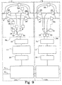
- FIG 5 a pair of gateways nodes 9a, 9b are shown. They contain all the features of the nodes in figure 3a but with some extra features. For the sake of clarity only the most relevant features will be shown in figure 5. The extra features may also be implemented in figure 4a, but using the preamplifier instead of the switch, see figure 6. Only figure 5 will be described. Figure 6 will work in a corresponding way.
- control signals goes normally via the not shown central processor, compare figure 3a and 4a.
- the gateway 7, 8 comprises the two gateway nodes 9a, 10a, 9b, 10b with the optional crossconnect 11 between the gateway nodes 9a, 10a.
- the gateway nodes 9a, 9b is shown.
- the other gateway node 10a, 10b is similar.
- the first gateway node 9a, 9b in the gateway 7, 8 are connected to both the clockwise fibre 4 and the counterclockwise fibre 3. Traffic from the first fibres 3, 4 towards the two second fibres 5, 6 in another ring, is received in receivers 30. The traffic then goes via a first terminal multiplexer 31, the optional crossconnect 11, and a second terminal multiplexer 32 to the second gateway node 10a, 10b, which is connected co the two second fibres 5, 6.
- Traffic from the second gateway node 10a, 10b to the first gateway node 9a, 9b goes in the opposite direction and is retransmitted in the first fibres 3, 4 by transmitters 33 in the first gateway node 9a, 9b.
- a third detector 34 or a group of detectors 34, one per channel, detects if there is a loss of incoming power from the second terminal multiplexer 32, which indicates a fault and closes the switch 24. The fault handling described above occurs.
- gateway nodes 9a, 9b, 10a, 10b always receive traffic from both fibres in the same ring, but only transmit away from its neighbouring gateway node. Together with the inactive segment this ensures that a node in a ring only receives traffic from one of the gateways.
- the left gateway 7 in figure 5 comprises a condition detector 35, which may be the same as the second detector 23 not facing the right gateway 8. If the condition detector 35 detects a protection signal PS from the right gateway 8, the left gateway 7 suppresses transmission in the ring 1 in question by closing a switch 36. However, the left gateway 7 continues to receive traffic as usual and will stand-by for transmission. In the case of a subsequent failure in the right gateway 8, the left gateway 7 will detect that the protection signal PS is missing and will start transmitting again.
- information is sent in the supervision channel on in which segment the fault has occurred, which may be detected by the supervision unit 28 in the left gateway.
- FIG 8 is the same as figure 5 and figure 9 is the same as figure 6, but with additional connections which makes it possible for the gateway nodes 9a, 9b to transmit in both directions. Only figure 8 will be described, but figure 9 will work in a corresponding way. It is to be understood that in figures 8 and 9 the gateways are drawn next to each other by the sole reason of lack of space on the paper. The gateways are primarily meant to be used with nodes between them.
- condition detector 37 which may be the same as the other second detector 23, serving the same purpose as the condition detector 35 mentioned above, that is to put a switch 38 in an off position in the case of a discovered protection signal. Either there may be two switches 36, 38 as drawn in figure 8, or else one switch that switches the one transmission line or the other. In this last version, however, the left gateway will not be in standby for the right gateway.
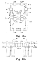
- FIGS 10a and 10c depict the same network as in figures 1a, 3 and 7, but with the nodes 12c and 12d between the gateway nodes 9a, 9b instead.
- Figure 10b shows how the gateway nodes work schematically.
- the ring will be "separated” in an upper part U and a lower part L.
- “Separated” means that a gateway node 9a, 9b will in the upper part U of the ring only transmit traffic destined for the nodes in the upper part U of the ring and will in the lower part L of the ring only transmit traffic destined for the nodes in the lower part L of the ring. Note that in order to make it work properly, different wavelengths ⁇ 1, ⁇ 2 and ⁇ 3, ⁇ 4 should be used in the two parts U, L of the ring.
- the inactive segment 13 is positioned between the nodes 12c and 12d in the lower part L of the ring.
- both gateway nodes 9a, 9b transmit in the lower part L of the ring, while only the right gateway node 9b transmit in the upper part U of the ring.
- the left gateway 9a will detect that the right gateway node 9b is transmitting in the upper part U of the ring and thus the left gateway 9a blocks transmission in that direction.
- the inactive segment 13 is positioned between the nodes 12a and 12b in the upper part U of the ring.
- both gateway nodes 9a, 9b transmit in the upper part U of the ring, while only the right gateway node 9b transmit in the lower part L of the ring.
- the left gateway 9a will detect that the right gateway node 9b is transmitting in the lower part L of the ring and thus the left gateway 9a blocks transmission in that direction.
- a fault occurring in one of the gateways 7, 8 gives no more problem than any other fault. Since the two gateways 7, 8 are redundant it will be like using just one gateway 7 and with an inactive segment next to the faulty gateway 8.
- This method also works with more than two rings and even though only optical embodiments are shown it will work in a similar manner in an electrical network.
Landscapes
- Engineering & Computer Science (AREA)
- Computer Networks & Wireless Communication (AREA)
- Signal Processing (AREA)
- Small-Scale Networks (AREA)
- Time-Division Multiplex Systems (AREA)
- Computer And Data Communications (AREA)
Claims (10)
- Procédé pour protéger une interconnexion entre des réseaux en anneau (1, 2), où des signaux sont transmis entre au moins deux réseaux en anneau (1, 2), dans lequel chaque réseau en anneau (1, 2) comprend deux trajets de communication (3, 4, 5, 6) fonctionnant dans des directions opposées et au moins un noeud (12a, 12b, 12c, 12d, 9, 12e, 12f, 10) connecté aux deux trajets de communication (3, 4, 5, 6), dans lequel les deux réseaux en anneau (1, 2) sont interconnectés via deux passerelles (7, 8), chaque passerelle (7, 8) étant conçue pour recevoir le trafic depuis les deux trajets de communication (3, 4, 5, 6) sur un réseau en anneau (1, 2) et pour transmettre ledit trafic vers l'autre réseau en anneau (1, 2) sur le trajet de communication (3, 4, 5, 6) dirigé vers une première partie (U) du réseau en anneau (1, 2), caractérisé en ce que le trafic est arrêté dans les deux directions dans un segment, appelé segment inactif (13a, 13b), entre deux noeuds (12a, 12b, 12c, 12d, 9, 12e, 12f, 10) sur chaque réseau en anneau (1, 2), et
en ce qu'un mécanisme de détection (23, 35, 37) est prévu qui détecte si la position du segment inactif (13a, 13b) est telle qu'un noeud dans une partie (U, L) du réseau en anneau reçoit le trafic depuis les deux passerelles (7, 8). - Procédé selon la revendication 1, caractérisé en ce que si le segment inactif (13a, 13b) est dans la position où un noeud dans une partie (U, L) du réseau en anneau reçoit le trafic depuis les deux passerelles (7, 8), alors la transmission est supprimée dans ladite partie (U, L) du réseau.
- Procédé selon la revendication 1 ou 2, caractérisé en ce que le segment inactif (13a, 13b) est atteint lorsque les deux noeuds (12a, 12b, 12c, 12d, 9, 12e, 12f, 10) sur chaque côté du segment inactif (13a, 13b) sur un réseau en anneau (1, 2) sont des noeuds d'extrémité et suppriment la réception depuis, ou la transmission vers, la direction du segment inactif (13a, 13b).
- Procédé selon la revendication 3, caractérisé en ce que si une défaillance se produit sur le réseau en anneau (1, 2) à tout endroit quelconque autre que dans le segment inactif (13a, 13b), alors le segment inactif (13a, 13b) est déplacé logiquement vers la défaillance.
- Procédé selon la revendication 4, caractérisé en ce que chaque noeud d'extrémité (12a, 12b, 12c, 12d, 9, 12e, 12f, 10) transmet un signal de protection propre (PSa, PSb) sur les deux trajets de communication (3, 4, 5, 6) connectés au noeud d'extrémité (12a, 12b, 12c, 12d, 9, 12e, 12f, 10), en ce que les signaux de protection (PSa, PSb) ne sont pas arrêtés par le segment inactif (13a, 13b), en ce que chaque noeud d'extrémité (12a, 12b, 12c, 12d, 9, 12e, 12f, 10) détecte la présence des signaux de protection (PSa, PSb) et en ce qu'une détection de défaillance est effectuée à partir de la détection du signal de protection.
- Procédé selon la revendication 4, caractérisé en ce qu'un indicateur d'alarme (SS) est envoyé dans son propre canal sur les deux trajets de communication (3, 4, 5, 6) de noeud à noeud, en ce que l'indicateur d'alarme (SS) n'est pas arrêté par le segment inactif (13a, 13b), et en ce que l'indicateur d'alarme (SS) est établi si une défaillance est détectée sur le réseau en anneau (1, 2).
- Procédé selon l'une quelconque des revendications 1 à 6, caractérisé en ce que chaque passerelle (7, 8) transmet le trafic vers l'autre réseau en anneau (1, 2) également sur le trajet de communication (3, 4, 5, 6) dirigé vers une seconde partie (L) du réseau, à moins que ce ne soit prohibé en conformité avec ledit mécanisme de détection.
- Système pour protéger une interconnexion entre des réseaux en anneau, comprenant deux réseaux en anneau (1, 2), chaque réseau en anneau (1, 2) comprenant deux trajets de communication (3, 4, 5, 6) agissant dans des directions opposées et au moins un noeud (12a, 12b, 12c, 12d, 9, 12e, 12f, 10) connecté aux trajets de communication (3, 4, 5, 6), lesdits deux réseaux en anneau (1, 2) étant interconnectés via deux passerelles (7, 8), chaque passerelle (7, 8) étant conçue pour recevoir le trafic depuis les deux trajets de communication (3, 4, 5, 6) sur un réseau en anneau (1, 2) et pour transmettre ledit trafic vers l'autre réseau en anneau (2, 1) sur le trajet de communication (3, 4, 5, 6) dirigé vers une première partie du réseau en anneau (1, 2), caractérisé en ce que sur chaque réseau en anneau (1, 2) entre deux noeuds (12a, 12b, 12c, 12d, 9, 12e, 12f, 10) un segment, appelé segment inactif (13a, 13b) est prévu pour ne pas transporter un quelconque trafic, et
en ce qu'un mécanisme de détection (23, 35, 37) est prévu pour détecter si la position du segment inactif (13a, 13b) est telle que les noeuds dans une partie (U, L) du réseau en anneau reçoivent le trafic depuis les deux passerelles (7, 8). - Système selon la revendication 8, caractérisé en ce qu'une des passerelles est conçue pour supprimer la transmission dans une partie (U, L) du réseau si le segment inactif (13a, 13b) est dans la position où les noeuds dans ladite partie (U, L) du réseau en anneau reçoivent le trafic depuis les deux passerelles (7, 8).
- Système selon la revendication 9, caractérisé en ce que chaque passerelle (7, 8) est prévue pour transmettre le trafic vers l'autre réseau en anneau (1, 2) également sur le trajet de communication (3, 4, 5, 6) dirigé vers une seconde partie (L) du réseau, à moins que ce ne soit prohibé en conformité avec ledit mécanisme de détection.
Applications Claiming Priority (3)
| Application Number | Priority Date | Filing Date | Title |
|---|---|---|---|
| SE9702688A SE9702688D0 (sv) | 1997-07-11 | 1997-07-11 | A method and system for interconnicting ring networks |
| SE9702688 | 1997-07-11 | ||
| PCT/SE1998/001064 WO1999003231A1 (fr) | 1997-07-11 | 1998-06-04 | Procede et systeme d'interconnexion de reseaux en anneaux |
Publications (2)
| Publication Number | Publication Date |
|---|---|
| EP1004185A1 EP1004185A1 (fr) | 2000-05-31 |
| EP1004185B1 true EP1004185B1 (fr) | 2005-09-21 |
Family
ID=20407726
Family Applications (1)
| Application Number | Title | Priority Date | Filing Date |
|---|---|---|---|
| EP98928755A Expired - Lifetime EP1004185B1 (fr) | 1997-07-11 | 1998-06-04 | Procede et systeme d'interconnexion de reseaux en anneaux |
Country Status (9)
| Country | Link |
|---|---|
| US (1) | US6731597B1 (fr) |
| EP (1) | EP1004185B1 (fr) |
| JP (1) | JP4118506B2 (fr) |
| AT (1) | ATE305196T1 (fr) |
| AU (1) | AU8047398A (fr) |
| CA (1) | CA2294796C (fr) |
| DE (1) | DE69831679T2 (fr) |
| SE (1) | SE9702688D0 (fr) |
| WO (1) | WO1999003231A1 (fr) |
Cited By (4)
| Publication number | Priority date | Publication date | Assignee | Title |
|---|---|---|---|---|
| US7684347B2 (en) | 2004-12-23 | 2010-03-23 | Solera Networks | Method and apparatus for network packet capture distributed storage system |
| US8521732B2 (en) | 2008-05-23 | 2013-08-27 | Solera Networks, Inc. | Presentation of an extracted artifact based on an indexing technique |
| US8625642B2 (en) | 2008-05-23 | 2014-01-07 | Solera Networks, Inc. | Method and apparatus of network artifact indentification and extraction |
| US8666985B2 (en) | 2011-03-16 | 2014-03-04 | Solera Networks, Inc. | Hardware accelerated application-based pattern matching for real time classification and recording of network traffic |
Families Citing this family (38)
| Publication number | Priority date | Publication date | Assignee | Title |
|---|---|---|---|---|
| AU6678700A (en) * | 1999-08-26 | 2001-03-26 | Impath Networks Inc. | Dual protection arrangement for fdm rings |
| IT1319278B1 (it) * | 2000-05-26 | 2003-10-10 | Cit Alcatel | Interconnessione tra reti ad anello per telecomunicazioni tipoms-spring ed sncp. |
| EP1161014A1 (fr) | 2000-05-31 | 2001-12-05 | PIRELLI CAVI E SISTEMI S.p.A. | Réseau optique autoprotégé en anneau |
| US7035279B2 (en) * | 2001-01-09 | 2006-04-25 | Corrigent Systems Ltd. | Flow allocation in a ring topology |
| JP2002271354A (ja) | 2001-03-06 | 2002-09-20 | Fujitsu Ltd | 光路切替装置及び、これを用いる光波長多重ダイバシティ通信システム |
| DE10127286C2 (de) * | 2001-06-05 | 2003-04-24 | Fujitsu Siemens Computers Gmbh | Datenring |
| US6952397B2 (en) * | 2001-06-07 | 2005-10-04 | Corrigent Systems Ltd. | Communication in a bidirectional ring network with single-direction receiving |
| US7054264B2 (en) * | 2001-07-24 | 2006-05-30 | Corrigent Systems Ltd. | Interconnect and gateway protection in bidirectional ring networks |
| US7145878B2 (en) * | 2001-07-27 | 2006-12-05 | Corrigent Systems Ltd. | Avoiding overlapping segments in transparent LAN services on ring-based networks |
| US7061859B2 (en) * | 2001-08-30 | 2006-06-13 | Corrigent Systems Ltd. | Fast protection in ring topologies |
| EP1324543A1 (fr) * | 2001-12-26 | 2003-07-02 | Alcatel | Méthode pour la protection de réseaux RPR à topologie étendue, en particulier pour les interconnections "anneau RPR à anneau RPR" et maillées |
| EP2244398A3 (fr) * | 2002-03-27 | 2010-11-24 | Fujitsu Limited | Réseau en anneau optique flexible et ouvert |
| US7116905B2 (en) | 2002-03-27 | 2006-10-03 | Fujitsu Limited | Method and system for control signaling in an open ring optical network |
| US7231148B2 (en) | 2002-03-28 | 2007-06-12 | Fujitsu Limited | Flexible open ring optical network and method |
| US7076163B2 (en) | 2002-03-27 | 2006-07-11 | Fujitsu Limited | Method and system for testing during operation of an open ring optical network |
| US7283740B2 (en) | 2002-05-29 | 2007-10-16 | Fujitsu Limited | Optical ring network with optical subnets and method |
| US7184663B2 (en) | 2002-05-29 | 2007-02-27 | Fujitsu Limited | Optical ring network with hub node and method |
| US7283739B2 (en) | 2002-05-29 | 2007-10-16 | Fujitsu Limited | Multiple subnets in an optical ring network and method |
| US7545735B1 (en) * | 2003-03-11 | 2009-06-09 | Atrica Israel Ltd. | Scalable protection mechanism for hierarchical multicast service in ring based networks |
| US7420922B2 (en) * | 2003-03-12 | 2008-09-02 | Corrigent Systems Ltd | Ring network with variable rate |
| US7321729B2 (en) * | 2003-05-29 | 2008-01-22 | Fujitsu Limited | Optical ring network with selective signal regeneration and wavelength conversion |
| US20050019034A1 (en) * | 2003-07-25 | 2005-01-27 | Fujitsu Network Communications, Inc. | System and method for communicating optical traffic between ring networks |
| US7483637B2 (en) | 2003-11-26 | 2009-01-27 | Fujitsu Limited | Optical ring network with optical subnets and method |
| US20050175346A1 (en) * | 2004-02-10 | 2005-08-11 | Fujitsu Limited | Upgraded flexible open ring optical network and method |
| US7330431B2 (en) | 2004-09-03 | 2008-02-12 | Corrigent Systems Ltd. | Multipoint to multipoint communication over ring topologies |
| US7974223B2 (en) * | 2004-11-19 | 2011-07-05 | Corrigent Systems Ltd. | Virtual private LAN service over ring networks |
| US7826743B2 (en) * | 2004-11-22 | 2010-11-02 | Fujitsu Limited | Optical ring network for extended broadcasting |
| US7120360B2 (en) | 2005-01-06 | 2006-10-10 | Fujitsu Limited | System and method for protecting traffic in a hubbed optical ring network |
| JP4509885B2 (ja) * | 2005-07-20 | 2010-07-21 | 富士通株式会社 | シグナリング装置 |
| US7983150B2 (en) * | 2006-01-18 | 2011-07-19 | Corrigent Systems Ltd. | VPLS failure protection in ring networks |
| US7808931B2 (en) * | 2006-03-02 | 2010-10-05 | Corrigent Systems Ltd. | High capacity ring communication network |
| JP2007243288A (ja) * | 2006-03-06 | 2007-09-20 | Nec Corp | 通信システム、ノード、通信方法、およびノード用プログラム |
| US7593400B2 (en) * | 2006-05-19 | 2009-09-22 | Corrigent Systems Ltd. | MAC address learning in a distributed bridge |
| US7660303B2 (en) | 2006-08-22 | 2010-02-09 | Corrigent Systems Ltd. | Point-to-multipoint functionality in a bridged network |
| US7660234B2 (en) * | 2006-09-22 | 2010-02-09 | Corrigent Systems Ltd. | Fault-tolerant medium access control (MAC) address assignment in network elements |
| JP2009188673A (ja) * | 2008-02-05 | 2009-08-20 | Fujitsu Ltd | 伝送装置およびパス設定方法 |
| WO2017058183A1 (fr) * | 2015-09-30 | 2017-04-06 | Hewlett Packard Enterprise Development Lp | Nœuds de réseau dans un réseau en anneau |
| WO2022162773A1 (fr) * | 2021-01-27 | 2022-08-04 | 日本電信電話株式会社 | Réseau d'accès optique |
Family Cites Families (11)
| Publication number | Priority date | Publication date | Assignee | Title |
|---|---|---|---|---|
| JPS55134560A (en) * | 1979-04-06 | 1980-10-20 | Fuji Electric Co Ltd | Automatic reconstitution system for common transmission line |
| US4577313A (en) | 1984-06-04 | 1986-03-18 | Sy Kian Bon K | Routing mechanism with encapsulated FCS for a multi-ring local area network |
| IT1238032B (it) * | 1990-01-30 | 1993-06-23 | Pirelli Cavi Spa | Linea di telecomunicazione a fibre ottiche con canali separati di servizio |
| US5218604A (en) * | 1990-08-31 | 1993-06-08 | Bell Communications Research, Inc. | Dual-hubbed arrangement to provide a protected ring interconnection |
| US5179548A (en) | 1991-06-27 | 1993-01-12 | Bell Communications Research, Inc. | Self-healing bidirectional logical-ring network using crossconnects |
| US5440540A (en) * | 1992-03-26 | 1995-08-08 | Kremer; Wilhelm | Ring interworking between a bidirectional line-switched ring transmission system and another ring transmission system |
| US5365510A (en) | 1992-04-09 | 1994-11-15 | Northern Telecom Limited | Communications system with a single protection loop |
| FR2717334B1 (fr) * | 1994-03-11 | 1996-04-19 | Pierre Rolin | Vérification d'intégrité de données échangées entre deux stations de réseau de télécommunications. |
| JPH07264227A (ja) * | 1994-03-18 | 1995-10-13 | Fujitsu Ltd | 複合リング状ネットワーク制御方式 |
| FR2718908B1 (fr) | 1994-04-13 | 1996-06-21 | France Telecom | Réseau de télécommunication organisé en boucles optiques multicolores reconfigurables. |
| US5668800A (en) * | 1994-05-02 | 1997-09-16 | International Business Machines Corporation | Path testing in communications networks |
-
1997
- 1997-07-11 SE SE9702688A patent/SE9702688D0/xx unknown
-
1998
- 1998-06-04 AU AU80473/98A patent/AU8047398A/en not_active Abandoned
- 1998-06-04 CA CA002294796A patent/CA2294796C/fr not_active Expired - Fee Related
- 1998-06-04 JP JP2000502602A patent/JP4118506B2/ja not_active Expired - Fee Related
- 1998-06-04 WO PCT/SE1998/001064 patent/WO1999003231A1/fr not_active Ceased
- 1998-06-04 AT AT98928755T patent/ATE305196T1/de not_active IP Right Cessation
- 1998-06-04 EP EP98928755A patent/EP1004185B1/fr not_active Expired - Lifetime
- 1998-06-04 US US09/462,414 patent/US6731597B1/en not_active Expired - Lifetime
- 1998-06-04 DE DE69831679T patent/DE69831679T2/de not_active Expired - Lifetime
Cited By (5)
| Publication number | Priority date | Publication date | Assignee | Title |
|---|---|---|---|---|
| US7684347B2 (en) | 2004-12-23 | 2010-03-23 | Solera Networks | Method and apparatus for network packet capture distributed storage system |
| US7855974B2 (en) | 2004-12-23 | 2010-12-21 | Solera Networks, Inc. | Method and apparatus for network packet capture distributed storage system |
| US8521732B2 (en) | 2008-05-23 | 2013-08-27 | Solera Networks, Inc. | Presentation of an extracted artifact based on an indexing technique |
| US8625642B2 (en) | 2008-05-23 | 2014-01-07 | Solera Networks, Inc. | Method and apparatus of network artifact indentification and extraction |
| US8666985B2 (en) | 2011-03-16 | 2014-03-04 | Solera Networks, Inc. | Hardware accelerated application-based pattern matching for real time classification and recording of network traffic |
Also Published As
| Publication number | Publication date |
|---|---|
| JP4118506B2 (ja) | 2008-07-16 |
| AU8047398A (en) | 1999-02-08 |
| ATE305196T1 (de) | 2005-10-15 |
| JP2001510300A (ja) | 2001-07-31 |
| CA2294796C (fr) | 2007-01-09 |
| DE69831679T2 (de) | 2006-06-29 |
| EP1004185A1 (fr) | 2000-05-31 |
| WO1999003231A1 (fr) | 1999-01-21 |
| US6731597B1 (en) | 2004-05-04 |
| DE69831679D1 (de) | 2006-02-02 |
| CA2294796A1 (fr) | 1999-01-21 |
| SE9702688D0 (sv) | 1997-07-11 |
Similar Documents
| Publication | Publication Date | Title |
|---|---|---|
| EP1004185B1 (fr) | Procede et systeme d'interconnexion de reseaux en anneaux | |
| EP0848873B1 (fr) | Systeme de telecommunication optique | |
| US6088141A (en) | Self-healing network | |
| EP0545936B1 (fr) | Systeme a deux noeuds assurant une interconnexion d'anneaux protegee | |
| US6701085B1 (en) | Method and apparatus for data transmission in the wavelength-division multiplex method in an optical ring network | |
| JP3551407B2 (ja) | 波長多重光伝送システム | |
| US5870212A (en) | Self-healing optical network | |
| US4648088A (en) | Distributed control time division multiplex ring communication apparatus | |
| KR100333253B1 (ko) | 광애드드롭멀티플렉싱(oadm)장치및방법 | |
| EP1450509A2 (fr) | Architecture de commutation de protection et procédé d'utilisation | |
| CA2294828C (fr) | Reseau en anneau autoregenerateur et procede de detection de defaillance et de rectification | |
| US6697546B2 (en) | Optical node system and switched connection method | |
| JP3976771B2 (ja) | 伝送ルート切替制御方法および光伝送装置 | |
| US20050180316A1 (en) | Protection for bi-directional optical wavelength division multiplexed communications networks | |
| US7123830B2 (en) | WDM self-healing optical ring network | |
| US6735392B1 (en) | System and method for transmitting and restoring an optical signal | |
| KR100283377B1 (ko) | 감시채널의 오버헤드 저장 장치 | |
| JP2001217776A (ja) | 波長多重通信ネットワーク障害復旧システム及びその方法 | |
| WO2001030006A1 (fr) | Reseau de communication permettant de transmettre et de retablir un signal optique | |
| SE506713C2 (sv) | Anordning och förfarande vid optiskt självläkande nät |
Legal Events
| Date | Code | Title | Description |
|---|---|---|---|
| PUAI | Public reference made under article 153(3) epc to a published international application that has entered the european phase |
Free format text: ORIGINAL CODE: 0009012 |
|
| 17P | Request for examination filed |
Effective date: 20000118 |
|
| AK | Designated contracting states |
Kind code of ref document: A1 Designated state(s): AT BE CH CY DE DK ES FI FR GB GR IE IT LI LU MC NL PT SE |
|
| RAP1 | Party data changed (applicant data changed or rights of an application transferred) |
Owner name: TELEFONAKTIEBOLAGET LM ERICSSON (PUBL) |
|
| GRAP | Despatch of communication of intention to grant a patent |
Free format text: ORIGINAL CODE: EPIDOSNIGR1 |
|
| GRAS | Grant fee paid |
Free format text: ORIGINAL CODE: EPIDOSNIGR3 |
|
| GRAA | (expected) grant |
Free format text: ORIGINAL CODE: 0009210 |
|
| AK | Designated contracting states |
Kind code of ref document: B1 Designated state(s): AT BE CH CY DE DK ES FI FR GB GR IE IT LI LU MC NL PT SE |
|
| PG25 | Lapsed in a contracting state [announced via postgrant information from national office to epo] |
Ref country code: NL Free format text: LAPSE BECAUSE OF FAILURE TO SUBMIT A TRANSLATION OF THE DESCRIPTION OR TO PAY THE FEE WITHIN THE PRESCRIBED TIME-LIMIT Effective date: 20050921 Ref country code: LI Free format text: LAPSE BECAUSE OF FAILURE TO SUBMIT A TRANSLATION OF THE DESCRIPTION OR TO PAY THE FEE WITHIN THE PRESCRIBED TIME-LIMIT Effective date: 20050921 Ref country code: IT Free format text: LAPSE BECAUSE OF FAILURE TO SUBMIT A TRANSLATION OF THE DESCRIPTION OR TO PAY THE FEE WITHIN THE PRESCRIBED TIME-LIMIT;WARNING: LAPSES OF ITALIAN PATENTS WITH EFFECTIVE DATE BEFORE 2007 MAY HAVE OCCURRED AT ANY TIME BEFORE 2007. THE CORRECT EFFECTIVE DATE MAY BE DIFFERENT FROM THE ONE RECORDED. Effective date: 20050921 Ref country code: FI Free format text: LAPSE BECAUSE OF FAILURE TO SUBMIT A TRANSLATION OF THE DESCRIPTION OR TO PAY THE FEE WITHIN THE PRESCRIBED TIME-LIMIT Effective date: 20050921 Ref country code: CH Free format text: LAPSE BECAUSE OF FAILURE TO SUBMIT A TRANSLATION OF THE DESCRIPTION OR TO PAY THE FEE WITHIN THE PRESCRIBED TIME-LIMIT Effective date: 20050921 Ref country code: BE Free format text: LAPSE BECAUSE OF FAILURE TO SUBMIT A TRANSLATION OF THE DESCRIPTION OR TO PAY THE FEE WITHIN THE PRESCRIBED TIME-LIMIT Effective date: 20050921 Ref country code: AT Free format text: LAPSE BECAUSE OF FAILURE TO SUBMIT A TRANSLATION OF THE DESCRIPTION OR TO PAY THE FEE WITHIN THE PRESCRIBED TIME-LIMIT Effective date: 20050921 |
|
| REG | Reference to a national code |
Ref country code: GB Ref legal event code: FG4D |
|
| REG | Reference to a national code |
Ref country code: CH Ref legal event code: EP |
|
| REG | Reference to a national code |
Ref country code: IE Ref legal event code: FG4D |
|
| REF | Corresponds to: |
Ref document number: 69831679 Country of ref document: DE Date of ref document: 20051027 Kind code of ref document: P |
|
| PG25 | Lapsed in a contracting state [announced via postgrant information from national office to epo] |
Ref country code: SE Free format text: LAPSE BECAUSE OF FAILURE TO SUBMIT A TRANSLATION OF THE DESCRIPTION OR TO PAY THE FEE WITHIN THE PRESCRIBED TIME-LIMIT Effective date: 20051221 Ref country code: GR Free format text: LAPSE BECAUSE OF FAILURE TO SUBMIT A TRANSLATION OF THE DESCRIPTION OR TO PAY THE FEE WITHIN THE PRESCRIBED TIME-LIMIT Effective date: 20051221 Ref country code: DK Free format text: LAPSE BECAUSE OF FAILURE TO SUBMIT A TRANSLATION OF THE DESCRIPTION OR TO PAY THE FEE WITHIN THE PRESCRIBED TIME-LIMIT Effective date: 20051221 |
|
| PG25 | Lapsed in a contracting state [announced via postgrant information from national office to epo] |
Ref country code: ES Free format text: LAPSE BECAUSE OF FAILURE TO SUBMIT A TRANSLATION OF THE DESCRIPTION OR TO PAY THE FEE WITHIN THE PRESCRIBED TIME-LIMIT Effective date: 20060101 |
|
| REF | Corresponds to: |
Ref document number: 69831679 Country of ref document: DE Date of ref document: 20060202 Kind code of ref document: P |
|
| PG25 | Lapsed in a contracting state [announced via postgrant information from national office to epo] |
Ref country code: PT Free format text: LAPSE BECAUSE OF FAILURE TO SUBMIT A TRANSLATION OF THE DESCRIPTION OR TO PAY THE FEE WITHIN THE PRESCRIBED TIME-LIMIT Effective date: 20060221 |
|
| NLV1 | Nl: lapsed or annulled due to failure to fulfill the requirements of art. 29p and 29m of the patents act | ||
| REG | Reference to a national code |
Ref country code: CH Ref legal event code: PL |
|
| ET | Fr: translation filed | ||
| PG25 | Lapsed in a contracting state [announced via postgrant information from national office to epo] |
Ref country code: IE Free format text: LAPSE BECAUSE OF NON-PAYMENT OF DUE FEES Effective date: 20060605 |
|
| PG25 | Lapsed in a contracting state [announced via postgrant information from national office to epo] |
Ref country code: MC Free format text: LAPSE BECAUSE OF NON-PAYMENT OF DUE FEES Effective date: 20060630 |
|
| PLBE | No opposition filed within time limit |
Free format text: ORIGINAL CODE: 0009261 |
|
| STAA | Information on the status of an ep patent application or granted ep patent |
Free format text: STATUS: NO OPPOSITION FILED WITHIN TIME LIMIT |
|
| 26N | No opposition filed |
Effective date: 20060622 |
|
| REG | Reference to a national code |
Ref country code: IE Ref legal event code: MM4A |
|
| PG25 | Lapsed in a contracting state [announced via postgrant information from national office to epo] |
Ref country code: LU Free format text: LAPSE BECAUSE OF NON-PAYMENT OF DUE FEES Effective date: 20060604 |
|
| PG25 | Lapsed in a contracting state [announced via postgrant information from national office to epo] |
Ref country code: CY Free format text: LAPSE BECAUSE OF FAILURE TO SUBMIT A TRANSLATION OF THE DESCRIPTION OR TO PAY THE FEE WITHIN THE PRESCRIBED TIME-LIMIT Effective date: 20050921 |
|
| REG | Reference to a national code |
Ref country code: FR Ref legal event code: PLFP Year of fee payment: 18 |
|
| PGFP | Annual fee paid to national office [announced via postgrant information from national office to epo] |
Ref country code: GB Payment date: 20150629 Year of fee payment: 18 Ref country code: DE Payment date: 20150629 Year of fee payment: 18 |
|
| PGFP | Annual fee paid to national office [announced via postgrant information from national office to epo] |
Ref country code: FR Payment date: 20150617 Year of fee payment: 18 |
|
| REG | Reference to a national code |
Ref country code: DE Ref legal event code: R119 Ref document number: 69831679 Country of ref document: DE |
|
| GBPC | Gb: european patent ceased through non-payment of renewal fee |
Effective date: 20160604 |
|
| REG | Reference to a national code |
Ref country code: FR Ref legal event code: ST Effective date: 20170228 |
|
| PG25 | Lapsed in a contracting state [announced via postgrant information from national office to epo] |
Ref country code: DE Free format text: LAPSE BECAUSE OF NON-PAYMENT OF DUE FEES Effective date: 20170103 Ref country code: FR Free format text: LAPSE BECAUSE OF NON-PAYMENT OF DUE FEES Effective date: 20160630 |
|
| PG25 | Lapsed in a contracting state [announced via postgrant information from national office to epo] |
Ref country code: GB Free format text: LAPSE BECAUSE OF NON-PAYMENT OF DUE FEES Effective date: 20160604 |