EP1004232B1 - Rotierendes Schneidewerkzeug für Mäher - Google Patents
Rotierendes Schneidewerkzeug für Mäher Download PDFInfo
- Publication number
- EP1004232B1 EP1004232B1 EP99122972A EP99122972A EP1004232B1 EP 1004232 B1 EP1004232 B1 EP 1004232B1 EP 99122972 A EP99122972 A EP 99122972A EP 99122972 A EP99122972 A EP 99122972A EP 1004232 B1 EP1004232 B1 EP 1004232B1
- Authority
- EP
- European Patent Office
- Prior art keywords
- plunger
- reel
- case
- rotary cutter
- cord
- Prior art date
- Legal status (The legal status is an assumption and is not a legal conclusion. Google has not performed a legal analysis and makes no representation as to the accuracy of the status listed.)
- Expired - Lifetime
Links
Images


Classifications
-
- A—HUMAN NECESSITIES
- A01—AGRICULTURE; FORESTRY; ANIMAL HUSBANDRY; HUNTING; TRAPPING; FISHING
- A01D—HARVESTING; MOWING
- A01D34/00—Mowers; Mowing apparatus of harvesters
- A01D34/01—Mowers; Mowing apparatus of harvesters characterised by features relating to the type of cutting apparatus
- A01D34/412—Mowers; Mowing apparatus of harvesters characterised by features relating to the type of cutting apparatus having rotating cutters
- A01D34/416—Flexible line cutters
- A01D34/4161—Means for feeding cutter line
- A01D34/4163—Means for feeding cutter line by triggered line feedout, e.g. bump-feeding
Definitions
- the present invention relates to a rotary cutter for a mower for carrying out the operation of mowing grass or the like by a cord extended in the radial direction of a case to rotated by a motor or the like via a shaft.
- US-A-4412382 relates to the field of filament cutting devices. More particularly this document describes an indexing mechanism for a filament line vegetation cutting device comprising a spool fixed to a drive shaft. Enclosure surrounds spool and has a grommet for guiding a filament line contained on spool.
- a spider has upstanding members and is contained in enclosure for rotation therewith. Upstanding members are selectively engaged with teeth on spool for driving enclosure synchronously with spool. Members disengage teeth to allow a line indexing action to occur by virtue of radially inward movement of members in response to bumping enclosure on the ground.
- US-A-4412382 describes filament cutting devices from the state of the art which are known for feeding out a metered length of flexible filament. Other filament cutting devices described for example in US 4134204 need not be stopped while feeding filament. Besides that, filament cutting devices are known, which utilize the principle of rotational momentum during the deceleration or stopping of the cutting device to advance the spool portion of the device relative to the filament guide means portion. One such device is disclosed in US 4245454.
- the conventional rotary cutters having the above-described constitutions pose the following problems: in the case of the former, the operation of reeling out the cord is extremely complicated and in the case of the latter, the lever is struck to push it in while rotating, which is dangerous since the free end of the cord is thereby lowered and pebbles are scattered by the cord. Further,all parts are separated when disassembling the rotary cutter and an extremely troublesome procedure and scrupulous caution is required in reassembling them.
- a rotary cutter for a mower including a cord for mowing grass by being rotated, a reel for taking in the cord and reeling out the cord intermittently, when the reel is rotated , a cover covering a case containing the reel and a plunger projected downward from the case and movable in an axial direction with pressure for intermittently rotating the reel, wherein a ratchet held at a constant position by urging means is moved outward to open against the direction of pushing urging means by the centrifugal force produced by rotating the rotary cutter at a high speed and engaged with the plunger to thereby prevent the plunger from moving in the axial direction.
- the urging means comprises a return spring for pushing the plunger in an outward direction and the reel and the plunger which are constituted as separate members are contained in the case and the cover which are connected to each other detachably, the reel is intermittently rotated by moving the plunger in the axial direction, and when the case and the cover are detached from each other, the case and the reel are separated from the plunger.
- engaging means provided with a shaft fixed to a main body of the mower at a central portion of the cover for holding the plunger by the shaft.
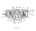
- a reel 1 having a recess groove 1-1 containing a cord 7, made from nylon or the like at its outer peripheral portion and having means (not illustrated) for fixing a central portion of the cord (when one piece of the cord is used) or one end portion thereof (when two pieces of the cords are used) and a plurality of projections 1-3 provided at equal intervals to project inwardly from inner peripheral face of a through hole 1-2 provided at the center, rotates in a case 2 constituted in the a shape of a bottomed cylinder member.
- the case 2 is provided with outlets 2-1 for leading out the cord 7 in the directions of the outer peripheral face thereof opposed to each other around the peripher, and a circular hole 2-3 is perforated at a central portion of the bottom portion 2-2.
- a hook 2-5 is provided at the edge portion of the case 2 to direct outwardly, and the hook 2-5 is constituted to be able to be engaged with a jaw portion 3-1 extended downwardly at the outer peripheral edge portion of a cover 3, able to cover over an entire face of the edge portion of the case 2. That is, by engaging the hook 2-5 with the jaw portion 3-1, the cover 3 is detachably connected to the case 2 and a housing A is constituted by the case 2 and the cover 3.
- a shaft 3-2 extended downwardly is fixed to a central portion of the cover 3 and the shaft 3-2 is provided with a screw portion 3-3 attached by screwing the shaft portion (not illustrated) of the main body of the mower.
- a plunger 4 constituted by a bottomed cylinder member fitted into the through hole 1-2 of the reel 1 and urged by a return spring 6 to project its bottom portion throush the circular hole 2-3 of the case 2, the outer peripheral face of the plunger 4 provided with a plurality of projections 4-1 projected outwardly similarly at equal intervals in correspondence with the projections 1-3 provided at the inner peripheral face of the reel 1.
- a plurality of elastic ribs 4-3 in an arm-like shape are projected from a bottom portion 4-2 of the plunger 4 in the axial direction and claw portions 4-4 provided at the free ends of the ribs 4-3 are engaged with the projected portion 3-4 in a ring-like shape provided at a lower end portion of the shaft 3-2 of the cover 3.
- the return spring 6 is expanded such that one end thereof is brought into contact with the bottom portion 4-2 of the plunger 4 to thereby urge the pressing member 4 downwardly while the other end thereof is brought into contact with the short arm portion 5-2 of an L-shaped rachet 5 axially attached rotatably to the cover 3 via a support shaft 5-1. Therefore, according to the L-shaped ratchet 5, the long arm portion 5-3 thereof is disposed in parallel with the shaft 3-2 of the cover 3 so far as centrifugal force produced by high speed rotation is not exerted to the housing A comprising the case 2 and the cover 3 (refer to Fig.
- the inner side of the cover 3 and the inner side of the case 2 are respectively provided with several projected portions 3-6 and 2-4 at equal intervals in the axial direction such that although their positions thereof can be shifted in the circumferential direction relative to the positions of the projections 4-1 of the pressing member 4 and the projections 1-3 of the reel 1, the phases are matched therewith in the axial direction. That is, the projected portions 3-6 and the projected portions 2-4 are arranged at intervals at the least larger than the widths in the circumferential direction of the projections 4-1 of the pressing member 4 or the projections 1-3 of the reel 1.
- the projection 4-1 is also lifted.
- the centrifugal force operating on the cord 7 which is rotated at low speed 4 the projections 1-3 which are brought into contact with the projections 4-1 ride over the projections 2-4 of the case 2 and brought into contact with the projections 3-6 of the cover 3 (( ⁇ ) position of Fig. 3).
- the plunger 4 is moved down and the projections 4-1 of the plunger 4 are moved further by the projections 1-3 of the reel 1 and brought into contact with the next projections 2-4 of the case 2 ((g) position of Fig. 3). That is, the reel 1 is rotated for a short period by the a distance of the interval between the projected portions 2-4 of the case 2.
- the cord 7 is reeled out from the reel 1 by a length in correspondence with a peripheral length of the interval between the projections 2-4, and when an operator strikes the plunger 4 on the protruding a desired number of times, a desired length of the cord 7 is reeled out.
- the cord 7 of the rotary cutter of the mower according to the invention is worn out and needs to be interchanged or when the rotary cutter needs to be disassembled to component parts of the inner portion for interchanging and maintenance, firstly, when the engagement between the jaw portion 3-1 of the cover 3 and the hook 2-5 of the case 2 is disengaged, the case 2 can be detached therefrom in the downward direction. Successively, the reel 1 may be detached from the plunger 4 and the cord 7 may be interchanged.
- the plunger 4 engaged with the return spring 6 and the L-shaped ratchet 5 is not separated because of the engagement between the claw portions 4-4 at the end portions of the arm-like elastic ribs 4-3 of the plunger 4 and the projected portion 3-4 in the ring-like shape of the shaft 3-2 and accordingly, reassembling is extremely facilitated. Further, in order to exchange the return spring 6 or the L-shaped ratchet 5 disposed inside of the pressing member 4, in order to release the engagement between the claw portions 4-4 and the ring-shaped projected portions 3-4, when the plunger 4 is strongly pulled down, berding the arm-like elastic ribs 4-3 in the arm-like shape, so that the pressing member 4 can be detached from the shaft 3-2.
- the plunger 4 when the plunger 4 is to be reintegrated to the shaft 3-2, after mounting the ratchet 5 and the return spring 6, when the pressing member 4 is pushed the downward side in the axial direction of the shaft 3-2, in the reverse operation of the above-described, the elastic ribs 4-3 in the arm-like shape are bent and the claw portions 4-4 are moved outward to open around the projection 3-4 in the ring-like shape and successively ride over the projected portion 3-4 and thereafter, by elasticity of the elastic ribs 4-3, the original state is recovered and the engaged state can be brought about.
- the operation of reeling out the cord when the free end of the cord is worn out can be carried out only when the rotary cutter is rotated at low speed and therefore, scattering of pebbles or the like. Further, in disengaging the rotary cutter, respective parts are not separated from each other and accordingly, there can be provided a rotary cutter for a mower which is easy to reassemble.
Landscapes
- Life Sciences & Earth Sciences (AREA)
- Environmental Sciences (AREA)
- Harvester Elements (AREA)
Claims (4)
- Rotierendes Schneidwerkzeug für einen Mäher, mit:dadurch gekennzeichnet, dasseiner Kordel (7) zum Mähen von Gras durch deren kreisende Bewegung; einer Rolle (1) zum Aufnehmen der Kordel (7) und intermittierenden Abrollen der Kordel (7) während der kreisenden Bewegung;einem Deckel (3) zum Abdecken eines die Rolle (1) enthaltenden Gehäuses (2); undeinem Stößelglied (4), das aus dem Gehäuse (2) nach unten heraus ragt und zum intermittierenden Drehen der Rolle (1) bewegbar ist, indem es in der Axialrichtung hineingedrückt wird;
eine Sperrklinke (5), die von einem Andruckmittel in einer konstanten Lage gehalten wird und von einer Zentrifugalkraft, die durch das Drehen des rotierenden Schneidwerkzeugs bei hoher Geschwindigkeit entsteht, zum Öffnen gegen das Andruckmittel ausgestreckt wird und mit dem Stößelglied (4) in Eingriff kommt, wodurch eine Bewegung des Stößelglieds (4) entlang der Axialrichtung verhindert wird. - Rotierendes Schneidwerkzeug für einen Mäher nach Anspruch 1,
bei dem das Andruckmittel eine Gegenfeder (6) zum Drücken des Stößelglieds (4) in Richtung nach außen umfasst. - Rotierendes Schneidwerkzeug für einen Mäher nach Anspruch 1 oder 2,
bei dem die Rolle (1) und das Stößelglied (4), die als getrennte Bauteile ausgebildet sind, in dem Gehäuse (2) und dem Deckel (3) untergebracht sind, die aneinander befestigbar und voneinander lösbar sind, die Rolle (1) durch Bewegen des Stößelglieds (4) in der Axialrichtung intermittierend gedreht wird und das Gehäuse (2) und die Rolle (1) von dem Stößelglied (4) getrennt werden, wenn das Gehäuse (2) und der Deckel (3) voneinander gelöst werden. - Rotierendes Schneidwerkzeug für einen Mäher nach Anspruch 3,
welches zusätzlich Eingriffsmittel umfasst, die mit einer am Hauptkörper des Mähers am mittleren Teil des Deckels (3) befestigten Welle vorgesehen sind und das Stößelglied (4) gegen die Welle halten.
Applications Claiming Priority (2)
| Application Number | Priority Date | Filing Date | Title |
|---|---|---|---|
| JP33269098 | 1998-11-24 | ||
| JP33269098A JP3982930B2 (ja) | 1998-11-24 | 1998-11-24 | 刈払機用のロータリカッタ |
Publications (3)
| Publication Number | Publication Date |
|---|---|
| EP1004232A2 EP1004232A2 (de) | 2000-05-31 |
| EP1004232A3 EP1004232A3 (de) | 2000-06-14 |
| EP1004232B1 true EP1004232B1 (de) | 2005-02-02 |
Family
ID=18257800
Family Applications (1)
| Application Number | Title | Priority Date | Filing Date |
|---|---|---|---|
| EP99122972A Expired - Lifetime EP1004232B1 (de) | 1998-11-24 | 1999-11-18 | Rotierendes Schneidewerkzeug für Mäher |
Country Status (4)
| Country | Link |
|---|---|
| US (1) | US6446345B1 (de) |
| EP (1) | EP1004232B1 (de) |
| JP (1) | JP3982930B2 (de) |
| DE (1) | DE69923525T2 (de) |
Families Citing this family (12)
| Publication number | Priority date | Publication date | Assignee | Title |
|---|---|---|---|---|
| RU2298311C2 (ru) * | 2002-06-07 | 2007-05-10 | Спид Франс | Режущий узел устройства для стрижки растений (варианты) |
| US6735874B2 (en) * | 2002-06-11 | 2004-05-18 | Kwik Products, Inc. | Cutting head for a rotary trimmer |
| JP4549301B2 (ja) * | 2006-01-10 | 2010-09-22 | ブイアイブイエンジニアリング株式会社 | 刈払機 |
| ITFI20060275A1 (it) | 2006-11-03 | 2008-05-04 | Arnetoli Motor | Testina tosaerba a filo |
| US20080168664A1 (en) * | 2007-01-17 | 2008-07-17 | Kwik Products, Inc. | Rotary trimmer head with advancing system having rounded tangs |
| US20110232106A1 (en) * | 2010-03-23 | 2011-09-29 | Desert Extrusion Corporation | Trimmer Head with Drop-Down Reservoir for Ease of Loading |
| US8656883B2 (en) | 2011-07-20 | 2014-02-25 | Briggs & Stratton Corporation | Recoil starter assembly for an engine |
| JP5959290B2 (ja) * | 2012-04-25 | 2016-08-02 | スターテング工業株式会社 | 刈払い機用ロータリカッタ |
| WO2015144197A1 (en) * | 2014-03-24 | 2015-10-01 | Husqvarna Ab | Quick loading trimmer head |
| ITUB20159496A1 (it) * | 2014-12-22 | 2017-06-16 | Arnetoli Motor Srl | Testina tosaerba a filo con lama di taglio |
| US20160183452A1 (en) | 2014-12-29 | 2016-06-30 | Husqvarna Ab | Quick loading trimmer head |
| EP4212002A4 (de) * | 2020-09-09 | 2024-08-14 | Saitou Nensi Corporation | Kabelhaltevorrichtung |
Family Cites Families (15)
| Publication number | Priority date | Publication date | Assignee | Title |
|---|---|---|---|---|
| US4211005A (en) * | 1977-07-25 | 1980-07-08 | Emerson Electric Co. | Apparatus for cutting vegetation |
| US4151646A (en) * | 1978-02-27 | 1979-05-01 | K & S Industries, Inc. | Flexible line trimmer with line feeding apparatus |
| US4185381A (en) * | 1978-07-17 | 1980-01-29 | Palmieri John P | Rotary nylon line vegetation cutter |
| JPS575608A (en) | 1980-06-14 | 1982-01-12 | Komatsu Zenoa Kk | Bush cutter |
| US4347666A (en) * | 1980-07-25 | 1982-09-07 | Emerson Electric Co. | Apparatus for cutting vegetation |
| US4412382A (en) * | 1981-05-04 | 1983-11-01 | The Toro Company | Line feed mechanism for filament cutting |
| US4426780A (en) * | 1981-09-03 | 1984-01-24 | The Toro Company | Line metering apparatus |
| DE3503237A1 (de) * | 1985-01-31 | 1986-08-07 | Fa. Andreas Stihl, 7050 Waiblingen | Schneidkopf |
| DE3739268A1 (de) * | 1987-11-20 | 1989-06-01 | Stihl Maschf Andreas | Schneidkopf |
| DE3922339C1 (de) * | 1989-07-07 | 1990-10-18 | Fa. Andreas Stihl, 7050 Waiblingen, De | |
| US5020223A (en) * | 1989-11-02 | 1991-06-04 | White Consolidated Industries, Inc. | Simplified bump-feed type cutting head assembly for flexible line trimmers |
| US5311665A (en) * | 1990-11-16 | 1994-05-17 | Diatop Corporation | Cutting head for a cord type mower |
| JP3113270B2 (ja) * | 1990-11-16 | 2000-11-27 | 杉原林機株式会社 | コード型草刈機の刈刃装置におけるコード繰出し機構 |
| AU1499495A (en) * | 1994-04-08 | 1995-10-19 | Wci Outdoor Products, Inc. | Line head for flexible line trimmer |
| US5906051A (en) * | 1998-04-03 | 1999-05-25 | Nannen; William G. | Height adjustable anti-gouging ground guide system for vegetation trimmer |
-
1998
- 1998-11-24 JP JP33269098A patent/JP3982930B2/ja not_active Expired - Lifetime
-
1999
- 1999-11-18 DE DE69923525T patent/DE69923525T2/de not_active Expired - Lifetime
- 1999-11-18 EP EP99122972A patent/EP1004232B1/de not_active Expired - Lifetime
- 1999-11-22 US US09/444,839 patent/US6446345B1/en not_active Expired - Lifetime
Also Published As
| Publication number | Publication date |
|---|---|
| US6446345B1 (en) | 2002-09-10 |
| JP3982930B2 (ja) | 2007-09-26 |
| EP1004232A2 (de) | 2000-05-31 |
| JP2000157028A (ja) | 2000-06-13 |
| DE69923525D1 (de) | 2005-03-10 |
| EP1004232A3 (de) | 2000-06-14 |
| DE69923525T2 (de) | 2006-01-12 |
Similar Documents
| Publication | Publication Date | Title |
|---|---|---|
| EP1004232B1 (de) | Rotierendes Schneidewerkzeug für Mäher | |
| CN113575170B (zh) | 打草头和打草机 | |
| CA2464857C (en) | Fixed line head for flexible line rotary trimmers | |
| US4412382A (en) | Line feed mechanism for filament cutting | |
| US4672798A (en) | Apparatus for cutting grass | |
| EP1670305B1 (de) | Schneidkopf zur verwendung in drehtrimmern von flexiblem schneidfaden | |
| EP2319288B1 (de) | Fadenkopf für einen Trimmer | |
| US6418627B1 (en) | Rotary cutter of mower | |
| CN105815028B (zh) | 打草机及打草机的放线方法 | |
| EP0168254A2 (de) | Schnurmäher zum Schneiden von Pflanzen | |
| US4524515A (en) | Rotary cutting assembly with filament feed | |
| US4738085A (en) | Rotary cutter for mowers | |
| US4245454A (en) | Line metering apparatus | |
| US4176508A (en) | Line feed mechanism for filament mower | |
| EP0271762B1 (de) | Mittel zum Zuführen des Fadens für Fadenschneidkopf | |
| JP2007312769A (ja) | 刈払い機用ロータリカッタ | |
| US4131997A (en) | Vegetation cutting apparatus having a semiautomatically dispensed flexible line cutting element | |
| JP2818744B2 (ja) | コード式草刈り機のコード長調整装置 | |
| CA1212552A (en) | Rotary cutting assembly with filament feed | |
| CA1111257A (en) | Flexible line trimmer with line feeding apparatus |
Legal Events
| Date | Code | Title | Description |
|---|---|---|---|
| PUAI | Public reference made under article 153(3) epc to a published international application that has entered the european phase |
Free format text: ORIGINAL CODE: 0009012 |
|
| PUAL | Search report despatched |
Free format text: ORIGINAL CODE: 0009013 |
|
| 17P | Request for examination filed |
Effective date: 19991217 |
|
| AK | Designated contracting states |
Kind code of ref document: A2 Designated state(s): DE GB IT SE |
|
| AX | Request for extension of the european patent |
Free format text: AL;LT;LV;MK;RO;SI |
|
| AK | Designated contracting states |
Kind code of ref document: A3 Designated state(s): AT BE CH CY DE DK ES FI FR GB GR IE IT LI LU MC NL PT SE |
|
| AX | Request for extension of the european patent |
Free format text: AL;LT;LV;MK;RO;SI |
|
| AKX | Designation fees paid |
Free format text: DE GB IT SE |
|
| 17Q | First examination report despatched |
Effective date: 20021118 |
|
| GRAP | Despatch of communication of intention to grant a patent |
Free format text: ORIGINAL CODE: EPIDOSNIGR1 |
|
| GRAS | Grant fee paid |
Free format text: ORIGINAL CODE: EPIDOSNIGR3 |
|
| GRAA | (expected) grant |
Free format text: ORIGINAL CODE: 0009210 |
|
| AK | Designated contracting states |
Kind code of ref document: B1 Designated state(s): DE GB IT SE |
|
| REG | Reference to a national code |
Ref country code: GB Ref legal event code: FG4D |
|
| REF | Corresponds to: |
Ref document number: 69923525 Country of ref document: DE Date of ref document: 20050310 Kind code of ref document: P |
|
| REG | Reference to a national code |
Ref country code: SE Ref legal event code: TRGR |
|
| PLBE | No opposition filed within time limit |
Free format text: ORIGINAL CODE: 0009261 |
|
| 26N | No opposition filed |
Effective date: 20051103 |
|
| PGFP | Annual fee paid to national office [announced via postgrant information from national office to epo] |
Ref country code: SE Payment date: 20181126 Year of fee payment: 20 Ref country code: DE Payment date: 20181128 Year of fee payment: 20 |
|
| PGFP | Annual fee paid to national office [announced via postgrant information from national office to epo] |
Ref country code: GB Payment date: 20181126 Year of fee payment: 20 Ref country code: IT Payment date: 20181122 Year of fee payment: 20 |
|
| REG | Reference to a national code |
Ref country code: DE Ref legal event code: R071 Ref document number: 69923525 Country of ref document: DE |
|
| REG | Reference to a national code |
Ref country code: GB Ref legal event code: PE20 Expiry date: 20191117 |
|
| PG25 | Lapsed in a contracting state [announced via postgrant information from national office to epo] |
Ref country code: GB Free format text: LAPSE BECAUSE OF EXPIRATION OF PROTECTION Effective date: 20191117 |
|
| REG | Reference to a national code |
Ref country code: SE Ref legal event code: EUG |