EP1004233B1 - Tragbare landwirtschaftliche, vibrierende, sammelnde maschine - Google Patents
Tragbare landwirtschaftliche, vibrierende, sammelnde maschine Download PDFInfo
- Publication number
- EP1004233B1 EP1004233B1 EP98928349A EP98928349A EP1004233B1 EP 1004233 B1 EP1004233 B1 EP 1004233B1 EP 98928349 A EP98928349 A EP 98928349A EP 98928349 A EP98928349 A EP 98928349A EP 1004233 B1 EP1004233 B1 EP 1004233B1
- Authority
- EP
- European Patent Office
- Prior art keywords
- engine
- rod
- frame
- machine according
- parts
- Prior art date
- Legal status (The legal status is an assumption and is not a legal conclusion. Google has not performed a legal analysis and makes no representation as to the accuracy of the status listed.)
- Expired - Lifetime
Links
- 238000003306 harvesting Methods 0.000 claims abstract description 9
- 235000013399 edible fruits Nutrition 0.000 claims abstract description 8
- 230000000694 effects Effects 0.000 claims abstract description 8
- 241000207836 Olea <angiosperm> Species 0.000 claims abstract description 3
- 241000220304 Prunus dulcis Species 0.000 claims abstract description 3
- 235000020224 almond Nutrition 0.000 claims abstract description 3
- 230000007246 mechanism Effects 0.000 claims description 22
- 210000000056 organ Anatomy 0.000 claims description 12
- 230000008878 coupling Effects 0.000 claims description 5
- 238000010168 coupling process Methods 0.000 claims description 5
- 238000005859 coupling reaction Methods 0.000 claims description 5
- 230000010355 oscillation Effects 0.000 claims description 5
- 239000007858 starting material Substances 0.000 claims description 4
- 239000000463 material Substances 0.000 claims description 3
- 230000002787 reinforcement Effects 0.000 claims description 3
- 230000000717 retained effect Effects 0.000 claims description 3
- 239000002828 fuel tank Substances 0.000 claims description 2
- 238000003466 welding Methods 0.000 claims description 2
- 238000013138 pruning Methods 0.000 description 4
- 238000006243 chemical reaction Methods 0.000 description 3
- 230000006378 damage Effects 0.000 description 3
- 206010044565 Tremor Diseases 0.000 description 1
- 238000005452 bending Methods 0.000 description 1
- 206010016256 fatigue Diseases 0.000 description 1
- 230000003472 neutralizing effect Effects 0.000 description 1
- 230000003014 reinforcing effect Effects 0.000 description 1
- 238000010008 shearing Methods 0.000 description 1
- 230000002459 sustained effect Effects 0.000 description 1
Images


Classifications
-
- A—HUMAN NECESSITIES
- A01—AGRICULTURE; FORESTRY; ANIMAL HUSBANDRY; HUNTING; TRAPPING; FISHING
- A01D—HARVESTING; MOWING
- A01D46/00—Picking of fruits, vegetables, hops, or the like; Devices for shaking trees or shrubs
- A01D46/26—Devices for shaking trees or shrubs; Fruit catching devices to be used therewith
- A01D2046/266—Portable devices to shake branches
Definitions
- This patent relates to a tree fruit vibrating-harvesting portable agricultural machine, of those designed to harvest fruits such as olives or almonds, which are picked from the trees by applying on a tree branch or secondary trunk a linear alternative or vibrating motion produced by a vibration generating mechanism, already known, engine driven and transmitted by means of a rod bearing at its end an element catching said branch/secondary trunk.
- the invention applies to above type machines, portable and with motive means of their own in order to be able to be carried out their work at places where there is no related motive power or lighting outlet available.
- Most of the means this invention is proposing are also applicable to other machines mainly agricultural machines, provided with a tool associated to a rod end, for example pruning devices by means of a saw for medium-sized branches located at a very high place, scissors for green and high small branches pruning or machines equipped with a tool attached to the frame itself , such as scissors for pruning low and small branches, knife mowing machines, punch presses, etc., whose operation transmits a reactive oscillation or shake (because of the higher tree mass on which they are acting with respect to the machine) to the assembly to which the engine is coupled.
- pruning devices by means of a saw for medium-sized branches located at a very high place, scissors for green and high small branches pruning or machines equipped with a tool attached to the frame itself , such as scissors for pruning low and small branches, knife mowing machines, punch presses, etc., whose operation transmits a reactive oscillation or shake (because of the higher tree mass on which they are acting with respect to the machine) to the assembly to which the engine is coupled.
- US-A-4,873,820 discloses a machine of the above type, wherein an articulation unit is included serving to connect the cited rod with a vibration transmitting element.
- Said articulation unit comprises a ball and socket attached to a connecting-rod of the vibration generating mechanism and linked to a forked end of the rod by means of a bolt, a needle cage being provided between said socket and said bolt.
- said bolt is not designed to break or fail upon eventual overstresses higher than normal stresses produced by vibrating operation of the machine.
- said articulation unite does not allow the rod free rotation in both directions about its axis.
- All those machines are characterized in that they have available a main frame which houses said vibrating motion generating mechanism (for example, a connecting rod-crank unit), driven by a standard two- or four-stroke-cycle heat engine and a long guided rod or pole, bearing at its end farthest from the machine an element for catching the tree branch or secondary trunk, said rod being in addition the one which transmits the vibrating motion from the generating mechanism up to the catching element.
- said vibrating motion generated by this type of mechanisms is a relatively high frequency alternating linear motion.
- a problem which arises with this type of machines is that, because of the very nature of the function they have to perform, they sustain strong vibrations and occasionally bouncings (sharp stress in an undetermined, lengthwise or twisted direction with further back motion and repeating it), which are transmitted to the operator who is operating them affecting him in several ways. While the phenomenon of vibrations appears in a continuous and relatively regular way, provoking an effect of early fatigue to the operator, the phenomenon of bouncings occurs in an unexpected and occasionally violent manner and it can provoke differently serious injuries to the operator, as well as damages in the machine organs.
- the invention seeks to overcome said problems by proposing for such purpose means that, on one hand provide a great strength to the engine junction to the machine frame as well as other means to achieve a connection or coupling between the rod, bearing the catching member at its free end and the vibrating mechanism or to a part connected to said mechanism which makes possible that said rod rotates or is occasionally broken when it exceeds a certain overstress.
- the invention relates to a tree fruit vibrating-harvesting portable agricultural machine according to claim 1,
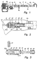
- a vibrating-harvesting portable agricultural machine which includes an already known vibration generating mechanism 1, driven by an engine 2 and transmitted through a rod 33 bearing at its end a catching member 4.
- Said catching member 4 has the function to hold a tree branch or secondary trunk to transmit it the vibrations generated by the machine in order to have the fruits they contain drop.
- Said machine is characterized in that it comprises means for neutralizing the vibration effect and occasional bouncings on the rod 3 and on a part joining the engine 2 to a machine frame 6, which comprises: a junction fixture 5 which keeps an end of said rod 3 distal from the member 4, or a part 3a extension thereof, connected to the vibration mechanism transmitting element 1a and which allows that said rod 3 freely rotates in both directions, about its axis; a connecting organ 7, 7a which has available a first 8 and a second 9 parts integral respectively with a first 3a and a second 3b segments of said rod 3, or respectively with said rod 3 and with a connecting element to the vibration generating mechanism 1, which may be inserted between them socketed retained by a removable locking member, through a retaining element 11, made of a material which may be broken when sustaining overstresses exceeding a predetermined value or threshold; and an auxiliary frame 20 surrounding the engine 2 with at least a front part 21, coupled to the engine 2 by a first face, a back part 22 coupled by a second face, opposite
- said junction fixture 5 is located within the machine main frame 6 at a point located between the vibration alternate linear motion generating mechanism 1 and an internal linearly guided portion of a rod 3a which transmits said alternate linear motion, said rod 3a being connected by its external portion said rod end 3 distal from the catching element 4.
- Said fixture 5 comprises an axial part or core 30 provided close to one of its ends with a collar 31 and whose other end has a junction element 32 to coaxially lock said core 30 with the end of said rod 3 internal portion 3a, said core 30 is arranged inserted together with two axial bearings 33, one to each of the sides of said collar 31, within a housing 34 located at one end of a body 35, said housing 34 having available a threaded portion 34a close to its mouthpiece, provided to receive an externally threaded sleeve 36 screwed which is coupled coaxially embedded on the core 30, acting as retaining part for the collar 31 between the two bearings 33, the body 35 having available at its opposite end, a fork-shaped portion 35a with a through hole 36 perpendicular to its lengthwise axis for mounting a bolt 37 for its junction with the vibration alternate linear motion generating mechanism 1.
- Said fork-shaped portion 35a with a through hole 36 perpendicular to its lengthwise axis for mounting a bolt 37 is joined, through a radial bearing 38 to a connecting rod head 1a which is comprised in a vibration alternate linear motion generating connecting-rod-crank mechanism.
- said junction fixture 50 is located external the machine main frame 6 and comprises an axial part 51 provided close to a collar 52 or rim first end at a certain distance from a second end of a portion 53 for a screwed junction or other mechanical locking means, with the rod end 3 distal from the catching member 4 coaxially coupled on said threaded portion 53, whose axial part 51 is arranged inserted within a tubular body 54, with a drinking-glass-shaped enlarged portion 54a which may house the collar 52 on its bottom, said portion 54a being internally threaded to receive socketed to its mouthpiece an externally threaded sleeve 55, which is coaxially coupled on the axial part 51, its threaded portion 53 outwardly protruding through it to catch said collar 52 within the drinking-glass-shaped body 54a with prior arrangement on each of said collar 52 faces of a needle bearing 56 and in that said tubular part 54 possesses a portion 54b fillet profiled for its junction to a
- said portion 53 is threaded.
- an external housing 70 has also been provided as a liner which protects the rod 3 initial section likewise covering the junction fixture 50 or connecting organ 7, 7 a allowing that the operator catches it with one hand without any risk of damages for him.
- referred locking member is constituted by a sleeve (10) and said retaining element consists in a ring (11) which is housed in a lesser spanned junction part (9) groove (9c).
- Coupling between the first and second junction parts (8, 9) is a conical link comprising one of the junction parts (9) male part (9a) which is arranged inserted within another female part (8a) of the other junction part (8), said two junction parts (8,9) have available extensions for permanent or removable junction with the rod (3) segments (3a, 3b) or a vibration transmitting element and a rod (3) end distal from the catching hook (4).
- said first junction part (8) is provided at one of its ends with an external fillet (8b) which may be screwed in an internal related fillet at the first segment (3a) end said first junction part (8) having available at its other larger diameter end a female frustum-shaped recess (8a) coaxial and having an external fillet (8c) and in that said second junction part (9) is provided , at one of its ends, with an internal cylindric hole (9b) which may be pressure bond or screwed at a related end of the rod (3) second segment (3b), said second junction part (9) having at its other end a male frustum-shaped protrusion (9a) coaxial, with a conicity identical to that of the female recess (8a) and which may be inserted in it, said second junction part (9) having available a cylindrical central area provided with two annular grooves (9c, 9d) in the former of which said retaining ring (11) is inserted and in the second of which another retaining
- the ring (12) remains housed in a groove (9d) of the junction part (9) and located external the sleeve (10), when this later acts linking said parts (8, 9) so that said ring (12) constitutes a stop, which actively assists the release between the two parts (8, 9) when unscrewing the sleeve (10).
- said connecting organ (7a) comprises a part (40) which may be socketed by one of its ends with the first segment (3a) end or an auxiliary part (41) integral with it and whose other end is prepared to be joined to the beginning of the second segment (3b) or an auxiliary part (42) which extends it, said junction part (40) having available a bevel (43) cooperating with a related bevel (44) of the end of the second segment (3b) or the reinforcing part (42) to form a seat groove for the internal part of an annular retaining element (45), protecting against overstresses.
- said locking member is constituted by a sleeve (46) prepared to be joined by one of its ends with the end of the first segment (3a) or the auxiliary part (41) and provided at its other end with an internal groove (46a) for housing the external part of said annular retaining element (45).
- the fit between the part (40) and the first segment (3a) or the auxiliary part (4) end is a conical fit which comprises part (40) male part (40a) which is arranged inserted within first segment (3a) or the auxiliary part (41) end female part (41a).
- the junction between the locking sleeve (46) and the auxiliary part (41) may be a screwed junction or a bayonet attachment.
- junction between the junction part (40) and the second segment (3b) end or the reinforcement part (42) is carried out according to a screwed junction or a bayonet attachment.
- the annular retaining element (45) remains locked between the groove formed by the two bevels (43 and 44) and the internal groove (46a) of the fastening sleeve (46), said sleeve (46) being rotatably linked with the parts (40 and 3a or 40 and 41) so that said sleeve (46) acts linking the parts (40 and 3a or 40 and 41) when screwed and actively assists to release the conical fit between the parts (40 and 3a or 40 and 41) when unscrewed so that the groove (46) will provoke a ring (45) shearing in the event a predetermined stress threshold is exceeded, the rod two segments (3a) and (3b) remaining loosened.
- said auxiliary frame comprises means which wraps the engine and the auxiliary parts assembly which constitute a reinforcement subframe 20 with at least a front part 21 and a rear part 22 applied against the front and back portions of said assembly and joined to each other under the tension of tensions elements 23, 24, said subframe 20 being linked through said front part 21 to a machine main frame 6 which houses a mechanism to transmit a suitable motion to the working tool.
- said subframe 20 basically comprises a front part 21 which is generally applied against the assembly clutch block 25, said part 21 being provided with a central part to which is linked the engine frame 2 by means of screws, flanges, welding or other system, and from which are protruding one or several brackets whose ends are joined by means of higher 23 and lower 24 tension members to another part which locks the engine by the rear part.
- Said tension members 23, 24 are joined at their front part, in addition to the front part 21 which packs the assembly, to the main frame 6 rear end.
- Said subframe 20 front part 21 may be constituted by a portion which is an extension of the main frame 6 rear part.
- said subframe 20 front part 21 is constituted by an independent part provided with a portion for coupling to the main frame 6 end to which it is tightly joined by already known junction means.
- the rear part 22 includes an annular portion which comprises the engine 2 starter 26 and has available a hole through which the starter 27 is arranged, which is protruding from said annular part, radial arms starting from it which at their ends are joined to said tension members 23, 24.
- Said rear part 22 is screwed on the engine frame 2.
- the rear part 22 remains applied against the engine 2 rear face with the interposition of a resilient element between the part and the engine (not shown), compressed under the tension pressure of the junction tension members 23, 24 of the front part 21 and rear part 22 to the engine.
- the span of said subframe 20 front 21 and rear 22 parts is such that it determines the engine 2 and auxiliary parts protecting wrapping preventing they can receive an occasional impact on their critical parts such as carburettor, exhaust pipe, sparking plug, fuel tank or others as well to the part suitably covered by said wrapping as to its sides.
- junction tension members 23, 24 are arranged covering the engine 2 and auxiliary parts assembly sides.
Landscapes
- Life Sciences & Earth Sciences (AREA)
- Environmental Sciences (AREA)
- Harvester Elements (AREA)
- Catching Or Destruction (AREA)
- Harvesting Machines For Specific Crops (AREA)
- Soil Working Implements (AREA)
- Apparatuses For Bulk Treatment Of Fruits And Vegetables And Apparatuses For Preparing Feeds (AREA)
Claims (14)
- Tragbares Landwirtschaftsgerät zum Schütteln und Ernten von Baumobst, das zum Ernten von Obst wie z.B. Oliven oder Mandeln vorgesehen ist, die von den Bäumen dadurch gepflückt werden, dass man an einem Baumast oder Nebenstamm eine lineare Wechsel- oder Schwingungsbewegung durchführt, die durch einen schwingungserzeugenden Mechanismus (1) erfolgt, der von einem Motor (2) angetrieben und mittels einer Stange (3) übertragen wird, die an ihrem Ende ein Glied (4) trägt, das den Ast/Nebenstamm greift, dadurch gekennzeichnet, dass sie Mittel aufweist, mit denen die Wirkung des Schüttelns und des gelegentlichen Zurückprallens von einem Verbindungsstück des Motors (2) mit dem Geräterahmen (6) neutralisiert wird, mit einem Hilfsrahmen (20), der den Motor (2) zumindest mit einem vorderen Teil (21) umgibt, der an eine die Hauptwelle umgebende Fläche des Motors (2) gekoppelt ist, wobei ein rückwärtiger Teil (22) an eine zweite, der ersten Fläche gegenüberliegende Fläche gekoppelt ist, sowie mindestens zwei Spannelementen (23, 24), die an ihren Enden mit dem vorderen (21) und rückwärtigen Teil (22) verbunden sind, und zwar an mindestens zwei gegenüberliegenden Seiten, wobei die gegebenenfalls gestreckten Spannelemente (23, 24) parallel zur Richtung der linearen Wechsel- bzw. Schwingungsbewegung wirken, wobei sie den Motor (2) einschließen und in dieser Richtung zusammendrücken, wobei dessen Hilfsrahmen (20) mit dem rückwärtigen Ende des Gerätehauptrahmens (6) verbunden ist.
- Gerät nach Anspruch 1, dadurch gekennzeichnet, dass der Hilfsrahmen (20) Mittel aufweist, durch die der Motor und der Hilfsteilaufbau umhüllt wird, die einen Verstärkungsunterrahmen (20) darstellen darstellen mit mindestens einem Vorderteil (21) und einem Rückteil (22), die an dem Vorder- und Rückteil des Aufbaus anliegen und unter der Spannung der Spannelemente (23, 24) miteinander verbunden sind, wobei der Unterahmen (20) über das Vorderteil (21) mit einem Geräterahmen (6) verbunden ist, in dem ein Mechanismus zur Übertragung einer geeigneten Bewegung auf das Arbeitswerkzeug untergebracht ist.
- Gerät nach Anspruch 2, dadurch gekennzeichnet, dass der Unterrahmen (20) grundsätzlich ein Vorderteil (21) aufweist, das im allgemeinen am Kupplungsblock (25) des Aufbaus anliegt, wobei das Teil (21) einen Mittelteil aufweist, an dem der Motorrahmen (2) mit Schrauben, Flanschen, durch Verschweißen oder auf andere Weise befestigt ist und über den ein oder mehrere Klammern vorstehen, deren Enden durch höherliegende (23) und niedrigerliegende (24) Spannelemente mit einem anderen Teil verbunden sind, das die Maschine an der Rückseite verschließt.
- Gerät nach Anspruch 2 oder 3, dadurch gekennzeichnet, dass das Vorderteil (21) des Unterrahmens (20) aus einem Abschnitt besteht, der eine Verlängerung des Rückteils des Hauptrahmens (6) darstellt.
- Gerät nach Anspruch 2 oder 3, dadurch gekennzeichnet, dass das Vorderteil (21) des Unterrahmens (20) aus einem unabhängigen Abschnitt besteht, der mit einem Abschnitt zum Ankoppeln an das Ende des Hauptrahmens (6) versehen ist, mit dem dieser mittels bereits bekannter Verbindungsmittel dicht verbunden ist.
- Gerät nach Anspruch 2, dadurch gekennzeichnet, dass das Rückteil (22) einen ringförmigen Abschnitt mit dem Starter (26) des Motors (2) und eine Bohrung, durch die der Starter (27), der über das ringförmige Teil hinausragt, sowie dort beginnende radiale Arme aufweist, die an ihren Enden mit den Spannelementen (23, 24) verbunden sind.
- Gerät nach Anspruch 2, dadurch gekennzeichnet, dass das Rückteil (22) am Motorrahmen (2) angeschraubt ist.
- Gerät nach Anspruch 3, dadurch gekennzeichnet, dass das Rückteil (22) stets an der Rückfläche des Motors (2) anliegt, wobei zwischen dem Teil und dem Motor ein elastisches Element zwischengeschaltet ist, das unter dem Spanndruck der Verbindungsspannelemente (23, 24) des Vorderteils (21) und Rückteils (22) des Motors (2) zusammengedrückt wird.
- Gerät nach Anspruch 5, dadurch gekennzeichnet, dass die Spannelemente (23, 24) mit dessen Vorderteil (21) verbunden sind, durch das der Aufbau am rückwärtigen Ende des Hauptrahmens (6) befestigt wird.
- Gerät nach Anspruch 3, dadurch gekennzeichnet, dass die Öffnungsweite zwischen dem Vorderteil (21) und dem Rückteil (22) des Unterrahmens (20) so bemessen ist, dass hierdurch eine Schutzumhüllung des Motors (2) und der Hilfsteile bestimmt wird, durch die verhindert wird, dass kritische Teile wie Vergaser, Auspuffrohr, Zündkerze, Benzintank oder auch andere Teile sowie die von der Verpackung abgedeckten Teile, wie z.B. Seiten, gelegentlich einer Schlagwirkung ausgesetzt sind.
- Gerät nach Anspruch 2, dadurch gekennzeichnet, dass die Verbindungsspannelemente (23, 24) so angeordnet sind, dass sie den Motor (2) und die Seiten des Hilfsteilaufbau abdecken.
- Gerät nach Anspruch 1, das weiterhin Mittel umfasst, durch die das Halten/Greifen eines Astes bzw. Nebenstamms erleichtert und somit die Wirkung eines gelegentlichem Abprallens von der Stange (3) neutralisiert wird, mit einer Verbindungshalterung (5, 50), durch das vom Element (4) entfernt liegende Ende der Stange (3) oder dessen teilweise Verlängerung (3a) mit dem den Schwingungsmechanismus übertragenden Element (1a) in Verbindung gehalten wird, wodurch eine freie Drehung der Stange (3) in beiden Richtungen um ihre Längsachse ermöglicht wird.
- Gerät nach Anspruch 1, das weiterhin Mittel zur Begrenzung von Überbeanspruchungen umfasst, durch die die nachteilige Wirkung von Schwingungen und gelegentlichem Abprallen von der Stange (3) ausgeglichen wird, mit einem Verbindungsorgan (7, 7a) mit einem ersten (8) und einem zweiten (9) Teil, die zusammen mit dem ersten (3a) bzw. zweiten (3b) Abschnitt der Stange (3) ein einziges Stück bilden oder daran befestigt sind, wobei das erste (8) und zweite (9) Teil miteinander eine koppelnde Passung bilden und durch ein lösbares Sperrglied (10) zusammengehalten werden, das durch ein Halteelement (11) aus einem Material unterstützt wird, das beim Aushalten einer Überbeanspruchung über einen vorgegebenen Wert oder eine vorgegebene Schwelle Bruch erleidet.
- Gerät nach Anspruch 1, weiterhin umfassend:eine Verbindungshalterung (5), die das von dem Element (4) entfernt liegende Ende der Stange (3) oder dessen teilweise Verlängerung (3a) mit dem den Schwingungsmechanismus übertragenden Element (1a) in Verbindung gehalten wird, wodurch eine freie Drehung der Stange (3) in beiden Richtungen um ihre Längsachse ermöglicht wird; sowieein Verbindungsorgan (7, 7a) mit einem ersten (8) und einem zweiten (9) Teil, die zusammen mit dem ersten (3a) bzw. zweiten (3b) Abschnitt der Stange (3) ein einziges Stück bilden oder daran befestigt sind, wobei das erste (8) und zweite (9) Teil miteinander eine koppelnde Passung bilden und durch ein lösbares Sperrglied (10) zusammengehalten werden, das durch ein Halteelement (11) aus einem Material unterstützt wird, das beim Aushalten einer Überbeanspruchung über einen vorgegebenen Wert oder eine vorgegebene Schwelle Bruch erleidet.
Applications Claiming Priority (11)
| Application Number | Priority Date | Filing Date | Title |
|---|---|---|---|
| ES9701499A ES2152776B1 (es) | 1997-06-30 | 1997-06-30 | Sistema de sujecion de motores para maquinas agricolas, portatiles, sometidas a oscilacion-vibracion. |
| ES9701499 | 1997-06-30 | ||
| ES9702281U | 1997-09-01 | ||
| ES9702281U ES1038129Y (es) | 1997-09-01 | 1997-09-01 | Accesorio para empalme de una vara de sujecion de las ramas a una maquina vibradora-recolectora. |
| ES9800454U ES1039383Y (es) | 1998-02-17 | 1998-02-17 | Accesorio para empalme de una vara de sujecion de las ramas, a una maquina vibradora-recolectora. |
| ES9800454U | 1998-02-17 | ||
| ES9800497U | 1998-02-20 | ||
| ES9800497U ES1039539Y (es) | 1998-02-20 | 1998-02-20 | Dispositivo de conexion, con protector de sobreesfuerzos, para maquina agricola vibradora-recolectora. |
| ES9800852U | 1998-03-30 | ||
| ES9800852U ES1039793Y (es) | 1998-03-30 | 1998-03-30 | Dispositivo de union, con protector de sobreesfuerzos, para maquina agricola vibradora-recolectora. |
| PCT/ES1998/000190 WO1999001022A1 (es) | 1997-06-30 | 1998-06-30 | Maquina agricola portatil, vibradora-recolectora |
Publications (2)
| Publication Number | Publication Date |
|---|---|
| EP1004233A1 EP1004233A1 (de) | 2000-05-31 |
| EP1004233B1 true EP1004233B1 (de) | 2003-07-30 |
Family
ID=27514553
Family Applications (1)
| Application Number | Title | Priority Date | Filing Date |
|---|---|---|---|
| EP98928349A Expired - Lifetime EP1004233B1 (de) | 1997-06-30 | 1998-06-30 | Tragbare landwirtschaftliche, vibrierende, sammelnde maschine |
Country Status (8)
| Country | Link |
|---|---|
| EP (1) | EP1004233B1 (de) |
| AT (1) | ATE245889T1 (de) |
| AU (1) | AU8021998A (de) |
| DE (1) | DE69816826T2 (de) |
| ES (1) | ES2205505T3 (de) |
| PT (1) | PT1004233E (de) |
| TR (1) | TR200000307T2 (de) |
| WO (1) | WO1999001022A1 (de) |
Cited By (1)
| Publication number | Priority date | Publication date | Assignee | Title |
|---|---|---|---|---|
| EP2008506A1 (de) | 2007-06-27 | 2008-12-31 | Andreas Stihl AG & Co. KG | Handgeführtes Arbeitsgerät |
Families Citing this family (8)
| Publication number | Priority date | Publication date | Assignee | Title |
|---|---|---|---|---|
| US6716086B1 (en) | 1999-06-14 | 2004-04-06 | Applied Materials Inc. | Edge contact loadcup |
| ES2197731B1 (es) * | 1999-12-16 | 2005-03-16 | Cifarelli S.P.A. | Junta de conexion para la transmision de fuerzas axiales entre organos mecanicos dispuestos en sucesion, en particular para dispositivos sacudidores de plantas. |
| US7101253B2 (en) | 2002-08-27 | 2006-09-05 | Applied Materials Inc. | Load cup for chemical mechanical polishing |
| ITBO20030599A1 (it) * | 2003-10-14 | 2005-04-15 | Campagnola Srl | Dispositivo scuotitore portatile. |
| ES2606183T3 (es) | 2013-07-23 | 2017-03-23 | Mehmet Celik | Máquina cosechadora para oliva y frutas similares con frecuencia de vibración de resonancia de fruta ajustable |
| CN109601134A (zh) * | 2019-01-21 | 2019-04-12 | 西安航空职业技术学院 | 一种摇树振动机构 |
| EP4090150B1 (de) * | 2020-01-15 | 2025-12-03 | Cifarelli S.p.A. | Verbesserte verbindung für maschinenkomponenten und tragbare schüttelmaschine mit einer solchen verbindung |
| CN115211345A (zh) * | 2022-08-29 | 2022-10-21 | 湖南省棉花科学研究所 | 一种百合珠芽快速繁殖育苗技术及采收装置 |
Family Cites Families (14)
| Publication number | Priority date | Publication date | Assignee | Title |
|---|---|---|---|---|
| US3457713A (en) * | 1966-10-28 | 1969-07-29 | Charles E Plummer | Tree shaking device |
| US3459269A (en) * | 1967-05-25 | 1969-08-05 | Textron Inc | Fruit harvester |
| US3696597A (en) * | 1971-04-16 | 1972-10-10 | Spencer B Sitter | Resilient linkage for limb shaker |
| US3924390A (en) * | 1974-06-07 | 1975-12-09 | Wells Mfg Corp | Portable power-driven harvesting implement |
| BR5500722U (pt) * | 1975-04-03 | 1977-02-23 | Hatsuta Brasil | Aperfeicoamento em maquina portatil para colher graos de cafe |
| US4759128A (en) * | 1986-02-13 | 1988-07-26 | Komatsu Zenoah Co. | Transmission device |
| ES1000253Y (es) * | 1986-12-10 | 1988-06-01 | Martorell Puig Aurelio Tomas | Dispositivo vibrador para producir la caida de los frutos de los arboles |
| FR2639175B1 (fr) * | 1988-12-06 | 1991-07-26 | Geiver Sa | Appareil vibrateur portatif pour la recolte des fruits |
| ES2021986A6 (es) * | 1990-03-20 | 1991-11-16 | Gurri Molins Josep | Perfeccionamientos en los aparatos para el vareo mecanico de arboles frutales y de bayas. |
| ES1015565Y (es) * | 1990-10-08 | 1992-01-16 | Fornos Gimeno Domingo | Maquina portatil perfeccionada multiuso. |
| ES1020705Y (es) * | 1992-03-13 | 1993-03-16 | Fornos Gimeno Domingo | Maquina portatil perfeccionada multiuso. |
| ES1026776Y (es) * | 1993-12-29 | 1994-12-01 | Prosehinco S A | Dispositivo para la fijacion de una vara vibradora al correspondiente organo de accionamiento. |
| ES1031113Y (es) * | 1995-05-18 | 1996-12-01 | Montoro Rafael Herrera | Vibrador para la recoleccion de frutos. |
| ES1032630Y (es) * | 1995-12-01 | 1996-10-16 | Geimeno Domingo Fornos | Maquina portatil perfeccionada multiuso. |
-
1998
- 1998-06-30 PT PT98928349T patent/PT1004233E/pt unknown
- 1998-06-30 AU AU80219/98A patent/AU8021998A/en not_active Abandoned
- 1998-06-30 EP EP98928349A patent/EP1004233B1/de not_active Expired - Lifetime
- 1998-06-30 WO PCT/ES1998/000190 patent/WO1999001022A1/es not_active Ceased
- 1998-06-30 ES ES98928349T patent/ES2205505T3/es not_active Expired - Lifetime
- 1998-06-30 TR TR2000/00307T patent/TR200000307T2/xx unknown
- 1998-06-30 AT AT98928349T patent/ATE245889T1/de not_active IP Right Cessation
- 1998-06-30 DE DE69816826T patent/DE69816826T2/de not_active Expired - Fee Related
Cited By (2)
| Publication number | Priority date | Publication date | Assignee | Title |
|---|---|---|---|---|
| EP2008506A1 (de) | 2007-06-27 | 2008-12-31 | Andreas Stihl AG & Co. KG | Handgeführtes Arbeitsgerät |
| DE102007029616A1 (de) | 2007-06-27 | 2009-01-08 | Andreas Stihl Ag & Co. Kg | Handgeführtes Arbeitsgerät |
Also Published As
| Publication number | Publication date |
|---|---|
| ATE245889T1 (de) | 2003-08-15 |
| EP1004233A1 (de) | 2000-05-31 |
| DE69816826D1 (de) | 2003-09-04 |
| TR200000307T2 (tr) | 2000-07-21 |
| WO1999001022A1 (es) | 1999-01-14 |
| AU8021998A (en) | 1999-01-25 |
| PT1004233E (pt) | 2003-12-31 |
| ES2205505T3 (es) | 2004-05-01 |
| DE69816826T2 (de) | 2004-06-17 |
Similar Documents
| Publication | Publication Date | Title |
|---|---|---|
| EP1004233B1 (de) | Tragbare landwirtschaftliche, vibrierende, sammelnde maschine | |
| US7493697B2 (en) | Lawn mower | |
| US4451983A (en) | Plastic flexible shaft support | |
| EP0723392B1 (de) | Vibrations-isolator für tragbares motorgerät | |
| US5261162A (en) | Folding pole hedge trimmer | |
| KR100849031B1 (ko) | 예초기 | |
| TW524662B (en) | Plant cutter apparatus | |
| EP0365703A1 (de) | Handgeführte Maschine | |
| US5077898A (en) | Trimmer shield and mounting | |
| US20060191144A1 (en) | A bush cutting machine | |
| EP0303133A1 (de) | Schwungrad-Antriebsmechanismus für hin- und hergehende Messer | |
| US4873820A (en) | Portable vibrating apparatus for the collection of fruits | |
| EP0933015A1 (de) | Früchtenerntemaschine | |
| EP1020107B1 (de) | Tragbare landwirtschaftliche maschine mit schwingungsdämpfung und schutz für den bediener | |
| US6338237B1 (en) | Portable reaper | |
| US7174639B2 (en) | Bush cutting machine | |
| EP1188911B1 (de) | Vorrichtung zur Verhinderung von Verwicklung der Fremdkörper in einer Brennkraftmaschine | |
| CN109451958B (zh) | 自动偏摆的割草装置以及割草机 | |
| JP4097248B2 (ja) | 高枝刈取機 | |
| EP1369022A1 (de) | Baumschüttler zum Sammeln von Früchten | |
| KR100662731B1 (ko) | 예초기 및 그의 결합 방법 | |
| EP0880882A1 (de) | Mittel zum Zuführen des Fadens für Faden-Schneidkopf | |
| JP2004121079A (ja) | 葉取り用カッター、その取付構造及び葉取り機 | |
| KR200249856Y1 (ko) | 휴대용 예초기의 핸들 | |
| CN115462252B (zh) | 一种修枝机 |
Legal Events
| Date | Code | Title | Description |
|---|---|---|---|
| PUAI | Public reference made under article 153(3) epc to a published international application that has entered the european phase |
Free format text: ORIGINAL CODE: 0009012 |
|
| 17P | Request for examination filed |
Effective date: 20000203 |
|
| AK | Designated contracting states |
Kind code of ref document: A1 Designated state(s): AT DE ES FR GR IT PT |
|
| 17Q | First examination report despatched |
Effective date: 20020123 |
|
| GRAH | Despatch of communication of intention to grant a patent |
Free format text: ORIGINAL CODE: EPIDOS IGRA |
|
| GRAH | Despatch of communication of intention to grant a patent |
Free format text: ORIGINAL CODE: EPIDOS IGRA |
|
| GRAA | (expected) grant |
Free format text: ORIGINAL CODE: 0009210 |
|
| AK | Designated contracting states |
Designated state(s): AT DE ES FR GR IT PT |
|
| PG25 | Lapsed in a contracting state [announced via postgrant information from national office to epo] |
Ref country code: AT Free format text: LAPSE BECAUSE OF FAILURE TO SUBMIT A TRANSLATION OF THE DESCRIPTION OR TO PAY THE FEE WITHIN THE PRESCRIBED TIME-LIMIT Effective date: 20030730 |
|
| REF | Corresponds to: |
Ref document number: 69816826 Country of ref document: DE Date of ref document: 20030904 Kind code of ref document: P |
|
| PG25 | Lapsed in a contracting state [announced via postgrant information from national office to epo] |
Ref country code: GR Free format text: LAPSE BECAUSE OF FAILURE TO SUBMIT A TRANSLATION OF THE DESCRIPTION OR TO PAY THE FEE WITHIN THE PRESCRIBED TIME-LIMIT Effective date: 20031030 |
|
| REG | Reference to a national code |
Ref country code: ES Ref legal event code: FG2A Ref document number: 2205505 Country of ref document: ES Kind code of ref document: T3 |
|
| ET | Fr: translation filed | ||
| PLBE | No opposition filed within time limit |
Free format text: ORIGINAL CODE: 0009261 |
|
| STAA | Information on the status of an ep patent application or granted ep patent |
Free format text: STATUS: NO OPPOSITION FILED WITHIN TIME LIMIT |
|
| 26N | No opposition filed |
Effective date: 20040504 |
|
| PGFP | Annual fee paid to national office [announced via postgrant information from national office to epo] |
Ref country code: PT Payment date: 20060517 Year of fee payment: 9 |
|
| PGFP | Annual fee paid to national office [announced via postgrant information from national office to epo] |
Ref country code: FR Payment date: 20060628 Year of fee payment: 9 |
|
| PGFP | Annual fee paid to national office [announced via postgrant information from national office to epo] |
Ref country code: DE Payment date: 20060829 Year of fee payment: 9 |
|
| REG | Reference to a national code |
Ref country code: PT Ref legal event code: MM4A Free format text: LAPSE DUE TO NON-PAYMENT OF FEES Effective date: 20080102 |
|
| REG | Reference to a national code |
Ref country code: FR Ref legal event code: ST Effective date: 20080229 |
|
| PG25 | Lapsed in a contracting state [announced via postgrant information from national office to epo] |
Ref country code: DE Free format text: LAPSE BECAUSE OF NON-PAYMENT OF DUE FEES Effective date: 20080101 |
|
| PG25 | Lapsed in a contracting state [announced via postgrant information from national office to epo] |
Ref country code: PT Free format text: LAPSE BECAUSE OF NON-PAYMENT OF DUE FEES Effective date: 20080102 |
|
| PGFP | Annual fee paid to national office [announced via postgrant information from national office to epo] |
Ref country code: ES Payment date: 20080619 Year of fee payment: 11 |
|
| PG25 | Lapsed in a contracting state [announced via postgrant information from national office to epo] |
Ref country code: FR Free format text: LAPSE BECAUSE OF NON-PAYMENT OF DUE FEES Effective date: 20070702 |
|
| REG | Reference to a national code |
Ref country code: ES Ref legal event code: FD2A Effective date: 20090701 |
|
| PG25 | Lapsed in a contracting state [announced via postgrant information from national office to epo] |
Ref country code: ES Free format text: LAPSE BECAUSE OF NON-PAYMENT OF DUE FEES Effective date: 20090701 |
|
| PGFP | Annual fee paid to national office [announced via postgrant information from national office to epo] |
Ref country code: IT Payment date: 20100630 Year of fee payment: 13 |
|
| PG25 | Lapsed in a contracting state [announced via postgrant information from national office to epo] |
Ref country code: IT Free format text: LAPSE BECAUSE OF NON-PAYMENT OF DUE FEES Effective date: 20110630 |