EP1004394A2 - Werkzeughalter für eine Werkzeugmaschine - Google Patents
Werkzeughalter für eine Werkzeugmaschine Download PDFInfo
- Publication number
- EP1004394A2 EP1004394A2 EP99119230A EP99119230A EP1004394A2 EP 1004394 A2 EP1004394 A2 EP 1004394A2 EP 99119230 A EP99119230 A EP 99119230A EP 99119230 A EP99119230 A EP 99119230A EP 1004394 A2 EP1004394 A2 EP 1004394A2
- Authority
- EP
- European Patent Office
- Prior art keywords
- tool holder
- tool
- holder according
- tools
- pin
- Prior art date
- Legal status (The legal status is an assumption and is not a legal conclusion. Google has not performed a legal analysis and makes no representation as to the accuracy of the status listed.)
- Granted
Links
- 230000033001 locomotion Effects 0.000 claims abstract description 21
- 238000000034 method Methods 0.000 claims description 4
- 238000004519 manufacturing process Methods 0.000 description 12
- 238000003825 pressing Methods 0.000 description 11
- 238000010276 construction Methods 0.000 description 4
- 238000012423 maintenance Methods 0.000 description 4
- 238000003860 storage Methods 0.000 description 4
- 238000006073 displacement reaction Methods 0.000 description 2
- 230000002457 bidirectional effect Effects 0.000 description 1
- 230000005540 biological transmission Effects 0.000 description 1
- 230000015556 catabolic process Effects 0.000 description 1
- 230000000694 effects Effects 0.000 description 1
- 239000000463 material Substances 0.000 description 1
- 239000011159 matrix material Substances 0.000 description 1
Images

Classifications
-
- B—PERFORMING OPERATIONS; TRANSPORTING
- B30—PRESSES
- B30B—PRESSES IN GENERAL
- B30B15/00—Details of, or accessories for, presses; Auxiliary measures in connection with pressing
- B30B15/02—Dies; Inserts therefor; Mounting thereof; Moulds
- B30B15/028—Loading or unloading of dies, platens or press rams
-
- Y—GENERAL TAGGING OF NEW TECHNOLOGICAL DEVELOPMENTS; GENERAL TAGGING OF CROSS-SECTIONAL TECHNOLOGIES SPANNING OVER SEVERAL SECTIONS OF THE IPC; TECHNICAL SUBJECTS COVERED BY FORMER USPC CROSS-REFERENCE ART COLLECTIONS [XRACs] AND DIGESTS
- Y10—TECHNICAL SUBJECTS COVERED BY FORMER USPC
- Y10T—TECHNICAL SUBJECTS COVERED BY FORMER US CLASSIFICATION
- Y10T83/00—Cutting
- Y10T83/869—Means to drive or to guide tool
- Y10T83/8745—Tool and anvil relatively positionable
Definitions
- the invention relates to a tool holder for a Machine tool, especially for a press, which holds several tools, especially press stamps, the tool holder in the process on a Part holder (die) is moved in which at least there is a part to be machined.
- the object of the invention is to the known tool magazines to provide an alternative tool holder, in which several tools are available to create one To prevent production downtime when the tool is damaged.
- This object is achieved in that the individual tools are fixed and immovable in the tool holder and that every single tool by moving the Tool holder is movable into a working position.
- the tool holder is designed so that it is in its Entirety, i.e. with all the tools arranged on it a parts holder, the so-called die, is moved. At however, only one of those on the Tool holder arranged tools the actual Working step, e.g. the pressing out of a part because only this is in the working position.
- the Tool holder is slidably mounted in a rail.
- the use of a rail on the tool holder opens up at the same time the possibility of removing the entire tool holder remove his splint and use a new set of tools to be equipped, provided that all tools have their corresponding Have reached tool life and are closed.
- the tool holder After replacing the individual tools, the tool holder can be used put back in the rail and in its starting position be set up, for example, the working position of the first tool arranged on the tool holder corresponds. For this purpose, e.g. an attack be provided.
- the gear itself can be different Be driven in ways.
- the gear is in advantageously by operating a pneumatic Cylinder rotated via a lever.
- the angle of rotation of the Gear and thus the movement of the tool holder is at this construction due to the maximum deflection set given the push rod of the pneumatic cylinder.
- the Distances between those arranged in the tool holder Tools are the same.
- the deflection of the rack for example by means of of an attack taking into account the Gear ratio between gear, rack and Operating lever to the given distance between the Tools is customizable.
- the pneumatic cylinder and the gearwheel can be reached arranged stationary on the machine tool. Only the Tool holder on which the individual tools are firmly arranged are, as well as the rack attached to the tool holder carry out the labor movement. For this are rack and Gear designed so that the toothing of the rack in the toothing of the gear slides.
- the gear is cylindrical formed, the roller having a width that is greater than at least by the amount of the stroke of the machine the width of the rack.
- the most important part is the tool holder after a movement and reaching the working position of a new one Tool can be precisely positioned and locked.
- the one in Moving part of the entire machine shows for fine positioning and locking of the tool holder a pin on a corresponding one on the tool holder provided positioning and locking hole can be introduced.
- everyone is on the tool holder arranged tool assigned one of the holes.
- the pin and bore have matching cone shapes. Furthermore, the distances between the holes correspond to Distances between tools.
- the pin is spring loaded into the Pressed in the cone of the hole. Due to the spring load achieved that the tool holder even during the pressing operations remains locked.
- the pen is e.g. by means of of a pneumatic cylinder via a lever mechanism against the preloading spring force from the hole pulled out.
- the tool holder in one Rail is slidably mounted
- the tool holder with the several arranged on it Tools is rotatably mounted about an axis. For Positioning a new tool in the working position the locking pin is then made in this construction removed a new tool in the hole Working position rotated, and then the pen in again pressed the hole.
- the tool holder for positioning a new tool always in the working position by a constant angular amount rotatable.
- the rotation itself can, as mentioned above, with a gear and pneumatic cylinder construction or can be realized with another device.
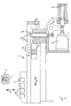
- the embodiment shown in the two figures of the tool holder 1 according to the invention relates to a tool holder, as in a machine tool 10 for Production of screws can be used.
- tool holder 1 On the illustrated tool holder 1 there are several tools 2, in this case press stamp, fixed and immovable arranged.
- the Figure 1 to the right of the press rams 2 another conventional tool holder 1 'in which a single Press tool 2 'is arranged.
- An arrangement of two different tool holders are often used if more than one in the manufacture of a pressed part, in this If two work steps are to be carried out.
- This die 3 is usually a rotating die, so that several within this die Parts are in different stages of production.
- the Vorstauchers the preform of a screw in the die manufactured then the matrix becomes a Step further rotated to the next step by means of the pressing tool 2, which in the tool holder assembly 1 according to the invention, which to produce the final shape of the screw blank. After one The die can then be rotated further Screw blank are ejected from the die.
- a sensor system is used with the tool holder coupled, e.g. based on monitored press pressures perfect function of tools 2, i.e. the press stamp supervised. If there are any deviations, then by means of the tool holder 1 according to the invention damaged tool 2 from its working position pulled out and at the same time a subsequent one Tool moved into the working position. With the new The tool can then be restarted.
- the tool holder 1 in slidably mounted on a rail.
- This rail is in the Images not shown.
- the drive of the tool holder mounted in the rail A rack can be reached on the side of tool holder 1 5 arranged in the teeth, the teeth of a gear or a tooth roller 6 engage.
- the gear 6 is here by actuating the pneumatic Cylinder 7 rotated via a lever 8.
- the pneumatic cylinder 7 By controlling the pneumatic cylinder 7, the rod 17 of the pneumatic Tightened cylinder until the stop 18 on the housing of the pneumatic cylinder 7 comes to rest.
- the stop 18 the maximum path that the rod 17 execute can, definitely.
- this tool holder bores 12 in an upper region into which a positioning and locking pin 11 is inserted to position the tool holder to back up.
- the number of Positioning and locking holes determined. Each A tool is therefore assigned to a hole.
- the spring force can be applied to the pin by a lever 16 11 are deflected so that the spring and Direction of movement of the pin arranged perpendicular to each other could be.
- the tool holder 1 In order to reduce the weight of the moving parts, is, as already mentioned, the tool holder 1 from the rest Drive parts that move the tool holder 1 effect, decoupled. That is, the cylinder 7 and that Gear 6 are arranged in a stationary manner on the machine tool 10. Only the tool holder 1 leads with the on this arranged pressing tools 2, the working movement A to Pressing a part 4 which is in the die 3 is located.
- toothed roller 6 is provided with a sufficient width, so can during the entire stroke of the tool holder 1 the toothing of the rack 5 in the pressing movement Slide the toothing of the toothed roller 6 along.
- the tool holder 1 instead of the linear movement described B also perform a circular motion.
- the Tool holder rotated around an axis. On one certain radius around this axis of rotation, a Large number of equally spaced tools fixed and immovable be arranged one after the other in the event of wear the working position can be rotated.
- the rotation of the tool holder about its axis can be done here also carried out in different ways become.
- the described possibility of free-wheel storage the axis of the driving element can also be one rotating tool holder can be provided.
Landscapes
- Engineering & Computer Science (AREA)
- Mechanical Engineering (AREA)
- Mounting, Exchange, And Manufacturing Of Dies (AREA)
- Jigs For Machine Tools (AREA)
- Automatic Assembly (AREA)
- Punching Or Piercing (AREA)
- Gripping On Spindles (AREA)
Abstract
Description
- Figur 1
- Eine auf die wesentlichen Merkmale beschränkte Frontansicht des erfindungsgemäßen Werkzeughalters
- Figur 2
- Eine Seitenansicht des erfindungsgemäßen Werkzeughalters
Claims (17)
- Werkzeughalter (1) für eine Werkzeugmaschine (10), insbesondere für eine Presse, welcher mehrere Werkzeuge (2), insbesondere Pressen-Stempel, aufnimmt, wobei der Werkzeughalter (1) im Arbeitsvorgang (A) auf einen Teilehalter (3) (Matrize) zubewegt wird, in dem sich wenigstens ein zu bearbeitendes Teil (4) befindet, dadurch gekennzeichnet, daß jedes im Werkzeughalter (1) fest und unbeweglich angeordnete Werkzeug (2) durch eine Bewegung (B) des Werkzeughalters (1) in eine Arbeitsposition bewegbar ist.
- Werkzeughalter nach einem der vorherigen Ansprüche, dadurch gekennzeichnet, daß der Werkzeughalter (1) in einer Schiene verschieblich gelagert ist.
- Werkzeughalter nach einem der vorherigen Ansprüche, dadurch gekennzeichnet, daß am Werkzeughalter (1) eine Zahnstange (5) angeordnet ist, in deren Zähne die Zähne eines Zahnrades (6) eingreifen.
- Werkzeughalter nach einem der vorherigen Ansprüche, dadurch gekennzeichnet, daß das Zahnrad (6) durch Betätigung eines pneumatischen Zylinders (7) über einen Hebel (8) gedreht wird.
- Werkzeughalter nach einem der vorherigen Ansprüche, dadurch gekennzeichnet, daß die Drehachse (9) des Zahnrades (6) freilaufgelagert ist.
- Werkzeughalter nach einem der vorherigen Ansprüche, dadurch gekennzeichnet, daß durch Betätigung des Zylinders (7) der Werkzeughalter (1) um eine Werkzeugposition weiterbewegbar ist.
- Werkzeughalter nach einem der vorherigen Ansprüche, dadurch gekennzeichnet, daß die Abstände (D) zwischen den im Werkzeughalter (1) angeordneten Werkzeugen (2) gleich sind.
- Werkzeughalter nach einem der vorherigen Ansprüche, dadurch gekennzeichnet, daß Zylinder (7) und Zahnrad (6) an der Werkzeugmaschine (10) ortsfest angeordnet sind und der Werkzeughalter (1) mit Zahnstange (5) die Arbeitsbewegung (A) ausführt.
- Werkzeughalter nach einem der vorherigen Ansprüche, dadurch gekennzeichnet, daß die Verzahnung der Zahnstange (5) in der Verzahnung des Zahnrades (6) gleitet.
- Werkzeughalter nach einem der vorherigen Ansprüche, dadurch gekennzeichnet, daß der Werkzeughalter (1) nach einer Bewegung (B) und Erreichen der Arbeitsposition eines Werkzeugs (2) feinpositionier- und arretierbar ist.
- Werkzeughalter nach Anspruch 10, dadurch gekennzeichnet, daß zur Feinpositionierung und Arretierung ein Stift (11) in eine dem benutzten Werkzeug (2) zugeordnete Positionierungs- und Arretierungsbohrung (12) einführbar ist.
- Werkzeughalter nach einem der vorherigen Ansprüche, dadurch gekennzeichnet, daß Stift (11) und Bohrung (12) zueinander passende Konusformen (13) aufweisen.
- Werkzeughalter nach einem der vorherigen Ansprüche, dadurch gekennzeichnet, daß die Abstände (D')zwischen den Bohrungen (12) den Abständen (D) zwischen den Werkzeugen (2) entsprechen.
- Werkzeughalter nach einem der vorherigen Ansprüche, dadurch gekennzeichnet, daß der Stift (11) durch Federbelastung (14) in den Konus (13) der Bohrung (12) eingepreßt ist.
- Werkzeughalter nach einem der vorherigen Ansprüche, dadurch gekennzeichnet, daß der Stift (11) durch Betätigung eines pneumatischen Zylinders (15) gegen die Federbelastung (14), insbesondere über einen Hebel (16) aus der Bohrung (12) herausgezogen wird.
- Werkzeughalter nach einem der vorherigen Ansprüche, dadurch gekennzeichnet, daß der Werkzeughalter um eine Achse drehbar gelagert ist.
- Werkzeughalter nach einem der vorherigen Ansprüche, dadurch gekennzeichnet, daß der Werkzeughalter zur Positionierung eines neuen Werkzeuges in die Arbeitsposition um einen konstanten Winkelbetrag drehbar ist.
Applications Claiming Priority (2)
| Application Number | Priority Date | Filing Date | Title |
|---|---|---|---|
| DE19854150A DE19854150A1 (de) | 1998-11-24 | 1998-11-24 | Werkzeughalter |
| DE19854150 | 1998-11-24 |
Publications (4)
| Publication Number | Publication Date |
|---|---|
| EP1004394A2 true EP1004394A2 (de) | 2000-05-31 |
| EP1004394A3 EP1004394A3 (de) | 2002-03-20 |
| EP1004394B1 EP1004394B1 (de) | 2008-12-03 |
| EP1004394B9 EP1004394B9 (de) | 2009-04-22 |
Family
ID=7888827
Family Applications (1)
| Application Number | Title | Priority Date | Filing Date |
|---|---|---|---|
| EP99119230A Expired - Lifetime EP1004394B9 (de) | 1998-11-24 | 1999-09-28 | Werkzeughalter für eine Werkzeugmaschine |
Country Status (5)
| Country | Link |
|---|---|
| US (1) | US6298708B1 (de) |
| EP (1) | EP1004394B9 (de) |
| JP (1) | JP4764965B2 (de) |
| AT (1) | ATE416063T1 (de) |
| DE (2) | DE19854150A1 (de) |
Families Citing this family (3)
| Publication number | Priority date | Publication date | Assignee | Title |
|---|---|---|---|---|
| CN116423136B (zh) * | 2023-06-13 | 2023-08-29 | 成都市鸿侠科技有限责任公司 | 一种前段四内蒙皮切割焊接工装 |
| CN116900778A (zh) * | 2023-06-30 | 2023-10-20 | 东风设备制造有限公司 | 一种加工中心方形刀库 |
| CN116587044B (zh) * | 2023-07-18 | 2023-10-20 | 宁波佳尔灵气动机械有限公司 | 一种气动多位置限位机构 |
Family Cites Families (15)
| Publication number | Priority date | Publication date | Assignee | Title |
|---|---|---|---|---|
| US1036047A (en) * | 1911-02-13 | 1912-08-20 | Waterbury Farrel Foundry Co | Mechanical movement. |
| US1297429A (en) * | 1918-05-28 | 1919-03-18 | Waterbury Farrel Foundry Co | Heading-machine. |
| US1905084A (en) * | 1930-11-28 | 1933-04-25 | United Screw And Bolt Corp | Manufacture of bolts |
| US1955061A (en) * | 1933-03-17 | 1934-04-17 | Nat Machinery Co | Double stroke cold header |
| US2104297A (en) * | 1936-11-04 | 1938-01-04 | Nat Machinery Co | Double stroke cold header |
| US2124022A (en) * | 1937-05-10 | 1938-07-19 | Arthur J Alberts | Heading method |
| US2204043A (en) * | 1939-01-24 | 1940-06-11 | Greenwood & Batley Ltd | Cold forging machine |
| US3359580A (en) * | 1965-07-19 | 1967-12-26 | Csavaraugyar | Method for producing shaped-head screws and tool for carrying out the method |
| DE2423574C3 (de) * | 1974-05-15 | 1978-05-03 | Dr. Eugen Duerrwaechter Doduco, 7530 Pforzheim | Doppeldruckpresse zum Herstellen von Kleinteilen aus Metall |
| DE2436862C2 (de) * | 1974-07-31 | 1986-11-13 | Thyssen Industrie Ag, 4300 Essen | Werkzeugwechselvorrichtung für Schmiedepressen |
| IT1134823B (it) * | 1980-12-19 | 1986-08-20 | Eufemia Garlaschi | Pressa a due matrici e quattro punzoni per la produzione di viti,bulloni,rivetti e simili organi sagomati |
| JPS6099035A (ja) * | 1983-11-04 | 1985-06-01 | 東レ株式会社 | スラブ糸の製造方法 |
| GB2161733A (en) * | 1984-07-09 | 1986-01-22 | Seagar Control Systems Limited | Punch press |
| DE3818001C3 (de) * | 1988-05-27 | 1998-02-12 | Trumpf Gmbh & Co | Stanzmaschine mit ein- und auswechselbarem Stanzwerkzeug und mit einem Werkstückvorschub |
| DE3900668C2 (de) * | 1989-01-09 | 2001-01-11 | Mannesmann Ag | Presse zum seitlichen Stauchen von Werkstücken, insbesondere Brammenstauchpresse |
-
1998
- 1998-11-24 DE DE19854150A patent/DE19854150A1/de not_active Withdrawn
-
1999
- 1999-09-28 AT AT99119230T patent/ATE416063T1/de not_active IP Right Cessation
- 1999-09-28 DE DE59914919T patent/DE59914919D1/de not_active Expired - Lifetime
- 1999-09-28 EP EP99119230A patent/EP1004394B9/de not_active Expired - Lifetime
- 1999-11-23 US US09/447,695 patent/US6298708B1/en not_active Expired - Fee Related
- 1999-11-24 JP JP33259599A patent/JP4764965B2/ja not_active Expired - Fee Related
Also Published As
| Publication number | Publication date |
|---|---|
| JP4764965B2 (ja) | 2011-09-07 |
| DE19854150A1 (de) | 2000-05-25 |
| EP1004394A3 (de) | 2002-03-20 |
| EP1004394B1 (de) | 2008-12-03 |
| DE59914919D1 (de) | 2009-01-15 |
| ATE416063T1 (de) | 2008-12-15 |
| EP1004394B9 (de) | 2009-04-22 |
| JP2000158272A (ja) | 2000-06-13 |
| US6298708B1 (en) | 2001-10-09 |
Similar Documents
| Publication | Publication Date | Title |
|---|---|---|
| DE69202034T2 (de) | Ohne-Griff-Typ Werkzeughalter. | |
| EP0369211A2 (de) | Spannvorrichtung zur Verbindung von Werkzeugkopf und Werkzeughalter an Werkzeugmaschinen | |
| EP0121826A2 (de) | Stanz- und Biegewerkzeug-Aggregat | |
| DE10024340C2 (de) | Stempel für Rundlaufpresse | |
| EP0212198B1 (de) | Kraftbetätigtes Spannfutter | |
| EP3849863B1 (de) | Bremszylinder mit einer verriegelungsvorrichtung zur mechanischen bremskraftverriegelung | |
| DE2211213B2 (de) | Vorrichtung an einer Presse zum schrittweisen Transport von Werkstücken in einem Stufenwerkzeug | |
| DE2748235C3 (de) | Gesenkschmiedepresse | |
| DE1577246C3 (de) | Sicherungseinrichtung für Arbeitsmaschinen | |
| EP1004394B1 (de) | Werkzeughalter für eine Werkzeugmaschine | |
| EP0314975B1 (de) | Presse mit Verriegelungseinrichtungen für den Stössel | |
| EP1348500B1 (de) | Vorrichtung zum intermittierenden Zuführen eines bandförmigen Rohlings | |
| DE3025844A1 (de) | Zufuhr- und abhubsteuerung fuer werkzeugschlitten | |
| EP2886224B1 (de) | Gewinderollkopf | |
| DE2911576A1 (de) | Schnellaufende maschine zum kaltschmieden von schrauben, nieten u.ae. hartwaren | |
| EP0534214B1 (de) | Verfahren und Vorrichtung zur Korrektur trapezartiger Passerabweichungen | |
| EP0666345B1 (de) | Vorrichtung zum Anbringen eines Antriebselementes auf einer Kettbaumwelle bei einer Webmaschine | |
| EP1345715B1 (de) | Schmiedepresse mit stellvorrichtung auf matrizenseite | |
| EP1380366A1 (de) | Vorschubvorrichtung zum intermittierenden Zuführen eines bandförmigen Rohlings zu einer Presse und Verfahren zum Betrieb derselben | |
| DE19837756C1 (de) | Einrichtung, um eine Drehbewegung von der Kurbelwelle in einen kurbelwellengetriebenen Schlitten einzuleiten | |
| DE2719065A1 (de) | Schraubturm zum einschrauben und ausschrauben grosser schraubenbolzen | |
| DE10247566B4 (de) | Radialrollkopf | |
| AT524952B1 (de) | Kettenfräsvorrichtung zum Ausfräsen einer taschenförmigen Ausnehmung in einer Möbelplatte zur Aufnahme eines Möbelbeschlags | |
| DE3808769C2 (de) | ||
| EP1046439A2 (de) | Rolle für einen Radialgewinderollkopf |
Legal Events
| Date | Code | Title | Description |
|---|---|---|---|
| PUAI | Public reference made under article 153(3) epc to a published international application that has entered the european phase |
Free format text: ORIGINAL CODE: 0009012 |
|
| AK | Designated contracting states |
Kind code of ref document: A2 Designated state(s): AT BE CH CY DE DK ES FI FR GB GR IE IT LI LU MC NL PT SE |
|
| AX | Request for extension of the european patent |
Free format text: LT;LV;RO;SI |
|
| PUAL | Search report despatched |
Free format text: ORIGINAL CODE: 0009013 |
|
| AK | Designated contracting states |
Kind code of ref document: A3 Designated state(s): AT BE CH CY DE DK ES FI FR GB GR IE IT LI LU MC NL PT SE |
|
| AX | Request for extension of the european patent |
Free format text: LT;LV;RO;SI |
|
| RIC1 | Information provided on ipc code assigned before grant |
Free format text: 7B 23Q 3/18 A, 7B 23Q 16/04 B, 7B 23Q 39/02 B, 7B 30B 15/06 B, 7B 23Q 3/155 B, 7B 21J 13/08 B |
|
| 17P | Request for examination filed |
Effective date: 20020810 |
|
| AKX | Designation fees paid |
Free format text: AT BE CH CY DE DK ES FI FR GB GR IE IT LI LU MC NL PT SE |
|
| 17Q | First examination report despatched |
Effective date: 20070814 |
|
| GRAP | Despatch of communication of intention to grant a patent |
Free format text: ORIGINAL CODE: EPIDOSNIGR1 |
|
| GRAS | Grant fee paid |
Free format text: ORIGINAL CODE: EPIDOSNIGR3 |
|
| GRAS | Grant fee paid |
Free format text: ORIGINAL CODE: EPIDOSNIGR3 |
|
| GRAA | (expected) grant |
Free format text: ORIGINAL CODE: 0009210 |
|
| AK | Designated contracting states |
Kind code of ref document: B1 Designated state(s): AT BE CH CY DE DK ES FI FR GB GR IE IT LI LU MC NL PT SE |
|
| REG | Reference to a national code |
Ref country code: GB Ref legal event code: FG4D Free format text: NOT ENGLISH |
|
| REG | Reference to a national code |
Ref country code: CH Ref legal event code: EP |
|
| REG | Reference to a national code |
Ref country code: IE Ref legal event code: FG4D Free format text: LANGUAGE OF EP DOCUMENT: GERMAN |
|
| REF | Corresponds to: |
Ref document number: 59914919 Country of ref document: DE Date of ref document: 20090115 Kind code of ref document: P |
|
| PG25 | Lapsed in a contracting state [announced via postgrant information from national office to epo] |
Ref country code: ES Free format text: LAPSE BECAUSE OF FAILURE TO SUBMIT A TRANSLATION OF THE DESCRIPTION OR TO PAY THE FEE WITHIN THE PRESCRIBED TIME-LIMIT Effective date: 20090314 |
|
| NLV1 | Nl: lapsed or annulled due to failure to fulfill the requirements of art. 29p and 29m of the patents act | ||
| PG25 | Lapsed in a contracting state [announced via postgrant information from national office to epo] |
Ref country code: NL Free format text: LAPSE BECAUSE OF FAILURE TO SUBMIT A TRANSLATION OF THE DESCRIPTION OR TO PAY THE FEE WITHIN THE PRESCRIBED TIME-LIMIT Effective date: 20081203 Ref country code: FI Free format text: LAPSE BECAUSE OF FAILURE TO SUBMIT A TRANSLATION OF THE DESCRIPTION OR TO PAY THE FEE WITHIN THE PRESCRIBED TIME-LIMIT Effective date: 20081203 |
|
| REG | Reference to a national code |
Ref country code: IE Ref legal event code: FD4D |
|
| PG25 | Lapsed in a contracting state [announced via postgrant information from national office to epo] |
Ref country code: IE Free format text: LAPSE BECAUSE OF FAILURE TO SUBMIT A TRANSLATION OF THE DESCRIPTION OR TO PAY THE FEE WITHIN THE PRESCRIBED TIME-LIMIT Effective date: 20081203 |
|
| PG25 | Lapsed in a contracting state [announced via postgrant information from national office to epo] |
Ref country code: SE Free format text: LAPSE BECAUSE OF FAILURE TO SUBMIT A TRANSLATION OF THE DESCRIPTION OR TO PAY THE FEE WITHIN THE PRESCRIBED TIME-LIMIT Effective date: 20090303 Ref country code: PT Free format text: LAPSE BECAUSE OF FAILURE TO SUBMIT A TRANSLATION OF THE DESCRIPTION OR TO PAY THE FEE WITHIN THE PRESCRIBED TIME-LIMIT Effective date: 20090504 |
|
| PLBE | No opposition filed within time limit |
Free format text: ORIGINAL CODE: 0009261 |
|
| STAA | Information on the status of an ep patent application or granted ep patent |
Free format text: STATUS: NO OPPOSITION FILED WITHIN TIME LIMIT |
|
| PG25 | Lapsed in a contracting state [announced via postgrant information from national office to epo] |
Ref country code: DK Free format text: LAPSE BECAUSE OF FAILURE TO SUBMIT A TRANSLATION OF THE DESCRIPTION OR TO PAY THE FEE WITHIN THE PRESCRIBED TIME-LIMIT Effective date: 20081203 |
|
| 26N | No opposition filed |
Effective date: 20090904 |
|
| PGFP | Annual fee paid to national office [announced via postgrant information from national office to epo] |
Ref country code: DE Payment date: 20090923 Year of fee payment: 11 |
|
| BERE | Be: lapsed |
Owner name: GEBR. HILGELAND G.M.B.H. & CO. Effective date: 20090930 |
|
| PG25 | Lapsed in a contracting state [announced via postgrant information from national office to epo] |
Ref country code: MC Free format text: LAPSE BECAUSE OF NON-PAYMENT OF DUE FEES Effective date: 20090930 |
|
| REG | Reference to a national code |
Ref country code: CH Ref legal event code: PL |
|
| GBPC | Gb: european patent ceased through non-payment of renewal fee |
Effective date: 20090928 |
|
| REG | Reference to a national code |
Ref country code: FR Ref legal event code: ST Effective date: 20100531 |
|
| PG25 | Lapsed in a contracting state [announced via postgrant information from national office to epo] |
Ref country code: FR Free format text: LAPSE BECAUSE OF NON-PAYMENT OF DUE FEES Effective date: 20090930 |
|
| PG25 | Lapsed in a contracting state [announced via postgrant information from national office to epo] |
Ref country code: BE Free format text: LAPSE BECAUSE OF NON-PAYMENT OF DUE FEES Effective date: 20090930 |
|
| PG25 | Lapsed in a contracting state [announced via postgrant information from national office to epo] |
Ref country code: LI Free format text: LAPSE BECAUSE OF NON-PAYMENT OF DUE FEES Effective date: 20090930 Ref country code: GR Free format text: LAPSE BECAUSE OF FAILURE TO SUBMIT A TRANSLATION OF THE DESCRIPTION OR TO PAY THE FEE WITHIN THE PRESCRIBED TIME-LIMIT Effective date: 20090304 Ref country code: CH Free format text: LAPSE BECAUSE OF NON-PAYMENT OF DUE FEES Effective date: 20090930 |
|
| PG25 | Lapsed in a contracting state [announced via postgrant information from national office to epo] |
Ref country code: GB Free format text: LAPSE BECAUSE OF NON-PAYMENT OF DUE FEES Effective date: 20090928 Ref country code: AT Free format text: LAPSE BECAUSE OF NON-PAYMENT OF DUE FEES Effective date: 20090928 |
|
| PG25 | Lapsed in a contracting state [announced via postgrant information from national office to epo] |
Ref country code: IT Free format text: LAPSE BECAUSE OF FAILURE TO SUBMIT A TRANSLATION OF THE DESCRIPTION OR TO PAY THE FEE WITHIN THE PRESCRIBED TIME-LIMIT Effective date: 20081203 |
|
| PG25 | Lapsed in a contracting state [announced via postgrant information from national office to epo] |
Ref country code: LU Free format text: LAPSE BECAUSE OF NON-PAYMENT OF DUE FEES Effective date: 20090928 |
|
| REG | Reference to a national code |
Ref country code: DE Ref legal event code: R119 Ref document number: 59914919 Country of ref document: DE Effective date: 20110401 |
|
| PG25 | Lapsed in a contracting state [announced via postgrant information from national office to epo] |
Ref country code: DE Free format text: LAPSE BECAUSE OF NON-PAYMENT OF DUE FEES Effective date: 20110401 |
|
| PG25 | Lapsed in a contracting state [announced via postgrant information from national office to epo] |
Ref country code: CY Free format text: LAPSE BECAUSE OF FAILURE TO SUBMIT A TRANSLATION OF THE DESCRIPTION OR TO PAY THE FEE WITHIN THE PRESCRIBED TIME-LIMIT Effective date: 20081203 |