EP1004442A2 - Auf dem angewandten Druckmodus basierende Variation der Steuerleistung, welche einer Tintenstrahlkassette zugeführt wird - Google Patents
Auf dem angewandten Druckmodus basierende Variation der Steuerleistung, welche einer Tintenstrahlkassette zugeführt wird Download PDFInfo
- Publication number
- EP1004442A2 EP1004442A2 EP99308598A EP99308598A EP1004442A2 EP 1004442 A2 EP1004442 A2 EP 1004442A2 EP 99308598 A EP99308598 A EP 99308598A EP 99308598 A EP99308598 A EP 99308598A EP 1004442 A2 EP1004442 A2 EP 1004442A2
- Authority
- EP
- European Patent Office
- Prior art keywords
- primitive
- printer
- print cartridge
- firing
- resistors
- Prior art date
- Legal status (The legal status is an assumption and is not a legal conclusion. Google has not performed a legal analysis and makes no representation as to the accuracy of the status listed.)
- Granted
Links
- 238000010304 firing Methods 0.000 claims abstract description 69
- 230000003071 parasitic effect Effects 0.000 claims abstract description 25
- 238000000034 method Methods 0.000 claims abstract description 23
- 230000000694 effects Effects 0.000 claims description 5
- 238000007639 printing Methods 0.000 description 29
- 239000000758 substrate Substances 0.000 description 13
- 238000004519 manufacturing process Methods 0.000 description 6
- 238000010586 diagram Methods 0.000 description 5
- 238000007641 inkjet printing Methods 0.000 description 4
- 239000007788 liquid Substances 0.000 description 3
- 230000000994 depressogenic effect Effects 0.000 description 2
- 238000007726 management method Methods 0.000 description 2
- 230000008569 process Effects 0.000 description 2
- 230000001105 regulatory effect Effects 0.000 description 2
- 230000004044 response Effects 0.000 description 2
- 240000000254 Agrostemma githago Species 0.000 description 1
- 235000009899 Agrostemma githago Nutrition 0.000 description 1
- 108091081062 Repeated sequence (DNA) Proteins 0.000 description 1
- XUIMIQQOPSSXEZ-UHFFFAOYSA-N Silicon Chemical compound [Si] XUIMIQQOPSSXEZ-UHFFFAOYSA-N 0.000 description 1
- 230000004888 barrier function Effects 0.000 description 1
- 230000002457 bidirectional effect Effects 0.000 description 1
- 230000015572 biosynthetic process Effects 0.000 description 1
- 230000000903 blocking effect Effects 0.000 description 1
- 239000003086 colorant Substances 0.000 description 1
- 230000001010 compromised effect Effects 0.000 description 1
- 239000004020 conductor Substances 0.000 description 1
- 230000001276 controlling effect Effects 0.000 description 1
- 238000012937 correction Methods 0.000 description 1
- 230000003247 decreasing effect Effects 0.000 description 1
- 230000007547 defect Effects 0.000 description 1
- 238000005516 engineering process Methods 0.000 description 1
- 238000002474 experimental method Methods 0.000 description 1
- 239000010408 film Substances 0.000 description 1
- 229920005570 flexible polymer Polymers 0.000 description 1
- 230000006870 function Effects 0.000 description 1
- 238000010438 heat treatment Methods 0.000 description 1
- 238000000608 laser ablation Methods 0.000 description 1
- 239000011159 matrix material Substances 0.000 description 1
- 230000007246 mechanism Effects 0.000 description 1
- 239000000049 pigment Substances 0.000 description 1
- 238000007665 sagging Methods 0.000 description 1
- 238000012163 sequencing technique Methods 0.000 description 1
- 229910052710 silicon Inorganic materials 0.000 description 1
- 239000010703 silicon Substances 0.000 description 1
- 239000002904 solvent Substances 0.000 description 1
- 239000010409 thin film Substances 0.000 description 1
- 238000009834 vaporization Methods 0.000 description 1
- 230000008016 vaporization Effects 0.000 description 1
Images

Classifications
-
- B—PERFORMING OPERATIONS; TRANSPORTING
- B41—PRINTING; LINING MACHINES; TYPEWRITERS; STAMPS
- B41J—TYPEWRITERS; SELECTIVE PRINTING MECHANISMS, i.e. MECHANISMS PRINTING OTHERWISE THAN FROM A FORME; CORRECTION OF TYPOGRAPHICAL ERRORS
- B41J2/00—Typewriters or selective printing mechanisms characterised by the printing or marking process for which they are designed
- B41J2/485—Typewriters or selective printing mechanisms characterised by the printing or marking process for which they are designed characterised by the process of building-up characters or image elements applicable to two or more kinds of printing or marking processes
- B41J2/505—Typewriters or selective printing mechanisms characterised by the printing or marking process for which they are designed characterised by the process of building-up characters or image elements applicable to two or more kinds of printing or marking processes from an assembly of identical printing elements
- B41J2/5056—Typewriters or selective printing mechanisms characterised by the printing or marking process for which they are designed characterised by the process of building-up characters or image elements applicable to two or more kinds of printing or marking processes from an assembly of identical printing elements using dot arrays providing selective dot disposition modes, e.g. different dot densities for high speed and high-quality printing, array line selections for multi-pass printing, or dot shifts for character inclination
-
- B—PERFORMING OPERATIONS; TRANSPORTING
- B41—PRINTING; LINING MACHINES; TYPEWRITERS; STAMPS
- B41J—TYPEWRITERS; SELECTIVE PRINTING MECHANISMS, i.e. MECHANISMS PRINTING OTHERWISE THAN FROM A FORME; CORRECTION OF TYPOGRAPHICAL ERRORS
- B41J2/00—Typewriters or selective printing mechanisms characterised by the printing or marking process for which they are designed
- B41J2/005—Typewriters or selective printing mechanisms characterised by the printing or marking process for which they are designed characterised by bringing liquid or particles selectively into contact with a printing material
- B41J2/01—Ink jet
- B41J2/015—Ink jet characterised by the jet generation process
- B41J2/04—Ink jet characterised by the jet generation process generating single droplets or particles on demand
- B41J2/045—Ink jet characterised by the jet generation process generating single droplets or particles on demand by pressure, e.g. electromechanical transducers
- B41J2/04501—Control methods or devices therefor, e.g. driver circuits, control circuits
- B41J2/04513—Control methods or devices therefor, e.g. driver circuits, control circuits for increasing lifetime
-
- B—PERFORMING OPERATIONS; TRANSPORTING
- B41—PRINTING; LINING MACHINES; TYPEWRITERS; STAMPS
- B41J—TYPEWRITERS; SELECTIVE PRINTING MECHANISMS, i.e. MECHANISMS PRINTING OTHERWISE THAN FROM A FORME; CORRECTION OF TYPOGRAPHICAL ERRORS
- B41J2/00—Typewriters or selective printing mechanisms characterised by the printing or marking process for which they are designed
- B41J2/005—Typewriters or selective printing mechanisms characterised by the printing or marking process for which they are designed characterised by bringing liquid or particles selectively into contact with a printing material
- B41J2/01—Ink jet
- B41J2/015—Ink jet characterised by the jet generation process
- B41J2/04—Ink jet characterised by the jet generation process generating single droplets or particles on demand
- B41J2/045—Ink jet characterised by the jet generation process generating single droplets or particles on demand by pressure, e.g. electromechanical transducers
- B41J2/04501—Control methods or devices therefor, e.g. driver circuits, control circuits
- B41J2/04541—Specific driving circuit
-
- B—PERFORMING OPERATIONS; TRANSPORTING
- B41—PRINTING; LINING MACHINES; TYPEWRITERS; STAMPS
- B41J—TYPEWRITERS; SELECTIVE PRINTING MECHANISMS, i.e. MECHANISMS PRINTING OTHERWISE THAN FROM A FORME; CORRECTION OF TYPOGRAPHICAL ERRORS
- B41J2/00—Typewriters or selective printing mechanisms characterised by the printing or marking process for which they are designed
- B41J2/005—Typewriters or selective printing mechanisms characterised by the printing or marking process for which they are designed characterised by bringing liquid or particles selectively into contact with a printing material
- B41J2/01—Ink jet
- B41J2/015—Ink jet characterised by the jet generation process
- B41J2/04—Ink jet characterised by the jet generation process generating single droplets or particles on demand
- B41J2/045—Ink jet characterised by the jet generation process generating single droplets or particles on demand by pressure, e.g. electromechanical transducers
- B41J2/04501—Control methods or devices therefor, e.g. driver circuits, control circuits
- B41J2/04543—Block driving
-
- B—PERFORMING OPERATIONS; TRANSPORTING
- B41—PRINTING; LINING MACHINES; TYPEWRITERS; STAMPS
- B41J—TYPEWRITERS; SELECTIVE PRINTING MECHANISMS, i.e. MECHANISMS PRINTING OTHERWISE THAN FROM A FORME; CORRECTION OF TYPOGRAPHICAL ERRORS
- B41J2/00—Typewriters or selective printing mechanisms characterised by the printing or marking process for which they are designed
- B41J2/005—Typewriters or selective printing mechanisms characterised by the printing or marking process for which they are designed characterised by bringing liquid or particles selectively into contact with a printing material
- B41J2/01—Ink jet
- B41J2/015—Ink jet characterised by the jet generation process
- B41J2/04—Ink jet characterised by the jet generation process generating single droplets or particles on demand
- B41J2/045—Ink jet characterised by the jet generation process generating single droplets or particles on demand by pressure, e.g. electromechanical transducers
- B41J2/04501—Control methods or devices therefor, e.g. driver circuits, control circuits
- B41J2/04568—Control according to number of actuators used simultaneously
-
- B—PERFORMING OPERATIONS; TRANSPORTING
- B41—PRINTING; LINING MACHINES; TYPEWRITERS; STAMPS
- B41J—TYPEWRITERS; SELECTIVE PRINTING MECHANISMS, i.e. MECHANISMS PRINTING OTHERWISE THAN FROM A FORME; CORRECTION OF TYPOGRAPHICAL ERRORS
- B41J2/00—Typewriters or selective printing mechanisms characterised by the printing or marking process for which they are designed
- B41J2/005—Typewriters or selective printing mechanisms characterised by the printing or marking process for which they are designed characterised by bringing liquid or particles selectively into contact with a printing material
- B41J2/01—Ink jet
- B41J2/015—Ink jet characterised by the jet generation process
- B41J2/04—Ink jet characterised by the jet generation process generating single droplets or particles on demand
- B41J2/045—Ink jet characterised by the jet generation process generating single droplets or particles on demand by pressure, e.g. electromechanical transducers
- B41J2/04501—Control methods or devices therefor, e.g. driver circuits, control circuits
- B41J2/0458—Control methods or devices therefor, e.g. driver circuits, control circuits controlling heads based on heating elements forming bubbles
-
- B—PERFORMING OPERATIONS; TRANSPORTING
- B41—PRINTING; LINING MACHINES; TYPEWRITERS; STAMPS
- B41J—TYPEWRITERS; SELECTIVE PRINTING MECHANISMS, i.e. MECHANISMS PRINTING OTHERWISE THAN FROM A FORME; CORRECTION OF TYPOGRAPHICAL ERRORS
- B41J2202/00—Embodiments of or processes related to ink-jet or thermal heads
- B41J2202/01—Embodiments of or processes related to ink-jet heads
- B41J2202/17—Readable information on the head
Definitions
- This invention relates to thermal inkjet printers, and more particularly to the control of the printhead firing energy.
- Thermal inkjet hardcopy devices such as printers, graphics plotters, facsimile machines and copiers have gained wide acceptance. These hardcopy devices are described by W.J. Lloyd and H.T. Taub in "Ink Jet Devices," Chapter 13 of Output Hardcopy Devices (Ed. R.C. Durbeck and S. Sherr, San Diego: Academic Press, 1988). The basics of this technology are further disclosed in various articles in several editions of the Hewlett-Packard Journal [Vol. 36, No. 5 (May 1985), Vol. 39, No. 4 (August 1988), Vol. 39, No. 5 (October 1988), Vol. 43, No. 4 (August 1992), Vol. 43, No. 6 (December 1992) and Vol. 45, No.1 (February 1994)], incorporated herein by reference. Inkjet hardcopy devices produce high quality print, are compact and portable, and print quickly and quietly because only ink strikes the paper.
- An inkjet printer forms a printed image by printing a pattern of individual dots at particular locations of an array defined for the printing medium.
- the locations are conveniently visualized as being small dots in a rectilinear array.
- the locations are sometimes "dot locations", “dot positions”, or pixels".
- the printing operation can be viewed as the filling of a pattern of dot locations with dots of ink.
- Inkjet hardcopy devices print dots by ejecting very small drops of ink onto the print medium and typically include a movable carriage that supports one or more printheads each having ink ejecting nozzles. The carriage traverses over the surface of the print medium, and the nozzles are controlled to eject drops of ink at appropriate times pursuant to command of a microcomputer or other controller, wherein the timing of the application of the ink drops is intended to correspond to the pattern of pixels of the image being printed.
- the typical inkjet printhead i.e., the silicon substrate, structures built on the substrate, and connections to the substrate
- liquid ink i.e., dissolved colorants or pigments dispersed in a solvent
- It has an array of precisely formed orifices or nozzles attached to a printhead substrate that incorporates an array of ink ejection chambers which receive liquid ink from the ink reservoir.
- Each chamber is located opposite the nozzle so ink can collect between it and the nozzle and has a firing resistor located in the chamber.
- the ejection of ink droplets is typically under the control of a microprocessor, the signals of which are conveyed by electrical traces to the resistor elements.
- inkjet printhead In an inkjet printhead the ink is fed from an ink reservoir integral to the printhead or an "off-axis" ink reservoir which feeds ink to the printhead via tubes connecting the printhead and reservoir. Ink is then fed to the various vaporization chambers either through an elongated hole formed in the center of the bottom of the substrate, "center feed”, or around the outer edges of the substrate, “edge feed.”
- the ink cartridge containing the nozzles is moved repeatedly across the width of the medium to be printed upon. At each of a designated number of increments of this movement across the medium, each of the resistors is caused either to eject ink or to refrain from ejecting ink according to the program output of the controlling microprocessor.
- Each completed movement across the medium can print a swath approximately as wide as the number of nozzles arranged in a column of the ink cartridge multiplied times the distance between nozzle centers. After each such completed movement or swath the medium is moved forward the width of the swath, and the ink cartridge begins the next swath. By proper selection and timing of the signals, the desired print is obtained on the medium.
- the energy applied to a firing'resistor affects performance, durability and efficiency. It is well known that the firing energy must be above a certain firing threshold to cause a vapor bubble to nucleate. Above this firing threshold is a transitional range where increasing the firing energy increases the volume of ink expelled. Above this transitional range, there is a higher optimal range where drop volumes do not increase with increasing firing energy. In this optimal range above the optimal firing threshold drop volumes are stable even with moderate firing energy variations. Since, variations in drop volume cause disuniformities in printed output, it is in this optimal range that printing ideally takes place. As energy levels increase in this optimal range, uniformity is not compromised, but energy is wasted and the printhead is prematurely aged due to excessive heating and ink residue build-up.
- a one time calibration of each connection by either the printer or production circuitry external to the print cartridge also compensates for any parasitic resistance or impedance in the unique path leading to each resistor.
- Printheads may be characterized at production to set these operating parameters. The printer then uses these operating parameters.
- each firing resistor or each primitive does not have a dedicated connection
- a large number of resistors is powered by a single voltage line that receives power via an electrical contact pad between the printer electronics and the removable print cartridge. Consequently, as the data load being printed changes, the current draw through the line and the voltage as measured at the firing resistor may be undesirably varied. For instance, when many or all resistors are fired simultaneously, the print cartridge voltage may be depressed by parasitic effects, giving a lower firing voltage than when only one or a few resistors are fired.
- the present invention provides a method of operating an inkjet printer having one or more inkjet print cartridges installed in the printer, wherein the printer is capable of operating under varying operating conditions and in a plurality of different printmodes, including obtaining a value for the common parasitic resistances and a base operating voltage setting for the inkjet printer when a predetermined number of possible resistors on the print cartridge are firing during a given period of time, determining an actual number of resistors firing on the print cartridge during the given period of time, adjusting the base operating voltage setting to a selected voltage setting based on the results of said obtaining step and said determining step and operating the printer using the selected operating voltage setting for the print cartridge.
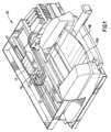
- Fig. 1 is a perspective view of one embodiment of an inkjet printer incorporating the present invention.
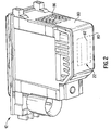
- Fig. 2 is a top perspective view of a single print cartridge.
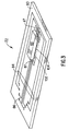
- Fig. 3 is a highly schematic perspective view of the back side of a very simplified printhead assembly.
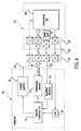
- Fig. 4 is a schematic block diagram of a thermal inkjet printing apparatus according to a preferred embodiment of the invention.
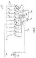
- Fig. 5 is a detailed schematic of a printhead circuit of the embodiment of Fig. 2.
- Fig. 6 is a schematic block diagram of a power supply, voltage regulator and a single print cartridge circuit.
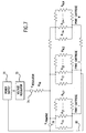
- Fig. 7 is a schematic block diagram showing a power supply, voltage regulator and multiple print cartridge circuits.
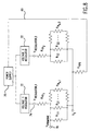
- Fig. 8 is a schematic block diagram showing a power supply, two voltage regulators and multiple print cartridge circuits.
- Fig. 1 is a perspective view of one embodiment of an inkjet printer 10 suitable for utilizing the present invention, with its cover removed.
- printer 10 includes a tray 11A for holding virgin paper.
- a sheet of paper from input tray 11A is fed into printer 10 using a sheet feeder, then brought around in a U direction to now travel in the opposite direction toward output tray 11B.
- the sheet is stopped in a print zone 13, and a scanning carriage 16, supporting one or more print cartridges 12, is then passed across a print zone on the sheet for printing a swath of ink thereon.
- the printing may occur while the carriage is passing in either directional. This is referred to as bi-directional printing.
- the sheet is then incrementally shifted an amount based on the printmode being used, using a conventional stepper motor and feed rollers to a next position within the print zone 13, and carriage 16 again passes across the sheet for printing a next swath of ink.
- the sheet is forwarded to a position above tray 13, held in that position to ensure the ink is dry and then released.
- the carriage 16 scanning mechanism may be conventional and generally includes a slide rod, along which carriage 16 slides, a flexible cable (not shown in Fig. 1) for transmitting electrical signals from the printer's controller to the carriage 16 and then to electrodes on the carriage 16 which engage electrical contacts 86 on print cartridges 12 when they are installed in the printer.
- a motor (not shown), connected to carriage 16 using a conventional drive belt and pulley arrangement, may be used for transporting carriage 16 across print zone 14.
- Fig. 2 illustrates a print cartridge 12 having a printhead assembly 22 attached which includes a flexible tape 80 containing nozzles 82 and electrical contact pads 86.
- the contact pads 86 align with and electrically contact electrodes (not shown) on carriage 16.
- the print cartridge also includes a memory device for storing calibration information determined on the manufacturing line or subsequently. Values typically include operating voltage, operating energy, turn-on energy, print cartridge resistances including common parasitic resistances and drop volumes. This information can the be read and stored by the printer when the print cartridge is installed in the printer.
- printhead assembly 22 is preferably a flexible polymer tape 80, containing nozzles 82 formed therein by laser ablation, attached to a substrate, or die, 88 having ink ejection elements, or resistors, 44 formed thereon.
- Conductive traces 84 are formed on the back of tape 80 and terminate in contact pads 86 for contacting electrical contacts on carriage 16. The other ends of conductors 84 are bonded to electrodes 87 of substrate 88.
- Ink ejection chambers 102 are formed in a barrier layer 104 between the substrate 88 and the tape 80.
- Fig. 4 shows a schematic block diagram of an inkjet printer 10 with a connected print cartridge 12.
- a controller 14 in the printer 10 receives print data from a computer or microprocessor (not shown) and processes the data to provide printer control information or image data to a printhead driver circuit 15.
- a controlled voltage power supply 17 provides a controlled voltage to a power bus 18.
- a memory reader circuit 19 in the printer 10 is connected to the controller 14 for transmitting information received from the print cartridge 12 via a memory line 20.
- the printhead driver circuit 15 is controlled by the controller 14 to send the image data to a printhead die 88 on the print cartridge 12, via a control bus 24.
- the cartridge 12 is removably replaceable and is electrically connected to the printer 10 by the control bus 24, power bus 18 and memory line 20.
- a connector interface 26 has a conductive pin for each line on the printer carriage side contacting a corresponding pad 86 on a flexible circuit tape 80 on the cartridge 12.
- a memory chip 31 on the cartridge stores printer control information programmed during manufacture of the cartridge and used by the printer during operation.
- the flex circuit 80 is connected to the printhead die 88 via bonds to electrodes 87.
- An analog-to-digital converter 34 in the printer is connected to the printhead to receive data from the printhead that indicates the printhead's temperature.
- Fig. 5 shows a firing control circuit 40 and an exemplary fraction of the many resistors 44 on the printhead 22.
- Printhead 22 includes substrate 88 having firing resistors 44 and nozzles 82 in tape 80.
- the firing control circuit 40 resides on the printhead 22 substrate 88 and has a single pad to pad voltage input (“V pp ”) 46 from the power bus 18 commonly connected to a set 42 of thin film firing resistors 44.
- Each firing resistor 44 is connected to a corresponding firing switch 48 connected to a ground line 50 and having a control input connected to the output 54 of a firing pulse modulator 52.
- the firing pulse modulator 52 receives print data on a bus 60 and outputs a firing signal on output lines 54 to each selected firing switch 48.
- the printer To fire a selected group of the resistor set 42, the printer sends an input voltage V pp on line 46, and transmits a full-duration firing pulse 58 on line 56.
- the firing pulse modulator 52 transmits the firing pulse 58 to the resistor firing switches 48, causing the selected switches to close and connecting the resistors to ground to allow current flow through the resistors 44 to generate firing energy.
- the printhead assembly 22 has a large number of nozzles 82 with a firing resistor 44 associated with each nozzle 82.
- the interconnections to the resistors 44 in an integrated drive printhead are multiplexed.
- the print driver circuitry comprises an array of primitive lines 46, primitive commons 50, and address select lines 54 to control ink ejections elements 44.
- the printhead 22 may be arranged into any number of multiple similar subsections, such as quadrants, with each subsection being powered separately and having a particular number of primitives containing a particular number of resistors.
- Specifying an address line 54 and a primitive line 46 uniquely identifies one particular ink ejection element 44.
- the number of resistors within a primitive is equal to the number of address lines. Any combination of address lines and primitive select lines could be used, however, it is useful to minimize the number of address lines in order to minimize the time required to cycle through the address lines.
- Each ink ejection element is controlled by its own drive transistor 48, which shares its control input address select with the number of ejection elements 44 in a primitive.
- Each ink ejection element is tied to other ink ejection elements 44 by a common node primitive select. Consequently, firing a particular ink ejection element requires applying a control voltage at its address select terminal and an electrical power source at its primitive select terminal.
- each primitive is selectively energized by powering the associated primitive select interconnection. To provide uniform energy per heater ink ejection element only one ink ejection element is energized at a time per primitive. However, any number of the primitive selects may be enabled concurrently. Each enabled primitive select thus delivers both power and one of the enable signals to the driver transistor.
- the other enable signal is an address signal provided by each address select line only one of which is active at a time.
- Each address select line is tied to all of the switching transistors 82 so that all such switching devices are conductive when the interconnection is enabled.
- a primitive select interconnection and an address select line for a ink ejection element are both active simultaneously, that particular heater ink ejection element is energized. Only one address select line is enabled at one time. This ensures that the primitive select and group return lines supply current to at most one ink ejection element at a time. Otherwise, the energy delivered to a heater ink ejection element would be a function of the number of ink ejection elements being energized at the same time.
- a set of resistors, or a primitive is powered by a single voltage line that receives power via an electrical interconnection between the print cartridge electrical pads 86 and corresponding pads on the printer carriage 16.
- Power to the carriage 16 from the regulated voltage 72 on the printer 10 is suppled by a flexible cable, or ribbon cable.
- the voltage line continues from the electrical contact pads 86 on a flexible electrical tape circuit 80 to a bonding connection to electrodes 87 on the printhead die 88.
- the printhead die 88 contains the firing resistors 44 and other control electronics, such as the drive transistors 48.
- the voltage line continues out from the printhead die 88 via a bonding connection to electrodes 87 on the printhead die 88 through the flexible electrical tape circuit 80 to print cartridge electrical pads.
- the voltage line continues to the carriage electrical interconnection between the print cartridge electrical pads 86 and to corresponding pads on the printer carriage 16.
- the voltage line continues from the carriage 16 to the voltage regulator 72 via the flexible cable, or ribbon cable.
- the impedance of the print cartridge electrical contacts 86, flex circuit 80 bonding connections to the substrate, flex circuit trace resistances, substrate trace, transistor, resistor resistances, and other connections and lines, can vary from print cartridge to print cartridge. Also, the impedance of the print cartridge can vary over time, even when the voltage provided by the printer to each of the print cartridge electrical contacts is well controlled. Moreover, as the data load being printed changes, the current draw through the line and the voltage as measured at the firing resistor may be undesirably varied. For instance, when many or all resistors are fired simultaneously, the print cartridge voltage may be depressed by parasitic effects, giving a lower firing voltage than when only one or a few resistors are fired.
- the voltage is regulated prior to the carriage to print cartridge interconnect, there is no consideration of the resistance past that point.
- heavy loading i.e. single pass and/or high density prints
- the parasitic voltage drop can be quite high. Since, the turn-on energy is set such that heavy loads can print, light loads (i.e. multiple pass and/or low density prints), which do not experience nearly as high a voltage loss through the lines, can be given significant amounts of over-energy.
- the power supply voltage is set to a level adequate to ensure adequate firing energy levels for full drop volume firing in "blackout conditions," i.e., when a predetermined number of resistors are fired simultaneously. Because firing energy is proportional to the product of the square of the voltage and the time duration, the power supply voltage must be high enough to provide adequate energy within the limited time afforded for printing each dot, before the next dot is to be printed at the desired printer scan rate. Part of the calibration process includes establishing a voltage to provide a firing energy threshold for all firing conditions, regardless of the number of resistors being fired simultaneously.
- printmode The specific dot pattern placed on the media in each pass and the way in which these different dot patterns add up to a final complete image, is known as a "printmode.”
- the concept of printmodes is a useful and well-known technique of laying down in each pass of the printhead only a fraction of the total ink required in each section of the image, so that any areas left white in each pass are filled in by one or more later passes. This tends to control bleed, blocking and cockle by reducing the amount of liquid that is on the page at any given time.
- Printmodes allow a trade-off between speed and image quality. For example, a printer's draft mode provides the user with readable text as quickly as possible. Presentation, also known as best mode, is slow but produces the highest image quality.
- Normal mode is a compromise between draft and presentation modes.
- Printmodes allow the user to choose between these trade-offs. It also allows the printer to control several factors during printing that influence image quality, including: 1) the amount of ink placed on the media per dot location, 2) the speed with which the ink is placed, and, 3) the number of passes required to complete the image. Providing different printmodes to allow placing ink drops in multiple swaths can help with hiding nozzle defects. Different printmodes are also employed depending on the media type.
- One-pass mode operation is used for high throughput on plain paper.
- the one pass mode is one in which all dots to be fired on a given row of dots are placed on the medium in one swath of the print head, and then the print medium is advanced into position for the next swath.
- a two-pass printmode is a print pattern wherein one-half of the dots available for a given row of available dots per swath are printed on each pass of the printhead, so two passes are needed to complete the printing for a given row. Typically, each pass prints one-half of the dots on the swath area.
- a four-pass mode is a print pattern wherein one fourth of the dots for a given row are printed on each pass of the printhead and an eight-pass mode is a print pattern wherein one eighth of the dots for a given row are printed on each pass of the printhead.
- a printmask is a binary pattern that determines exactly which ink drops are printed in a given pass or conversely, which passes are used to print each pixel.
- each pass In a printmode of a certain number of passes, each pass generally prints of all the ink drops to be printed, a fraction equal roughly to the reciprocal of the number of passes. Accordingly, the number of resistors being fired is also a fraction equal roughly to the reciprocal of the number of passes.
- the printmask defines both the pass and the nozzle which will be used to print each pixel location, i.e., each row number and column number on the media.
- the printmask can be used to "mix up" the nozzles used, as between passes, in such a way as to reduce undesirable visible printing artifacts.
- the term “printmode” is more general, usually encompassing a description of a printmask, or several printmasks, used in a repeated sequence and the number of passes required to reach "full density,” and also the number of drops per pixel defining what is meant by full density.
- each of the primitives has a direct connection to a constant voltage source and therefore primitives have very little effect on each other.
- these primitives may be coupled together and connected to a constant voltage source. This means that when a different number of these coupled primitives are fired, they utilize differing amounts of current from the voltage source.
- the resistances in the circuit which are common to the different primitives cause a parasitic voltage loss which is proportional to the number of primitives fired.
- the present invention takes these differences between the printmodes into account and adjusts the nominal operating energy of the print cartridge depending on the printmode being used by the printer for a particular swath. Similarly, a higher or lower target operating voltage can be set for the black print cartridge if there is or is not a color print cartridge also printing during the swath, respectfully. Stated another way the present invention alters the target operating voltage based on the maximum common parasitic loss which can be expected in a particular printmode.
- printers generally regulate the printhead voltage based on a voltage sensed as close to the printhead as possible, such as at the circuit board on the carriage 16 before the carriage electrical interconnects to the print cartridge 12.
- the output of the voltage regulator 72 is constant and set to V regulator .
- the output of the voltage regulator flows through a set of common parasitic resistances, R cp , between the voltage regulator and the print cartridge primitives.
- R cp common parasitic resistances
- V regulator is set so that when the maximum current is drawn through common parasitic resistance R cp , (i.e., when all primitives are firing) the voltage at point 78, V primitive , is equal to V primitive, min .
- V regulator V primitive * [1 + (R cp / R primitive )]
- the present invention can be applied to the case where M multiple print cartridges each with N p primitives are supplied from a common voltage regulator 72.
- both the number of primitives fired simultaneously and the number of print cartridges fired simultaneously should be considered when V regulator is set.
- FIG. 8 another example of the present invention applies with separate voltage regulators for different print cartridges.
- the amount of current drawn by a second print cartridge can affect the firing voltage of the other print cartridge (and thus its firing energy) as follows.
- the first effect is power supply "sag.” With one print cartridge firing at a high duty cycle, the power supply and voltage regulators may be unable to maintain V regulator, 1 and V regulator, 2 at their necessary levels.
- the present invention deals with this by setting V regulator set to a higher voltage than would be normally needed in case the second voltage regulator pulls more current than the power supply can deliver without sagging. Then, when the second print cartridge is not firing at a high duty cycle, the power supply does not sag and excess energy is applied to the print cartridge powered by the first voltage regulator.
- the second effect occurs if the print cartridges are connected to a common ground, and there is a common parasitic resistance in the ground line 80 between the print cartridges and the power supply 70, shown as R cpg .
- a high duty cycle in one print cartridge creates a ground voltage, V g , through the current flowing through R cpg .
- V g ground voltage
- V regulator must be set proportionally higher using equations similar to those shown in the first example. In this case, when the second print cartridge does not fire, the first print cartridge is supplied with excess voltage and energy.
- V regulator would not necessarily be set assuming the maximum parasitic loss possible. Instead, the printmode, number of simultaneously firing primitives, and number of simultaneously firing print cartridges would all be factors.
- print cartridges having shared power and ground lines and parasitic resistances in these lines result in variations in delivered energy to the primitives in a print cartridge.
- the present invention takes these common parasitic resistances into account and adjusts the target operating voltage depending on the printmode in effect for any particular swath or part of a swath. More specifically, it considers a predetermined number of primitives which can fire simultaneously and adjusts the target voltage of the voltage regulator to compensate for the maximum expected voltage loss through the common parasitic resistances.
- Another embodiment of the present invention is to set a higher or lower target voltage for the black printhead depending on whether there was or was not a color printhead also printing during the swath. For example, if no color printhead is fired during a swath, the ground return resistance can be treated like the other common resistances.
Landscapes
- Engineering & Computer Science (AREA)
- Quality & Reliability (AREA)
- Particle Formation And Scattering Control In Inkjet Printers (AREA)
- Ink Jet (AREA)
Applications Claiming Priority (2)
| Application Number | Priority Date | Filing Date | Title |
|---|---|---|---|
| US09/183,949 US6334660B1 (en) | 1998-10-31 | 1998-10-31 | Varying the operating energy applied to an inkjet print cartridge based upon the operating conditions |
| US183949 | 1999-01-30 |
Publications (3)
| Publication Number | Publication Date |
|---|---|
| EP1004442A2 true EP1004442A2 (de) | 2000-05-31 |
| EP1004442A3 EP1004442A3 (de) | 2001-08-01 |
| EP1004442B1 EP1004442B1 (de) | 2005-12-28 |
Family
ID=22674976
Family Applications (1)
| Application Number | Title | Priority Date | Filing Date |
|---|---|---|---|
| EP99308598A Expired - Lifetime EP1004442B1 (de) | 1998-10-31 | 1999-10-29 | Auf dem angewandten Druckmodus basierende Variation der Steuerleistung, welche einer Tintenstrahlkassette zugeführt wird |
Country Status (4)
| Country | Link |
|---|---|
| US (1) | US6334660B1 (de) |
| EP (1) | EP1004442B1 (de) |
| JP (1) | JP2000141664A (de) |
| DE (1) | DE69929156T2 (de) |
Cited By (7)
| Publication number | Priority date | Publication date | Assignee | Title |
|---|---|---|---|---|
| WO2002060696A1 (en) * | 2001-01-30 | 2002-08-08 | Hewlett-Packard Company | Narrow ink jet printhead |
| EP1241006A3 (de) * | 2001-03-15 | 2003-07-09 | Hewlett-Packard Company | Integrierte Steuerung eines Stromversorgungssystems der wärmeerzeugenden Widerstände für eine Tintenstrahldruckkopfanordnung |
| WO2003072362A1 (en) * | 2002-02-22 | 2003-09-04 | Polaroid Corporation | Common mode voltage correction |
| EP1208989A3 (de) * | 2000-11-17 | 2003-10-22 | Canon Kabushiki Kaisha | Apparat und Verfahren zum Tintenstrahldrucken |
| US6729707B2 (en) | 2002-04-30 | 2004-05-04 | Hewlett-Packard Development Company, L.P. | Self-calibration of power delivery control to firing resistors |
| US6842186B2 (en) | 2001-05-30 | 2005-01-11 | Polaroid Corporation | High speed photo-printing apparatus |
| WO2005092624A1 (en) * | 2004-02-27 | 2005-10-06 | Hewlett-Packard Development Company, L.P. | Fluid ejection device with feedback circuit |
Families Citing this family (23)
| Publication number | Priority date | Publication date | Assignee | Title |
|---|---|---|---|---|
| EP1065057A4 (de) * | 1998-12-25 | 2001-04-18 | Seiko Epson Corp | Druckverfahren und druckvorrichtung zur prüfung von fehlenden druckpunkten und aufzeichnungsmedium zum speichern eines programms dafür |
| CA2311017C (en) * | 1999-06-14 | 2004-07-20 | Canon Kabushiki Kaisha | Recording head, substrate for use of recording head, and recording apparatus |
| US7133153B2 (en) * | 2000-08-31 | 2006-11-07 | Canon Kabushiki Kaisha | Printhead having digital circuit and analog circuit, and printing apparatus using the same |
| US6652058B2 (en) * | 2001-02-22 | 2003-11-25 | Canon Kabushiki Kaisha | Recording apparatus and recording control method, and ink jet recording method and apparatus |
| US6999202B2 (en) | 2001-03-27 | 2006-02-14 | Polaroid Corporation | Method for generating a halftone of a source image |
| US6937365B2 (en) | 2001-05-30 | 2005-08-30 | Polaroid Corporation | Rendering images utilizing adaptive error diffusion |
| TW508310B (en) * | 2001-09-25 | 2002-11-01 | Acer Comm & Amp Multimedia Inc | Ink cartridge and method of using flexible circuit board color to represent ink color in the ink cartridge |
| JP3768890B2 (ja) * | 2002-01-31 | 2006-04-19 | キヤノン株式会社 | 記録装置及び電圧制御方法 |
| US6906736B2 (en) | 2002-02-19 | 2005-06-14 | Polaroid Corporation | Technique for printing a color image |
| JP2004025681A (ja) * | 2002-06-26 | 2004-01-29 | Seiko Epson Corp | 液体噴射装置 |
| US7077506B2 (en) * | 2002-08-01 | 2006-07-18 | Benq Corporation | Identifiable inkjet cartridge and method of preventing misplacing inkjet cartridge in an inkjet apparatus |
| US6883892B2 (en) * | 2002-10-31 | 2005-04-26 | Hewlett-Packard Development Company, L.P. | Printing apparatus calibration |
| US7283666B2 (en) | 2003-02-27 | 2007-10-16 | Saquib Suhail S | Digital image exposure correction |
| US8773685B2 (en) | 2003-07-01 | 2014-07-08 | Intellectual Ventures I Llc | High-speed digital image printing system |
| US7719712B2 (en) * | 2003-09-24 | 2010-05-18 | Hewlett-Packard Development Company, L.P. | Variable drive for printhead |
| US7240981B2 (en) * | 2004-02-27 | 2007-07-10 | Hewlett-Packard Development Company, L.P. | Wide array fluid ejection device |
| US7449662B2 (en) * | 2004-04-26 | 2008-11-11 | Hewlett-Packard Development Company, L.P. | Air heating apparatus |
| US7461925B2 (en) * | 2005-03-04 | 2008-12-09 | Hewlett-Packard Development Company, L.P. | Adjusting power |
| TWI246463B (en) * | 2005-05-13 | 2006-01-01 | Benq Corp | Apparatus and method for supplying voltage to nozzle in inkjet printer |
| US7793117B2 (en) * | 2006-10-12 | 2010-09-07 | Hewlett-Packard Development Company, L.P. | Method, apparatus and system for determining power supply to a load |
| US7661782B2 (en) * | 2007-04-19 | 2010-02-16 | Lexmark International, Inc. | Current control circuit for micro-fluid ejection device heaters |
| JP6806540B2 (ja) * | 2016-11-18 | 2021-01-06 | キヤノン株式会社 | 印刷装置およびその制御方法、プログラム |
| US11872811B2 (en) | 2019-06-07 | 2024-01-16 | Hewlett-Packard Developmen Company, L.P. | Printers and controllers |
Citations (5)
| Publication number | Priority date | Publication date | Assignee | Title |
|---|---|---|---|---|
| US1647898A (en) | 1926-09-25 | 1927-11-01 | Ephraim L Bearse | Candle support |
| US5418558A (en) | 1993-05-03 | 1995-05-23 | Hewlett-Packard Company | Determining the operating energy of a thermal ink jet printhead using an onboard thermal sense resistor |
| US5428376A (en) | 1993-10-29 | 1995-06-27 | Hewlett-Packard Company | Thermal turn on energy test for an inkjet printer |
| US5682185A (en) | 1993-10-29 | 1997-10-28 | Hewlett-Packard Company | Energy measurement scheme for an ink jet printer |
| US7113898B2 (en) | 2001-11-08 | 2006-09-26 | Vanderbilt University | Method for modeling signal transduction in cells |
Family Cites Families (10)
| Publication number | Priority date | Publication date | Assignee | Title |
|---|---|---|---|---|
| EP0318328B1 (de) * | 1987-11-27 | 1993-10-27 | Canon Kabushiki Kaisha | Tintenstrahlaufzeichnungsgerät |
| US5689292A (en) * | 1990-08-14 | 1997-11-18 | Canon Kabushiki Kaisha | Multi-step heating of a recording head |
| FR2691926B1 (fr) * | 1992-06-03 | 1996-06-07 | Axiohm | Tete d'impression thermique avec regulation de l'apport d'energie aux points chauffants. |
| US5469203A (en) * | 1992-11-24 | 1995-11-21 | Eastman Kodak Company | Parasitic resistance compensation for a thermal print head |
| JPH06198911A (ja) * | 1993-01-07 | 1994-07-19 | Fuji Xerox Co Ltd | インクジェット記録装置 |
| US5497174A (en) | 1994-03-11 | 1996-03-05 | Xerox Corporation | Voltage drop correction for ink jet printer |
| DE69508329T2 (de) * | 1994-09-23 | 1999-07-15 | Hewlett-Packard Co., Palo Alto, Calif. | Verminderung der Leistungsschwankungen in thermischen Tintenstrahldruckköpfen |
| JP3174226B2 (ja) * | 1994-10-28 | 2001-06-11 | キヤノン株式会社 | 記録ヘッド補正方法及びその装置及びその装置によって補正された記録ヘッド及びその記録ヘッドを用いた記録装置 |
| AUPN231695A0 (en) | 1995-04-12 | 1995-05-04 | Eastman Kodak Company | Heater power compensation for print density in lift printing systems |
| US6116717A (en) * | 1998-09-15 | 2000-09-12 | Lexmark International, Inc. | Method and apparatus for customized control of a print cartridge |
-
1998
- 1998-10-31 US US09/183,949 patent/US6334660B1/en not_active Expired - Fee Related
-
1999
- 1999-10-29 JP JP11308118A patent/JP2000141664A/ja active Pending
- 1999-10-29 EP EP99308598A patent/EP1004442B1/de not_active Expired - Lifetime
- 1999-10-29 DE DE69929156T patent/DE69929156T2/de not_active Expired - Lifetime
Patent Citations (5)
| Publication number | Priority date | Publication date | Assignee | Title |
|---|---|---|---|---|
| US1647898A (en) | 1926-09-25 | 1927-11-01 | Ephraim L Bearse | Candle support |
| US5418558A (en) | 1993-05-03 | 1995-05-23 | Hewlett-Packard Company | Determining the operating energy of a thermal ink jet printhead using an onboard thermal sense resistor |
| US5428376A (en) | 1993-10-29 | 1995-06-27 | Hewlett-Packard Company | Thermal turn on energy test for an inkjet printer |
| US5682185A (en) | 1993-10-29 | 1997-10-28 | Hewlett-Packard Company | Energy measurement scheme for an ink jet printer |
| US7113898B2 (en) | 2001-11-08 | 2006-09-26 | Vanderbilt University | Method for modeling signal transduction in cells |
Cited By (15)
| Publication number | Priority date | Publication date | Assignee | Title |
|---|---|---|---|---|
| US7032986B2 (en) | 1999-02-19 | 2006-04-25 | Hewlett-Packard Development Company, L.P. | Self-calibration of power delivery control to firing resistors |
| EP1208989A3 (de) * | 2000-11-17 | 2003-10-22 | Canon Kabushiki Kaisha | Apparat und Verfahren zum Tintenstrahldrucken |
| US6523935B2 (en) | 2001-01-30 | 2003-02-25 | Hewlett-Packard Company | Narrow ink jet printhead |
| WO2002060696A1 (en) * | 2001-01-30 | 2002-08-08 | Hewlett-Packard Company | Narrow ink jet printhead |
| US6722759B2 (en) | 2001-01-30 | 2004-04-20 | Hewlett-Packard Development Company, L.P. | Ink jet printhead |
| US6755495B2 (en) | 2001-03-15 | 2004-06-29 | Hewlett-Packard Development Company, L.P. | Integrated control of power delivery to firing resistors for printhead assembly |
| EP1241006A3 (de) * | 2001-03-15 | 2003-07-09 | Hewlett-Packard Company | Integrierte Steuerung eines Stromversorgungssystems der wärmeerzeugenden Widerstände für eine Tintenstrahldruckkopfanordnung |
| US6842186B2 (en) | 2001-05-30 | 2005-01-11 | Polaroid Corporation | High speed photo-printing apparatus |
| US6661443B2 (en) | 2002-02-22 | 2003-12-09 | Polaroid Corporation | Method and apparatus for voltage correction |
| WO2003072362A1 (en) * | 2002-02-22 | 2003-09-04 | Polaroid Corporation | Common mode voltage correction |
| CN100335281C (zh) * | 2002-02-22 | 2007-09-05 | 宝丽来公司 | 打印图象的方法 |
| US6729707B2 (en) | 2002-04-30 | 2004-05-04 | Hewlett-Packard Development Company, L.P. | Self-calibration of power delivery control to firing resistors |
| WO2005092624A1 (en) * | 2004-02-27 | 2005-10-06 | Hewlett-Packard Development Company, L.P. | Fluid ejection device with feedback circuit |
| US7175248B2 (en) | 2004-02-27 | 2007-02-13 | Hewlett-Packard Development Company, L.P. | Fluid ejection device with feedback circuit |
| US7604312B2 (en) | 2004-02-27 | 2009-10-20 | Hewlett-Packard Development Company, L.P. | Fluid ejection device with feedback circuit |
Also Published As
| Publication number | Publication date |
|---|---|
| EP1004442A3 (de) | 2001-08-01 |
| DE69929156T2 (de) | 2006-08-10 |
| DE69929156D1 (de) | 2006-02-02 |
| US6334660B1 (en) | 2002-01-01 |
| JP2000141664A (ja) | 2000-05-23 |
| EP1004442B1 (de) | 2005-12-28 |
Similar Documents
| Publication | Publication Date | Title |
|---|---|---|
| US6334660B1 (en) | Varying the operating energy applied to an inkjet print cartridge based upon the operating conditions | |
| US6386674B1 (en) | Independent power supplies for color inkjet printers | |
| US6247787B1 (en) | Print mode for improved leading and trailing edges and text print quality | |
| US6302507B1 (en) | Method for controlling the over-energy applied to an inkjet print cartridge using dynamic pulse width adjustment based on printhead temperature | |
| US6431686B2 (en) | Fluid ejection device controlled by electrically isolated primitives | |
| US6315381B1 (en) | Energy control method for an inkjet print cartridge | |
| US7104624B2 (en) | Fire pulses in a fluid ejection device | |
| US6536871B1 (en) | Reliable flex circuit interconnect on inkjet print cartridge | |
| US20030142159A1 (en) | Estimating local ejection chamber temperature to improve printhead performance | |
| US6290333B1 (en) | Multiple power interconnect arrangement for inkjet printhead | |
| US6257690B1 (en) | Ink ejection element firing order to minimize horizontal banding and the jaggedness of vertical lines | |
| US6431685B1 (en) | Printing head and printing apparatus | |
| US7488056B2 (en) | Fluid ejection device | |
| US20050088474A1 (en) | Pre-warming portions of an inkjet printhead | |
| JPH07241992A (ja) | 記録ヘッド及び該記録ヘッドを用いた記録方法及び装置 | |
| US6582045B2 (en) | Printing apparatus and printing control method | |
| US6481823B1 (en) | Method for using highly energetic droplet firing events to improve droplet ejection reliability | |
| US6619794B2 (en) | System and method for optimizing ink drying time through multiple spaced printheads | |
| US6648442B2 (en) | Compensation for temperature dependent drop quantity variation | |
| US6367913B1 (en) | System and method for improving the lightfastness of color printouts | |
| JP2020040311A (ja) | 素子基板、記録ヘッド、及び記録装置 | |
| JP2005169866A (ja) | 記録ヘッド及びその記録ヘッドを用いた記録装置 | |
| JP2004154953A (ja) | 記録ヘッド |
Legal Events
| Date | Code | Title | Description |
|---|---|---|---|
| PUAI | Public reference made under article 153(3) epc to a published international application that has entered the european phase |
Free format text: ORIGINAL CODE: 0009012 |
|
| AK | Designated contracting states |
Kind code of ref document: A2 Designated state(s): DE FR GB |
|
| AX | Request for extension of the european patent |
Free format text: AL;LT;LV;MK;RO;SI |
|
| RAP1 | Party data changed (applicant data changed or rights of an application transferred) |
Owner name: HEWLETT-PACKARD COMPANY, A DELAWARE CORPORATION |
|
| PUAL | Search report despatched |
Free format text: ORIGINAL CODE: 0009013 |
|
| AK | Designated contracting states |
Kind code of ref document: A3 Designated state(s): AT BE CH CY DE DK ES FI FR GB GR IE IT LI LU MC NL PT SE |
|
| AX | Request for extension of the european patent |
Free format text: AL;LT;LV;MK;RO;SI |
|
| 17P | Request for examination filed |
Effective date: 20011001 |
|
| 17Q | First examination report despatched |
Effective date: 20020122 |
|
| AKX | Designation fees paid |
Free format text: DE FR GB |
|
| GRAP | Despatch of communication of intention to grant a patent |
Free format text: ORIGINAL CODE: EPIDOSNIGR1 |
|
| GRAS | Grant fee paid |
Free format text: ORIGINAL CODE: EPIDOSNIGR3 |
|
| GRAA | (expected) grant |
Free format text: ORIGINAL CODE: 0009210 |
|
| AK | Designated contracting states |
Kind code of ref document: B1 Designated state(s): DE FR GB |
|
| REG | Reference to a national code |
Ref country code: GB Ref legal event code: FG4D |
|
| REF | Corresponds to: |
Ref document number: 69929156 Country of ref document: DE Date of ref document: 20060202 Kind code of ref document: P |
|
| ET | Fr: translation filed | ||
| PLBE | No opposition filed within time limit |
Free format text: ORIGINAL CODE: 0009261 |
|
| STAA | Information on the status of an ep patent application or granted ep patent |
Free format text: STATUS: NO OPPOSITION FILED WITHIN TIME LIMIT |
|
| 26N | No opposition filed |
Effective date: 20060929 |
|
| PGFP | Annual fee paid to national office [announced via postgrant information from national office to epo] |
Ref country code: FR Payment date: 20070207 Year of fee payment: 8 |
|
| REG | Reference to a national code |
Ref country code: FR Ref legal event code: ST Effective date: 20080630 |
|
| PG25 | Lapsed in a contracting state [announced via postgrant information from national office to epo] |
Ref country code: FR Free format text: LAPSE BECAUSE OF NON-PAYMENT OF DUE FEES Effective date: 20071031 |
|
| REG | Reference to a national code |
Ref country code: GB Ref legal event code: 732E Free format text: REGISTERED BETWEEN 20120329 AND 20120404 |
|
| PGFP | Annual fee paid to national office [announced via postgrant information from national office to epo] |
Ref country code: DE Payment date: 20121029 Year of fee payment: 14 |
|
| PGFP | Annual fee paid to national office [announced via postgrant information from national office to epo] |
Ref country code: GB Payment date: 20121025 Year of fee payment: 14 |
|
| GBPC | Gb: european patent ceased through non-payment of renewal fee |
Effective date: 20131029 |
|
| PG25 | Lapsed in a contracting state [announced via postgrant information from national office to epo] |
Ref country code: GB Free format text: LAPSE BECAUSE OF NON-PAYMENT OF DUE FEES Effective date: 20131029 |
|
| REG | Reference to a national code |
Ref country code: DE Ref legal event code: R119 Ref document number: 69929156 Country of ref document: DE Effective date: 20140501 |
|
| PG25 | Lapsed in a contracting state [announced via postgrant information from national office to epo] |
Ref country code: DE Free format text: LAPSE BECAUSE OF NON-PAYMENT OF DUE FEES Effective date: 20140501 |