EP1004480A2 - Dispositif d'oeillet pour câble - Google Patents
Dispositif d'oeillet pour câble Download PDFInfo
- Publication number
- EP1004480A2 EP1004480A2 EP99500202A EP99500202A EP1004480A2 EP 1004480 A2 EP1004480 A2 EP 1004480A2 EP 99500202 A EP99500202 A EP 99500202A EP 99500202 A EP99500202 A EP 99500202A EP 1004480 A2 EP1004480 A2 EP 1004480A2
- Authority
- EP
- European Patent Office
- Prior art keywords
- semi
- wire
- cylindric
- per
- eye
- Prior art date
- Legal status (The legal status is an assumption and is not a legal conclusion. Google has not performed a legal analysis and makes no representation as to the accuracy of the status listed.)
- Granted
Links
- 210000002105 tongue Anatomy 0.000 claims description 11
- 239000007789 gas Substances 0.000 claims description 4
- 230000005540 biological transmission Effects 0.000 claims 1
- 238000005304 joining Methods 0.000 description 4
- 238000003825 pressing Methods 0.000 description 3
- 238000013461 design Methods 0.000 description 2
- 238000009434 installation Methods 0.000 description 2
- 239000007788 liquid Substances 0.000 description 2
- 239000000463 material Substances 0.000 description 2
- 238000000926 separation method Methods 0.000 description 2
- 230000004888 barrier function Effects 0.000 description 1
- 230000008859 change Effects 0.000 description 1
- 230000008878 coupling Effects 0.000 description 1
- 238000010168 coupling process Methods 0.000 description 1
- 238000005859 coupling reaction Methods 0.000 description 1
- 238000005553 drilling Methods 0.000 description 1
- 239000013013 elastic material Substances 0.000 description 1
- 238000004519 manufacturing process Methods 0.000 description 1
- 238000000034 method Methods 0.000 description 1
- 238000012986 modification Methods 0.000 description 1
- 230000004048 modification Effects 0.000 description 1
- 238000000465 moulding Methods 0.000 description 1
- 239000000088 plastic resin Substances 0.000 description 1
- 239000011148 porous material Substances 0.000 description 1
- 230000035755 proliferation Effects 0.000 description 1
- 238000007493 shaping process Methods 0.000 description 1
- XLYOFNOQVPJJNP-UHFFFAOYSA-N water Substances O XLYOFNOQVPJJNP-UHFFFAOYSA-N 0.000 description 1
Images


Classifications
-
- B—PERFORMING OPERATIONS; TRANSPORTING
- B60—VEHICLES IN GENERAL
- B60R—VEHICLES, VEHICLE FITTINGS, OR VEHICLE PARTS, NOT OTHERWISE PROVIDED FOR
- B60R16/00—Electric or fluid circuits specially adapted for vehicles and not otherwise provided for; Arrangement of elements of electric or fluid circuits specially adapted for vehicles and not otherwise provided for
- B60R16/02—Electric or fluid circuits specially adapted for vehicles and not otherwise provided for; Arrangement of elements of electric or fluid circuits specially adapted for vehicles and not otherwise provided for electric constitutive elements
- B60R16/0207—Wire harnesses
- B60R16/0215—Protecting, fastening and routing means therefor
Definitions
- Patent of Invention consists, as indicated in its title, in a "WIRE-EYE SET", whose novel characteristics of manufacturing, shaping and design fullfill the object for which it has been specifically designed with a maximum of safety and efficiency.
- the invention refers to a wire-eye set which is mounted in combination with a support and an over-molded plate, allowing in an automobile vehicle the passage of an electric wires hose from the passenger space to the motor compartment, in such a way that the passing of said wires forming a portion of the electric equipment and which enter through the interior of said support remains suitably fixed by the over-moulded support to the sheet or similar element separating such passengers space from the motor compartment, therefore avoiding that noises and vibrations generated in said compartment enter into said space, the invention is therefore applicable to every type of separation among different portions in the automotive sector.
- a plurality of wire-eye elements which function is: situated same over one or several electric wires, clogging the hole, normally in a sheet, through which are passed these wires and also potecting same against damages or frictions and serve also as support and fixation of same.
- the fixation to said sheet is by screws or by deformation of the wire-eye.
- the supports that can be considered as the state of the art are manufactured basicaly by rubber parts, over-moulded elements or an assembly of parts, all those mounted over the wires which adopt a configuration allowing the immobilization of said support on the sheet or element separating the different compartments of the vehicle.
- the main characteristic that is intended to patent in the present application is the fixation system that the wire-eye assembly incorporates for its fixation to the sheet in which the hole for passing the wires is provided.
- the over-moulded body on the electric wires package is a plastic material (PVC-PU-TPI or other plastic resin) allowing giving a defined shape in the design and once shaped has a controlled elasticity, allowing a deformation with constant tension in order to act as a gasket in the passage zones against liquids and gases, and in the passengers space as an anti-noise screen.
- a plastic material PVC-PU-TPI or other plastic resin
- the plastic material being molded over the electric wires causes that it is adapted and adhered in such a way that forms with same a whole, leaving no interstice at all.
- a rigid plastic plate formed by twc portions or semi-plates, is molded togheter and in the inside in order to confer rigidity and allow the pressure fixation to the sheet (panel) where exists the hole intended to be clogged.
- the two halves of the plate allow the mounting around the wires in a quick and simple way and allows creating a whole because of embeddings fitting ones on the others conferring rigidity to the assembly.
- the wire-eye assembly is formed with:
- the assembly object of the present invention is inclusive of a nut with several entries, 2 or 4, in such a way that the fixation is done with a rotation of 1/4 of a turn, as will afterwards be disclosed.
- Said nut carries also elastic tongues whose function is that of insuring:
- That nut may be, as per the characteristics of the electric installation and in order to ease the assembly:
- the fixation or threading is obtained aplying the nut on the wire-eye plate and producing a rotation of approximately 1/4 of turn by which is heard a tun noise indicating correct operation .
- Tongues situated in the interior portion of the nut and being elastically deformed because of interference with the pre-assembly clips are those producin the project noise when returning to its normal position after overtaking said interference.
- Figure 1 is an elevation front view of the semi-plate (11) seen at the interior face.
- Figure 2 is an elevation front view of the semi-plate (11) seen from the outside.
- Figure 3 is a section through 3-3' as per Figure 1.
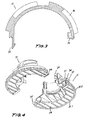
- Figure 4 is a perspective view of the semi-plate (11) faced with another semi-plate of same nature with joining possibilities through the tongues (35) and the cavities (36).
- Figure 5 is a perspective view of the wire-eye assembly (10) formed with the union of two semi-plates (11) over-moulded and surrounded by the over-moulded body (24).
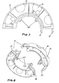
- Figure 6 is an elevation front view by the interior face of the semi-nut (12).
- Figure 7 is a plant bottom view of the semi-nut (12).
- Figure 8 is a perspective view of two semi-nuts (12) with joining possibilities through the tongues (27) to be fitted in the slits (28).
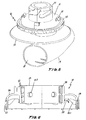
- Figure 9 is an elevation front view of the wire-eye assembly (10).
- Figure 10 is an elevation cross section of the wire-eye assembly (10) including the two semi-plates (11) and the two semi-nuts (12) once assembled and surrounding the over-moulded body (24).
- the wire-eye assembly (10) is formed by the union of two semi-plates (11), in such a way the the horizontal extension (37) and the interior crown (31) are covered by the over-moulded body (24), and at the same time, by means the over-moulding technique, is formed a cylindric zone (39) which inferior base extends horizontally as per a cylindric zone (40) of greater diameter wich extends downwards as per the rear plate (13) which in turn adopts the shape of a wrapping (19), being the wires introduced by the interior of the cylindric zone (39) and coming out from the wrapping (19) forming already the wires package (18), see Figure 10.
- over said over-moulded body (24) are mounted the semi-plates (11) which, as can be seen in Figures 1, 2, 3 and 4 shows an upper cylindric portion (17) which lower base extends as per an interior crown (31) which in turn extends to an exterior crown (32) which lower portion has the flange (32.1) whilst in the lateral surface of the exterior crown (32) shows at regular intervals the wings (32.2).
- the cylindric portion (17) of the semi-plate (11) is completed at the outside by thread ridges (34) and thread slits (22) allowing the assembly on said cylindric portion of a nut formed by semi-nuts (12).
- the semi-nuts (12), as can be seen in Figures 6, 7 and 8, are formed with a cylindric body (25) from which lateral surface extends a skirt (26) which exterior surface has recesses (30) whilst the interior portion of said skirt (26) is reinforced with ribs (26.1) and catches (29) which function is that of fitting in the pre-assembly clips (21).
- the interior lateral surface of the cylindric body (25) is provided with protrusions (25.1) whose function is that of fitting into the thread slits (22) of the semi-plates (11).
- the semi-nuts (12) are joined by the coupling of the tongues (27) into the slits (28), see Figures 6, 7 and 8.
- the wire-eye assembly is assembled as per the detail of the cross section shown in Figure 10, in which we can see how the nut is formed with semi-nuts (12) threads around the plate formed with semi-plates (11) with the help of the thread slits (22) found between the thread ridges (34), the protrusions (25.1) sliding through both, pressing the semi-plates against the over-moulded body (24), which covers the interior portion of the semi-plate (11), surrounding the wires (20), covering all its interior surfaces, fitting said over-moulded body (24) in the wall (41), in grace to the rear plate (13) which rests over the noise tightness gasket (14) pressing at the same time the wall (41), in such a way that the wires entering into the cylindric zone (39) come out through the cavity surrounded by the wrapping (19).
- the wire-eye assembly may also be formed by the over-moulded assembly (39, 23, 13) and a single portion plate and a single portion nut, with the same characteristics and configuration disclosed for the semi-plate (11) and the semi-nut (12). In some instances, it will be adopted the use of the plates formed on the basis of two semi-plates (11) and nuts formed by two semi-nuts (12) because it is easier to assembly.
Landscapes
- Engineering & Computer Science (AREA)
- Mechanical Engineering (AREA)
- Body Structure For Vehicles (AREA)
- Air-Conditioning For Vehicles (AREA)
- Installation Of Indoor Wiring (AREA)
Applications Claiming Priority (2)
| Application Number | Priority Date | Filing Date | Title |
|---|---|---|---|
| ES9802947U ES1041811Y (es) | 1998-11-23 | 1998-11-23 | Conjunto pasacables. |
| ES9802947U | 1998-11-23 |
Publications (3)
| Publication Number | Publication Date |
|---|---|
| EP1004480A2 true EP1004480A2 (fr) | 2000-05-31 |
| EP1004480A3 EP1004480A3 (fr) | 2003-09-24 |
| EP1004480B1 EP1004480B1 (fr) | 2006-05-31 |
Family
ID=8306473
Family Applications (1)
| Application Number | Title | Priority Date | Filing Date |
|---|---|---|---|
| EP19990500202 Expired - Lifetime EP1004480B1 (fr) | 1998-11-23 | 1999-11-02 | Dispositif d'oeillet pour câble |
Country Status (3)
| Country | Link |
|---|---|
| EP (1) | EP1004480B1 (fr) |
| DE (1) | DE69931581T2 (fr) |
| ES (1) | ES1041811Y (fr) |
Cited By (2)
| Publication number | Priority date | Publication date | Assignee | Title |
|---|---|---|---|---|
| EP2677615A3 (fr) * | 2012-06-18 | 2014-04-30 | Elastomer Solutions GmbH | Raccord |
| US20220130577A1 (en) * | 2020-10-28 | 2022-04-28 | Sumitomo Wiring Systems, Ltd. | Grommet |
Families Citing this family (2)
| Publication number | Priority date | Publication date | Assignee | Title |
|---|---|---|---|---|
| ES2158818B1 (es) * | 1999-12-07 | 2002-05-01 | Lear Automotive Eeds Spain | Procedimiento de inyeccion de pasacables y elemento centrador separador para utilizarlo con dicho procedimiento. |
| US9944239B1 (en) | 2017-05-19 | 2018-04-17 | Newfrey Llc | Fluid and dust resistant split grommet |
Family Cites Families (3)
| Publication number | Priority date | Publication date | Assignee | Title |
|---|---|---|---|---|
| JPH0266816A (ja) * | 1988-08-31 | 1990-03-06 | Yazaki Corp | グロメット |
| FR2701517B1 (fr) * | 1993-02-11 | 1995-05-05 | Peugeot | Agencement pour la fixation d'un élément allongé sur une paroi. |
| US5545854A (en) * | 1993-12-29 | 1996-08-13 | Yazaki Corporation | Grommet for wire sealing |
-
1998
- 1998-11-23 ES ES9802947U patent/ES1041811Y/es not_active Expired - Lifetime
-
1999
- 1999-11-02 DE DE69931581T patent/DE69931581T2/de not_active Expired - Lifetime
- 1999-11-02 EP EP19990500202 patent/EP1004480B1/fr not_active Expired - Lifetime
Non-Patent Citations (1)
| Title |
|---|
| None |
Cited By (3)
| Publication number | Priority date | Publication date | Assignee | Title |
|---|---|---|---|---|
| EP2677615A3 (fr) * | 2012-06-18 | 2014-04-30 | Elastomer Solutions GmbH | Raccord |
| US20220130577A1 (en) * | 2020-10-28 | 2022-04-28 | Sumitomo Wiring Systems, Ltd. | Grommet |
| US11817236B2 (en) * | 2020-10-28 | 2023-11-14 | Sumitomo Wiring Systems, Ltd. | Water blocking grommet for vehicle |
Also Published As
| Publication number | Publication date |
|---|---|
| ES1041811U (es) | 1999-08-01 |
| EP1004480A3 (fr) | 2003-09-24 |
| DE69931581D1 (de) | 2006-07-06 |
| DE69931581T2 (de) | 2007-05-10 |
| EP1004480B1 (fr) | 2006-05-31 |
| ES1041811Y (es) | 1999-12-16 |
Similar Documents
| Publication | Publication Date | Title |
|---|---|---|
| JP4384788B2 (ja) | スピーカの取付構造 | |
| US6995316B1 (en) | Overmolded wire sealing assembly | |
| US6264393B1 (en) | Connection unit between a support, specifically a body part of a motor vehicle and a plate element | |
| US5639993A (en) | Grommet | |
| US4685173A (en) | Grommet with angularly positionable tubular portion | |
| JPH1120573A (ja) | ワイヤハーネスの取付け構造 | |
| US20190017527A1 (en) | Sealed Fastener Clip with One-Step Assembly | |
| US5854452A (en) | System for fastening sheet materials together | |
| WO2000069687A1 (fr) | Ensemble de montage de haut-parleurs pour panneau de vehicule | |
| US7390969B2 (en) | Wire harness grommet | |
| EP0099115A2 (fr) | Structure d'auvent pour véhicule automobile | |
| EP1004480A2 (fr) | Dispositif d'oeillet pour câble | |
| US20150151608A1 (en) | Seat conditioning hood apparatus and method | |
| WO2005021334A1 (fr) | Tapis « dashmat » dote d'un pont de composant | |
| CN111746663A (zh) | 车轮罩构造 | |
| JPH11255042A (ja) | 自動車ドア用グロメットの取付構造 | |
| JP5765101B2 (ja) | グロメット | |
| JP4316365B2 (ja) | 留め具 | |
| JPH07249337A (ja) | グロメット | |
| CN106470879A (zh) | 安全带非扣合检测线缆的装配方法和装配环 | |
| JP3066948B2 (ja) | 自動車用ベルトラインモールディング | |
| JP3675116B2 (ja) | 配管取付装置 | |
| KR101478729B1 (ko) | 자동차의 벽에 내장된 전선 링 | |
| JP4036517B2 (ja) | 自動車用内装部品のクリップ取付座 | |
| US12586697B2 (en) | Grommet unit and waterproof structure |
Legal Events
| Date | Code | Title | Description |
|---|---|---|---|
| PUAI | Public reference made under article 153(3) epc to a published international application that has entered the european phase |
Free format text: ORIGINAL CODE: 0009012 |
|
| AK | Designated contracting states |
Kind code of ref document: A2 Designated state(s): AT BE CH CY DE DK ES FI FR GB GR IE IT LI LU MC NL PT SE |
|
| AX | Request for extension of the european patent |
Free format text: AL;LT;LV;MK;RO;SI |
|
| PUAL | Search report despatched |
Free format text: ORIGINAL CODE: 0009013 |
|
| AK | Designated contracting states |
Kind code of ref document: A3 Designated state(s): AT BE CH CY DE DK ES FI FR GB GR IE IT LI LU MC NL PT SE |
|
| AX | Request for extension of the european patent |
Extension state: AL LT LV MK RO SI |
|
| 17P | Request for examination filed |
Effective date: 20040312 |
|
| AKX | Designation fees paid |
Designated state(s): DE FR GB IT SE |
|
| 17Q | First examination report despatched |
Effective date: 20040906 |
|
| GRAP | Despatch of communication of intention to grant a patent |
Free format text: ORIGINAL CODE: EPIDOSNIGR1 |
|
| GRAS | Grant fee paid |
Free format text: ORIGINAL CODE: EPIDOSNIGR3 |
|
| GRAA | (expected) grant |
Free format text: ORIGINAL CODE: 0009210 |
|
| AK | Designated contracting states |
Kind code of ref document: B1 Designated state(s): DE FR GB IT SE |
|
| PG25 | Lapsed in a contracting state [announced via postgrant information from national office to epo] |
Ref country code: IT Free format text: LAPSE BECAUSE OF FAILURE TO SUBMIT A TRANSLATION OF THE DESCRIPTION OR TO PAY THE FEE WITHIN THE PRE;WARNING: LAPSES OF ITALIAN PATENTS WITH EFFECTIVE DATE BEFORE 2007 MAY HAVE OCCURRED AT ANY TIME BEFORE 2007. THE CORRECT EFFECTIVE DATE MAY BE DIFFERENT FROM THE ONE RECORDED.SCRIBED TIME-LIMIT Effective date: 20060531 |
|
| REG | Reference to a national code |
Ref country code: GB Ref legal event code: FG4D |
|
| REF | Corresponds to: |
Ref document number: 69931581 Country of ref document: DE Date of ref document: 20060706 Kind code of ref document: P |
|
| PG25 | Lapsed in a contracting state [announced via postgrant information from national office to epo] |
Ref country code: SE Free format text: LAPSE BECAUSE OF FAILURE TO SUBMIT A TRANSLATION OF THE DESCRIPTION OR TO PAY THE FEE WITHIN THE PRESCRIBED TIME-LIMIT Effective date: 20060831 |
|
| PLBE | No opposition filed within time limit |
Free format text: ORIGINAL CODE: 0009261 |
|
| STAA | Information on the status of an ep patent application or granted ep patent |
Free format text: STATUS: NO OPPOSITION FILED WITHIN TIME LIMIT |
|
| EN | Fr: translation not filed | ||
| 26N | No opposition filed |
Effective date: 20070301 |
|
| PG25 | Lapsed in a contracting state [announced via postgrant information from national office to epo] |
Ref country code: FR Free format text: LAPSE BECAUSE OF FAILURE TO SUBMIT A TRANSLATION OF THE DESCRIPTION OR TO PAY THE FEE WITHIN THE PRESCRIBED TIME-LIMIT Effective date: 20070309 |
|
| PG25 | Lapsed in a contracting state [announced via postgrant information from national office to epo] |
Ref country code: FR Free format text: LAPSE BECAUSE OF FAILURE TO SUBMIT A TRANSLATION OF THE DESCRIPTION OR TO PAY THE FEE WITHIN THE PRESCRIBED TIME-LIMIT Effective date: 20060531 |
|
| PGFP | Annual fee paid to national office [announced via postgrant information from national office to epo] |
Ref country code: DE Payment date: 20101126 Year of fee payment: 12 |
|
| PGFP | Annual fee paid to national office [announced via postgrant information from national office to epo] |
Ref country code: GB Payment date: 20101124 Year of fee payment: 12 |
|
| GBPC | Gb: european patent ceased through non-payment of renewal fee |
Effective date: 20121102 |
|
| REG | Reference to a national code |
Ref country code: DE Ref legal event code: R119 Ref document number: 69931581 Country of ref document: DE Effective date: 20130601 |
|
| PG25 | Lapsed in a contracting state [announced via postgrant information from national office to epo] |
Ref country code: DE Free format text: LAPSE BECAUSE OF NON-PAYMENT OF DUE FEES Effective date: 20130601 |
|
| PG25 | Lapsed in a contracting state [announced via postgrant information from national office to epo] |
Ref country code: GB Free format text: LAPSE BECAUSE OF NON-PAYMENT OF DUE FEES Effective date: 20121102 |