EP1004503A1 - Antriebsvorrichtung - Google Patents
Antriebsvorrichtung Download PDFInfo
- Publication number
- EP1004503A1 EP1004503A1 EP99203826A EP99203826A EP1004503A1 EP 1004503 A1 EP1004503 A1 EP 1004503A1 EP 99203826 A EP99203826 A EP 99203826A EP 99203826 A EP99203826 A EP 99203826A EP 1004503 A1 EP1004503 A1 EP 1004503A1
- Authority
- EP
- European Patent Office
- Prior art keywords
- pedal
- pedals
- flexible member
- propulsion apparatus
- frame
- Prior art date
- Legal status (The legal status is an assumption and is not a legal conclusion. Google has not performed a legal analysis and makes no representation as to the accuracy of the status listed.)
- Withdrawn
Links
- 230000005540 biological transmission Effects 0.000 claims description 8
- 230000000994 depressogenic effect Effects 0.000 claims description 3
- 230000035939 shock Effects 0.000 claims description 2
- 230000007704 transition Effects 0.000 claims description 2
- 230000001737 promoting effect Effects 0.000 claims 1
- 230000000712 assembly Effects 0.000 description 3
- 238000000429 assembly Methods 0.000 description 3
- 238000010276 construction Methods 0.000 description 3
- 229910000831 Steel Inorganic materials 0.000 description 1
- 230000006835 compression Effects 0.000 description 1
- 238000007906 compression Methods 0.000 description 1
- 239000002783 friction material Substances 0.000 description 1
- 239000000463 material Substances 0.000 description 1
- 239000010959 steel Substances 0.000 description 1
Images


Classifications
-
- B—PERFORMING OPERATIONS; TRANSPORTING
- B62—LAND VEHICLES FOR TRAVELLING OTHERWISE THAN ON RAILS
- B62M—RIDER PROPULSION OF WHEELED VEHICLES OR SLEDGES; POWERED PROPULSION OF SLEDGES OR SINGLE-TRACK CYCLES; TRANSMISSIONS SPECIALLY ADAPTED FOR SUCH VEHICLES
- B62M1/00—Rider propulsion of wheeled vehicles
- B62M1/24—Rider propulsion of wheeled vehicles with reciprocating levers, e.g. foot levers
- B62M1/28—Rider propulsion of wheeled vehicles with reciprocating levers, e.g. foot levers characterised by the use of flexible drive members, e.g. chains
Definitions
- This invention relates to manually powered propulsion apparatus.
- the invention has particular applicability to manually-powered cycles such as bicycles. With respect to the latter, the apparatus propels a bicycle through force exerted by a rider on pedals incorporated in the apparatus.
- the present invention also relates to manually-powered propulsion apparatus which may be employed to power a cycle wherein the pedals are operatively connected to the drive wheel of the cycle.
- manually-powered propulsion apparatus which may be employed to power a cycle wherein the pedals are operatively connected to the drive wheel of the cycle.
- the manually-powered propulsion apparatus of the present invention includes first and second pedals and pedal guide means.
- Mounting means mounts the pedals on the pedal guide means for reciprocating movement of the pedals between retracted and extended pedal positions.
- the apparatus also includes a first rotatable crank member and a second rotatable crank member mounted on a cycle frame along with a rotatable driver member.
- Pedal interconnecting means interconnects the first and second pedals and is operable to move one of the pedals to the retracted position thereof from the extended position thereof when the other of the pedals is depressed by a force applied thereto and moved to the extended position thereof from the retracted position thereof.
- Transmission means is operatively associated with the first and second pedals and the first and second rotatable crank members to transfer power alternatively from the first and second pedals through the first and second crank members to the rotatable driver member for imparting torque to the rotatable driver member responsive to alternate depression of the pedals along the pedal guide means from the retracted positions thereof to the extended positions thereof.
- the transmission means includes crank member engagement means attached to the pedal interconnecting means and in engagement with the crank members for rotating the crank members during movement of the pedal interconnecting means.
- a bicycle 10 incorporating apparatus of the present invention includes a frame 12 and wheels 14, 16. Wheel 14 is driven by a chain 18 connected to a conventional multi-sprocket gear assembly 15.
- Assembly 20 Connected to frame 12 by any suitable means is an assembly 20.
- Assembly 20 includes a housing 19 and bearings 21 (see Fig. 5).
- Rotatably journaled within housing 19 and bearings 21 is a sprocket shaft 23.
- a rotatable drive sprocket or driver member 22 is affixed to sprocket shaft 23 and extends adjacent to and outwardly of the housing 19.
- Drive sprocket or driver member 22 is of circular configuration and has teeth about the outer periphery thereof which engage chain 18.
- Member 22 is rotatable to drive the wheel 14 through the intermediate chain 18.
- first rotatable crank member 24 Located near the opposed ends of the assembly 20 are a first rotatable crank member 24 and a second rotatable crank member 26, the crank members being coaxial with the sprocket shaft 23.
- crank member 24 is shown in Fig. 1, however, as viewed in Fig. 1, clockwise rotation of either first rotatable crank member 24 or second rotatable crank member 26 will result in rotation of the driver member 22, the chain 18 and the wheel 14.
- crank members 24 and 26 are journaled on clutch and bearing assemblies 27, 29, respectively.
- the clutch and bearing assemblies can be of conventional construction and are illustrated diagrammatically. Rotation of the respective crank members 24, 26 clockwise (as viewed in Fig. 1) will cause rotation of sprocket shaft 23 and driver member 22 through the one-way clutches of assemblies 27, 29. However, the one-way clutches will allow ready counter-clockwise rotation of the crank members 24 and 26 without affecting movement of the sprocket shaft and driver member.
- Frame 12 of the bicycle includes two parallel frame members 32 which are in the form of channels defining interiors or trackways 36.
- frame member 32 In the interest of simplicity and clarity, only one such frame member 32 is illustrated, however it is to be understood that the other frame member 32 is of identical construction, the only difference being that it is located on the other side of the frame from that illustrated.
- My U.S. Patent No. 5,496,051 may be referred to for a teaching of the concept of employing two trackways disposed side-by-side to guide movement of two pedals of a cycle propulsion mechanism and the teachings of such patent are incorporated herein by reference.
- each frame member (see Figs. 4 and 4B) has parallel recesses 38 formed therein and extending the length thereof.
- Recesses 28 accommodate elongated rod-like members 39 formed of hard material such as steel or other suitable low friction material which will function as guides in the trackway for rollers 40 operatively associated with pedals employed in the apparatus in a manner which will now be described.
- Rollers 40 comprise portions of the mounting means employed to mount pedals 42, 44 to the rest of the apparatus.
- Pedals 42, 44 are connected to and project from the two pedal mount members 46, the pedals being rotatable on pedal mounting shafts 48 of the mount members.
- the rollers 40 allow the pedal mount members and pedals to freely move up and down along the trackways 36 of frame members 32.
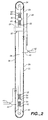
- elongated flexible member 50 Connected to each pedal through its associated pedal mount member is an elongated flexible member 50 which in the disclosed embodiment is an endless chain comprised of a plurality of pivotally interconnected chain link elements 52.
- chain 50 and other structure operatively associated therewith which will now be described have not been illustrated in Fig. 1. However, reference may be had to Figs. 2 through 4C in connection with the following description.
- Chain 50 forms a continuous loop about roller elements 54, 56.
- the roller elements are freely rotatably attached to opposed ends of a shaft 58.
- Shaft 58 passes through two bushings 60 which are in turn affixed to frame 12 of the bicycle in any suitable fashion.
- Flanges 62 are fixedly secured to shaft 58 on both sides of each bushing 60, as shown in Figs. 2 and 3.
- Four coil compression springs 64 are disposed between each flange 62 and its associated bushing 60.
- Chain 50 includes straight chain segments 66, 68.
- One of the pedal mount members 46 is affixed to chain segment 66 and the other affixed to chain segment 68. Depression of pedal 42 will cause clockwise rotation of chain 50 (as viewed in Fig. 2) and upward movement of pedal 44 and its associated mount member 46 to elevated or retracted position. Depression of the raised pedal 44 will similarly cause pedal 42 to return to its raised or retracted position due to rotation of the chain 50 in a counter clockwise direction as viewed in Fig. 2. The pedals move along parallel linear paths of movement. Springs 64 bias the shaft 58 toward a predetermined location relative to the frame 12 of the bicycle.
- Roller elements 54, 56 exert opposed forces on chain 50, the opposed forces being along an axis substantially parallel to the linear paths of movement of the pedals and associated mounting members.
- the chain segments 66, 68 are parallel to one another and to the linear paths of movement of the pedals and pedal mounts.
- the loop formed by chain 50 is movable and displaceable as a unit along with shaft 58 relative to the frame 12 along the axis of the opposed forces exerted on chain 50 by the roller elements responsive to forces applied to the pedals. This is for the purpose of absorbing shock applied to the chain caused by alternate depression of the pedals and a smooth transition between the pedals during operation of the apparatus is promoted thereby.
- Chain segments 66, 68 pass through a gap formed between rotatable crank members 24, 26 and guide or backing rollers 70 rotatably mounted on frame 12.
- Each crank member includes a crank member body 72 having attached thereto at the outer periphery thereof by any suitable expedient spaced side plates 74.
- stub shafts or rollers 76 Extending between side plates 74 and rotatably mounted thereon are double-ended stub shafts or rollers 76. As may perhaps best be seen with reference to Fig. 4, the stub shafts or rollers 76 are received in receptacles 80 affixed to chain 50 at spaced locations thereon. Some of the stub shafts 76 are always received in some of the receptacles. Thus, movement of chain 50 in either a clockwise or counter-clockwise direction will cause rotation of the crank members 24, 26. One crank member will rotate clockwise during movement of the chain and the other counter-clockwise, it being apparent that the direction of rotation of a particular crank member will depend upon the direction of movement of the chain segment to which it is releasably connected.
Landscapes
- Engineering & Computer Science (AREA)
- Chemical & Material Sciences (AREA)
- Combustion & Propulsion (AREA)
- Transportation (AREA)
- Mechanical Engineering (AREA)
- Transmission Devices (AREA)
Applications Claiming Priority (2)
| Application Number | Priority Date | Filing Date | Title |
|---|---|---|---|
| US09/198,916 US6113510A (en) | 1998-09-08 | 1998-11-24 | Propulsion apparatus |
| US198916 | 1998-11-24 |
Publications (1)
| Publication Number | Publication Date |
|---|---|
| EP1004503A1 true EP1004503A1 (de) | 2000-05-31 |
Family
ID=22735429
Family Applications (1)
| Application Number | Title | Priority Date | Filing Date |
|---|---|---|---|
| EP99203826A Withdrawn EP1004503A1 (de) | 1998-11-24 | 1999-11-17 | Antriebsvorrichtung |
Country Status (3)
| Country | Link |
|---|---|
| US (1) | US6113510A (de) |
| EP (1) | EP1004503A1 (de) |
| CN (1) | CN1256224A (de) |
Cited By (1)
| Publication number | Priority date | Publication date | Assignee | Title |
|---|---|---|---|---|
| AT409755B (de) * | 2000-09-27 | 2002-11-25 | Hickmann Guenther Dipl Ing | Fahrrad mit kettenantrieb |
Families Citing this family (4)
| Publication number | Priority date | Publication date | Assignee | Title |
|---|---|---|---|---|
| CN1245305C (zh) * | 2002-06-17 | 2006-03-15 | 钱祖凡 | 牵动式直线往复驱动器 |
| US8840127B2 (en) | 2012-01-04 | 2014-09-23 | Robert Musgrove | Spiral cone pulley reciprocal pedal drive system and methods |
| CN207089571U (zh) * | 2017-06-05 | 2018-03-13 | 上海昶意机械制造有限公司 | 一种双踏板驱动的滑板车 |
| US10882586B2 (en) * | 2018-10-25 | 2021-01-05 | Shenzhen Nanbo Automation Equipment Co., Ltd. | Transmission structure for bicycle |
Citations (2)
| Publication number | Priority date | Publication date | Assignee | Title |
|---|---|---|---|---|
| DE4027925A1 (de) * | 1990-09-04 | 1991-01-17 | Anton Schad | Muskelkraft-pedalantrieb zur umwandlung einer geradlinigen hin- und hergehenden, bzw. auf- und abgehenden bewegung in eine drehbewegung zum erreichen einer maximalen kraftuebertragung |
| US5496051A (en) | 1994-04-15 | 1996-03-05 | Farmos; George T. | Apparatus for propelling a manually-powered cycle |
Family Cites Families (6)
| Publication number | Priority date | Publication date | Assignee | Title |
|---|---|---|---|---|
| US3132877A (en) * | 1962-04-04 | 1964-05-12 | Fernando A Pontin | Bicycle propulsion means |
| US3891235A (en) * | 1974-07-02 | 1975-06-24 | Cordova James De | Bicycle wheel drive |
| US4169609A (en) * | 1978-01-26 | 1979-10-02 | Zampedro George P | Bicycle wheel drive |
| US5104137A (en) * | 1990-10-29 | 1992-04-14 | Kilts Gary R | Apparatus and method for providing rotary power |
| US5236211A (en) * | 1991-02-08 | 1993-08-17 | Ohannes Meguerditchian | Drive system |
| US5690345A (en) * | 1995-10-03 | 1997-11-25 | Kiser; David Kerry | Bicycle pedal that moves in a rectilinear path |
-
1998
- 1998-11-24 US US09/198,916 patent/US6113510A/en not_active Expired - Fee Related
-
1999
- 1999-11-17 EP EP99203826A patent/EP1004503A1/de not_active Withdrawn
- 1999-11-24 CN CN99125806.1A patent/CN1256224A/zh active Pending
Patent Citations (2)
| Publication number | Priority date | Publication date | Assignee | Title |
|---|---|---|---|---|
| DE4027925A1 (de) * | 1990-09-04 | 1991-01-17 | Anton Schad | Muskelkraft-pedalantrieb zur umwandlung einer geradlinigen hin- und hergehenden, bzw. auf- und abgehenden bewegung in eine drehbewegung zum erreichen einer maximalen kraftuebertragung |
| US5496051A (en) | 1994-04-15 | 1996-03-05 | Farmos; George T. | Apparatus for propelling a manually-powered cycle |
Cited By (1)
| Publication number | Priority date | Publication date | Assignee | Title |
|---|---|---|---|---|
| AT409755B (de) * | 2000-09-27 | 2002-11-25 | Hickmann Guenther Dipl Ing | Fahrrad mit kettenantrieb |
Also Published As
| Publication number | Publication date |
|---|---|
| US6113510A (en) | 2000-09-05 |
| CN1256224A (zh) | 2000-06-14 |
Similar Documents
| Publication | Publication Date | Title |
|---|---|---|
| US3759543A (en) | Variable speed lever action bicycle drive | |
| EP0752950B1 (de) | Vorrichtung zum antreiben von fahrrädern | |
| US4479660A (en) | Two wheel synchronously driven bicycle | |
| EP2193068B1 (de) | Fahrzeug und dessen muskelgetriebener antriebsmechanismus | |
| US4169609A (en) | Bicycle wheel drive | |
| US4574649A (en) | Propulsion and speed change mechanism for lever propelled bicycles | |
| US6000707A (en) | Linear driving apparatus | |
| JPS6229483A (ja) | レバ−推進自転車用推進機構 | |
| US6129646A (en) | Apparatus for propelling a cycle | |
| US4026571A (en) | Bicycle with rear mounted crank arms and improved chain control unit | |
| US20140251709A1 (en) | Vehicle having a pedal drive and a reverse gear mechanism | |
| US4353569A (en) | Freewheel flywheel transmission system | |
| US6123635A (en) | Propulsion apparatus for a cycle | |
| US6113510A (en) | Propulsion apparatus | |
| US6123636A (en) | Propulsion apparatus | |
| US7896377B2 (en) | Lever enhanced pedaling system with multi-speed control system | |
| AU1086999A (en) | Linear driving apparatus | |
| US11142218B2 (en) | Suspended recreational vehicle drive | |
| US6916031B1 (en) | Frictionless bicycle stopping device | |
| WO2001021473A1 (en) | Length varying device for pedal arms of bicycle | |
| RU2122958C1 (ru) | Велосипед реечный | |
| KR100789888B1 (ko) | 체인리스 자전거 | |
| SU1177197A1 (ru) | Транспортное средство,приводимое в действие мускульной силой человека | |
| KR20230103549A (ko) | 로프식 전기 자전거 | |
| KR930007285Y1 (ko) | 자전차 페달의 수직작동 장치 |
Legal Events
| Date | Code | Title | Description |
|---|---|---|---|
| PUAI | Public reference made under article 153(3) epc to a published international application that has entered the european phase |
Free format text: ORIGINAL CODE: 0009012 |
|
| AK | Designated contracting states |
Kind code of ref document: A1 Designated state(s): AT BE CH CY DE DK ES FI FR GB GR IE IT LI LU MC NL PT SE |
|
| AX | Request for extension of the european patent |
Free format text: AL;LT;LV;MK;RO;SI |
|
| AKX | Designation fees paid |
Free format text: AT BE CH CY DE DK ES FI FR GB GR IE IT LI LU MC NL PT SE |
|
| STAA | Information on the status of an ep patent application or granted ep patent |
Free format text: STATUS: THE APPLICATION IS DEEMED TO BE WITHDRAWN |
|
| 18D | Application deemed to be withdrawn |
Effective date: 20001201 |