EP1004506B1 - Mit dünnen Seilen befestigter Block - Google Patents
Mit dünnen Seilen befestigter Block Download PDFInfo
- Publication number
- EP1004506B1 EP1004506B1 EP99122977A EP99122977A EP1004506B1 EP 1004506 B1 EP1004506 B1 EP 1004506B1 EP 99122977 A EP99122977 A EP 99122977A EP 99122977 A EP99122977 A EP 99122977A EP 1004506 B1 EP1004506 B1 EP 1004506B1
- Authority
- EP
- European Patent Office
- Prior art keywords
- head
- passage
- locking
- central hub
- sidewalls
- Prior art date
- Legal status (The legal status is an assumption and is not a legal conclusion. Google has not performed a legal analysis and makes no representation as to the accuracy of the status listed.)
- Expired - Lifetime
Links
- 239000002657 fibrous material Substances 0.000 claims description 24
- 229920002430 Fibre-reinforced plastic Polymers 0.000 claims description 2
- 239000011151 fibre-reinforced plastic Substances 0.000 claims description 2
- 229920001169 thermoplastic Polymers 0.000 claims description 2
- 239000002184 metal Substances 0.000 description 11
- 238000010276 construction Methods 0.000 description 4
- 239000000835 fiber Substances 0.000 description 4
- 230000013011 mating Effects 0.000 description 4
- 238000004873 anchoring Methods 0.000 description 3
- 239000000463 material Substances 0.000 description 3
- 239000004033 plastic Substances 0.000 description 3
- 229920003023 plastic Polymers 0.000 description 3
- XLYOFNOQVPJJNP-UHFFFAOYSA-N water Substances O XLYOFNOQVPJJNP-UHFFFAOYSA-N 0.000 description 3
- 238000010521 absorption reaction Methods 0.000 description 2
- 239000002131 composite material Substances 0.000 description 2
- 229920000271 Kevlar® Polymers 0.000 description 1
- 229910000831 Steel Inorganic materials 0.000 description 1
- 229920001494 Technora Polymers 0.000 description 1
- 229920000508 Vectran Polymers 0.000 description 1
- 239000004979 Vectran Substances 0.000 description 1
- 229920006231 aramid fiber Polymers 0.000 description 1
- 238000003780 insertion Methods 0.000 description 1
- 230000037431 insertion Effects 0.000 description 1
- 239000004761 kevlar Substances 0.000 description 1
- 239000003562 lightweight material Substances 0.000 description 1
- 230000014759 maintenance of location Effects 0.000 description 1
- 238000000034 method Methods 0.000 description 1
- 239000000203 mixture Substances 0.000 description 1
- 238000012986 modification Methods 0.000 description 1
- 230000004048 modification Effects 0.000 description 1
- 239000002991 molded plastic Substances 0.000 description 1
- 229920000728 polyester Polymers 0.000 description 1
- 229920000098 polyolefin Polymers 0.000 description 1
- 230000000717 retained effect Effects 0.000 description 1
- 238000009958 sewing Methods 0.000 description 1
- 238000001228 spectrum Methods 0.000 description 1
- 239000010959 steel Substances 0.000 description 1
- 239000004950 technora Substances 0.000 description 1
Images


Classifications
-
- B—PERFORMING OPERATIONS; TRANSPORTING
- B63—SHIPS OR OTHER WATERBORNE VESSELS; RELATED EQUIPMENT
- B63H—MARINE PROPULSION OR STEERING
- B63H9/00—Marine propulsion provided directly by wind power
- B63H9/04—Marine propulsion provided directly by wind power using sails or like wind-catching surfaces
- B63H9/08—Connections of sails to masts, spars, or the like
- B63H9/10—Running rigging, e.g. reefing equipment
-
- B—PERFORMING OPERATIONS; TRANSPORTING
- B66—HOISTING; LIFTING; HAULING
- B66D—CAPSTANS; WINCHES; TACKLES, e.g. PULLEY BLOCKS; HOISTS
- B66D3/00—Portable or mobile lifting or hauling appliances
- B66D3/04—Pulley blocks or like devices in which force is applied to a rope, cable, or chain which passes over one or more pulleys, e.g. to obtain mechanical advantage
Definitions
- the present invention relates to a bearing block wherein the block has tethering means for attachment to a boat or the like.
- Bearing blocks are commonly used on sailboats for controlling and changing the direction of lines, to provide a mechanical advantage, or otherwise adjust the rigging. These blocks must be anchored to fixtures on the boat, such as padeyes, eyestraps, u-bolts, booms, and the like. Blocks are typically anchored to the fixtures by use of metal shackles, or by using a length of strap or webbing. Various disadvantages are associated with each of these anchoring configurations.
- Anchoring a block by use of a metal shackle may require the use of a substantial shackle piece with an associated substantial weight.
- the metal shackle is rigid and not compact. Lightweight components are preferred for sailboats, particularly for performance type sailboats.
- block anchor configurations utilizing a length of strap or webbing have been developed. These configurations offer comparable strength to metal anchors with the advantage of being significantly lighter.
- webbed or strapped configurations provide a lower profile block than a metal anchor can.
- JP 11 22 796 discloses a bearing block according to the preamble of claims 1 and 14.
- Said bearing block comprises a projecting portion with two grooves for removably locking the ends of a length of fibrous material.
- GB 172 753 discloses a pulley according the preamble of claims 12 and 13.
- the ends of an axle of the pulley-sheave project through the side-cheeks and are provided with guards which hold in position the loops of an endless wire-strop.
- the wire-strop passes through a distance-piece, and its upper loops pass over saddles on a thimble.
- DE 33 49 90 discloses a bearing block according the preamble of claims 24 and 25. In this construction a continuous rope is looped through the central hub of the bearing block.
- the present invention generally comprises a bearing block having a head, a center hub connected to said head, bearing means, and sheave means, with the bearing means facilitating rotation of the sheave about the center hub.
- the block of the invention further comprises means for removably attaching and locking in place end portions of a length of high strength fibrous material, preferably rope or cordage, to the block, with the center portion of the length thereby forming a loop for tethering the block to a boat deck or like location.
- the block of the invention is preferably comprised of lightweight, high strength plastic.
- the head and the central hub of the block each have a passage. End portions of the high strength fibrous material, preferably rope or cordage, are looped through the head passage and through the central hub passage.
- this preferred block offers various advantages of having the tethering load carried within the sheave.
- the block cheeks and head may then be constructed of lighter weigh materials as they are not required to carry significant loads.
- the load will be effectively captured and retained by the tethering loop passing through the sheave.
- the rope ends may be removably locked in place proximate to the central hub passage by tying a stop knot or by otherwise fitting the cord end so that it will not be able to pass back through the passage.
- the block of the invention further comprises locking means for removably locking the cordage in place.
- Preferred cord locking means comprise an adjustable set screw that extends tangentially into the passage through a passage sidewall for removably locking the rope in place.
- the block sheave preferably has a passage through which a screwdriver, Allen wrench, or other suitable tool may be extended to adjust the bolt head.
- the central hub has a first passage that is larger than a plurality of secondary central hub passages.
- the rope may be looped through the head passage and larger first passage a number of times, and then laced through each of the secondary passages a single time. Because the larger first hub passage contains several passes of the cord, the amount of load that the block may bear is much larger than would be allowed by a single cord.
- the rope ends may be knotted or otherwise configured to prevent them from passing back through a passage.
- at least one of the plurality of passages, and preferably two, comprise the set screw locking means described above for removably locking the rope in place.
- other embodiments comprise a block having cord locking means within the block head or side cheeks.
- the high strength fibrous material of the invention preferably comprises small diameter cords and ropes with low stretch and low water absorption. It has been discovered that the block of the invention comprising these preferred cords and ropes provides a lighter weight block that eliminates the need for metal shackles, u-bolts, or other heavy structure tethering devices.
- the preferred cords are of small diameter, have good flexibility, and are thus easy to work with and give the block some ability to twist and auto-align with loads.
- the cords also have high tensile strength, thus providing the block of the invention with required load bearing strength.
- the various embodiments of the block of the invention thus provide a lightweight block with high tensile tethering strength that eliminates the need for metal shackles, u-bolts, or other heavy structure devices for tethering it to a boat deck or the like. Also, there is no need to sew webbing in place for block tethering.
- the block of the invention may be easily removed and re-tethered.
- the cord may be easily cinched up tight to bring the block of the invention to an advantageous low position on the deck or other article to which it is tethered.
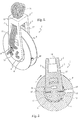
- Fig. 1 is a perspective view of a preferred embodiment of the block of the invention.
- Fig. 2 is an elevational side view, shown partly in cross section, of the preferred embodiment of the block of the invention.
- Fig. 3 is an elevational front view, shown partly in cross section, of the preferred embodiment of the block of the invention.
- Fig. 4 is the same elevational front view as shown in Fig. 3 of the preferred embodiment of the block of the invention, with cord.
- Fig. 5A is a side elevational view, partly in cross section, of a second example block of the invention.
- Fig. 5B is an end elevational view of the block of Fig. 5A.
- Fig. 5C is a top plan view of the block of Fig. 5A.
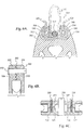
- Fig. 6A is a side elevational view, partly in cross section, of the top portion of a third example block of the invention.
- Fig. 6B is an end elevational view, partly in cross section, of the top portion of the block of Fig. 6A.
- Fig. 6C is a top plan view in partial cross section of the block of Fig. 6A.
- Fig. 7A is a perspective view of a fourth example block embodiment of the invention.
- Fig. 7B is an end elevational view, partly in cross section, of the top portion of the block of Fig. 7A.
- Fig. 7C is a side elevations view of the block of Fig. 7A.
- Fig. 8A is a perspective view of a fifth example embodiment of the block of the invention.
- Fig. 8B is a perspective view of one sidewall of the block of Fig. 8A.
- Fig. 9A is a side elevational view, partly in cross section, of a sixth example embodiment of the block of the invention.
- Fig. 9B is an end elevational view, partly in cross section, of the block of Fig. 9A.
- Fig. 9C is a side elevational view of the strap of the block of Fig. 9A.
- Fig. 9D is a side elevational view of the strap of the block of Fig. 9A.
- Fig. 9E is a perspective view of the block of Fig. 9A with the strap in a first orientation.
- Fig. 9F is a perspective view of the block of Fig. 9A with the strap in a second orientation.
- Fig. 10A is a perspective view of an eighth example block embodiment of the invention.
- Fig. 10B is a side elevational cross sectional view of the top portion of block of Fig. 11A.
- Fig. 10C is an end elevational cross sectional view of the top portion of the block of Fig. 10A.
- Fig. 10D is a top plan view of the top portion of the block of Fig. 10A.
- FIG. 1 shows a perspective view of a preferred block of the invention.
- Block 1 comprises head 2 with arms 3 connected to central hub 4.
- Ball bearings 6 facilitate rotation of annular sheave 8 about central hub 4.
- Central hub 4 has a first axial passage 10, and a plurality of smaller secondary axial passages 12.
- Head 2 also has passage 14.
- Passages 10, 12 and 14 are for passing and retaining high strength cord 15 for tethering block 1.
- Cord 15 is looped several times through head passage 14 and central hub first passage 10, with cord 15 ends laced through central hub secondary passages 12, where they will be removably locked in place.
- Cross member 17 connects side arms 3, with cord 15 passing over cross member 17 so as to avoid interference with the rotation of sheave 8.
- Preferred cord 15 comprises a low stretch, low creep, and low water absorption cord of multiple intertwined thermoplastic polymer filament composition.
- Core as used herein is intended to be interchangeable with the term "rope”.
- the preferred ropes are generally made with a high strength fiber core, and a braided jacket of softer material, such as polyester. Materials of construction for the core of the preferred cord include, but are not limited to, Kevlar, a DuPont trade name for an aramid fiber, and Spectra, an Allied Signal trade name for polyolefin fibers.
- preferred block embodiment of the invention comprises a block for use on small boats, preferred cord diameters are generally between 1/8 inch and 1 ⁇ 2 inch.
- the block of the invention would not be practical for many applications without use of such high tech cords that combine high tensile strength with a small diameter.
- the invention could not be practiced in a manner suitable for use in sailing, for instance, using cords comprised of organic fibers due to the diameter of cord required to achieve required tensile strength.
- preferred cords include several available from the Yale Cordage Co., Biddeford ME; including Crystalyne, Vectrus 12, Aracom-T, Aramid-T, and Light.
- Other commercial examples include several cords available from the New England Rope Co., Fall River MA; including T-900, Spect-set II, Sta-set, and Sta-set X.
- Still other commercial examples include Technora and Vectran.
- the tensile strength of the rope will of course vary with application.
- the preferred block of the invention allows for lashing with multiple strands, so that the total strength of the tethering line may be a multiple of its tensile strength.
- Fig. 2 is a side elevational view of the preferred embodiment of bearing block 1 of the invention, shown without cord 15.
- Fig. 2 also illustrates block 1 comprised of head 2 with arms 3 connected to central hub 4.
- Ball bearings 6 facilitate rotation of annular sheave 8 about central hub 4.
- Central hub 4 has a first axial passage 10, and a plurality of smaller secondary axial passages 12.
- Head 2 also has passage 14. These passages are for passing high strength cord 15 of Fig. 1 for tethering block 1, with the cord looped several times through head passage 14 and central hub first passage 10, and the cord ends then laced through central hub secondary passages 12.
- Fig. 2 also illustrates preferred locking means of set screws 16 for locking in place cord 15 ends in two secondary passages 12.
- Set screws 16 extend into two of secondary passages 12 for compressing against cord 15.
- Set screw 16 has a head for adjustment which is accessible through sheave passage 20 (also illustrated in Fig. 1). Sheave 8 may be rotated to a position where passage 20 is proximate one or the other of set screws 16 for adjustment thereof.
- cord 15 is present in secondary passage 12 with set screw 16
- set screw 16 may be tightened, thereby forcing it downward into passage 12 and compressing against cord 15.
- set screw 16 may be counter adjusted to retract it from passage 12, thereby releasing cord 15.
- set screw 16 head resides between two annular rings of bearings 6, in annular alignment with sheave passage 20.
- Fig. 3 also illustrates that ball bearings 6 comprise a first set 22 and a second set 24.
- Sheave 8 has a first annular race 25 and a second annular race 26, while central hub has a first annular race 27 and second annular race 28.
- First set of ball bearings 22 is rotatably engaged between race 25 and 27, with second set of ball bearings 24 rotatably engaged between race 26 and 28.
- Set screw 16 head is located between first set of annular bearings 22 and second set 24.
- the elevational partial cross section of Fig. 3 also illustrates the axial nature of central hub first passage 10 and secondary passages 12, with set screw 16 extending into two of secondary passages 12.
- the present invention is not limited to locking means comprising set screws 16 as illustrated in Fig. 2.
- the present invention as recited in the attached claims also comprises embodiments that removably lock cord 15 in place by use of stop knots, including by way of example a figure eight knot or a over-hand knot, tied in the cord ends to prevent the cord from passing through central hub passages 10 or 12.
- stop knots including by way of example a figure eight knot or a over-hand knot, tied in the cord ends to prevent the cord from passing through central hub passages 10 or 12.
- Other suitable means as are known in the art may likewise be comprised within the scope of the appended claims.
- Fig. 4 illustrates the same view as Fig. 3, with preferred cord 15 of the invention in place.
- Cord 15 is passed a plurality of times through head passage 14 and central hub first axial passage 10, creating loop 32 for tethering block 1 to an eye strap or other attachment point on a boat deck.
- Loop 32 comprises a plurality of individual loops of cord 15.
- Cord 15 has its ends laced through central hub secondary passages 12, with the ends finally removably locked in place in secondary passages 12 by set screws 16.
- one end of cord 15 may be locked in place in a secondary passage 12 with set screw 16.
- the second end of cord 15 is then laced through secondary passages 12, and looped a plurality of times through hub first passage 10 and head passage 14 and around a eye strap, boom, or other attachment point to which block 1 is to be tethered to.
- the second end of cord 15 is then laced through remaining secondary passages 12, drawn to a desired tension, and locked in place in secondary passage 12 with the second set screw 16.
- the preferred block of the invention when constructed of lightweight molded plastic composites, and when using preferred cords as generally described above, achieves suitable working load capacities when using either the preferred locking set screw means or a tied stop knot. Further, the preferred block achieved a weight savings of 21% over a prior art block of the same size.
- FIG. 5A is a side elevational view, partly in cross section, of block 100, which generally comprises side cheek 102, central hub 104, head 106, and sheave 108 rotatably mounted about central hub 104.
- a substantially vertical slot 110 (shown in broken line) extends through head 106, with cross pin 112 extending substantially horizontally through slot 110.
- Slot 110 has first side 114, and second side 116.
- a substantially horizontal passage intersects slot 110, with a first length 118 connecting to slot first side 114, and a second length 120 connecting to slot second side 116 (both lengths shown in broken line).
- a length of high strength cord 122 has a first end portion 124 and a second end portion 126 extended through slot 110.
- Cord first end portion 124 passes along slot first side 114, by a first side of cross pin 112, then crosses slot 110 to exit head 106 through horizontal passage second length 120.
- cord second end portion 126 passes along slot second side 116 by a second side of cross pin 112, then crosses slot 110 to exit head 106 through horizontal passage first length 118.
- cross pin 112 allows for the load on line end portions 124 and 126 to be well distributed, and advantageously prevents end portions 124 and 126 from contacting a sharp edge under load.
- An overall lighter weight head is also allowed for, as the load is concentrated on cross pin 112.
- a resilient post 112 comprised of steel, for instance, may be combined with a relatively lightweight block head 106.
- FIG. 5B illustrates an end elevational view of block 100, with preferred threaded set screw 128 extending into passage length 120 for locking the cord in place.
- set screw 128 of Fig. 5B extends through hole 130.
- a second screw extends through hole 132 into passage 118 to likewise lock cord second end portion 126 in place.
- stop knots may of course be tied in cord end portions 124 and 126 to removably lock them in place.
- Fig. 5C shows a top plan view of block 100, with several passes of cord 122 comprised for additional tethering strength.
- Fig. 5C also illustrates cross pin 112 extending our of block head 106, with a retaining pin 133 placed through it for retention.
- FIG. 6A illustrates a side elevational view, partly in cross section, of the top portion of block 500 of the invention.
- Block 500 generally comprises head 502, side cheeks 504, as well as a sheave rotatably mounted about a central hub (sheave and hub not illustrated).
- Head 502 has a substantially vertical slot 504 with a first side 506 and a second side 508.
- a cross pin 510 extends horizontally through slot 504.
- a first locking path 512 intersects with slot first side 506 below cross pin 510, with a second locking path 514 intersecting slot second side 508 also below cross pin 510.
- a cord 516 has a first end portion 518 passed along slot first side 506, wrapped around the bottom of cross pin 510, and extended along second locking path 514.
- Cord 516 has second end 520 which passes along slot second side 508, wraps around under cross pin 510, and extends along first locking path 512.
- block head 502 has two sidewalls 522 and 524, with each having interengaging ridged inner walls 526 and 528.
- adjustable locking screws 530 may be used to urge block head sidewalls 522 and 524 together. As this occurs, ridged interengaging inner walls 526 and 528 compress against and thereby resiliently engage cord end portions 518 and 520 in locking paths 514 and 512, respectively.
- a cord center portion 532 thereby forms a loop for tethering block 500.
- Block 150 has head 151, cheeks 152 connecting a central hub 154, with a sheave 156 rotatably mounted about the central hub. Bearing means (not illustrated) facilitate rotation of sheave 156 about hub 154.
- Head 151 has two sidewalls 158, with a slot formed therebetween. Sidewalls 158 each have inside surfaces 160 a plurality of locking ridges.
- Two adjustable threaded locking screws 162 are for urging sidewalls 158 towards one another.
- a central locking member 164 is contained within the slot between sidewalls 158.
- Central locking member 164 has two outside walls 166 that oppose sidewall inside surfaces 160.
- Locking member outside walls 166 have a plurality of locking ridges on them.
- a length of cord 168 is removably locked in place within head 151 by having its ends wrapped about central locking member 164, with sidewalls 158 then compressed towards one another and cord 168 end portions thereby removably locked in place between sidewall inside surfaces 160 and locking member outside walls 166.
- Fig. 7B illustrates block head 151 from an end cross section view. Sidewalls 158 have ridged inside surfaces 160 in opposition to locking member 164 outside walls 166. Fig. 7B also illustrates first sidewall passage 170, central locking member passage 172, and second sidewall passage 174. Locking screw 162 passes freely through second sidewall passage 174, freely through central locking member passage 172, and is threadably received in first sidewall passage 170, to thereby urge sidewalls 158 towards central locking member 164. In addition to being threadably received, locking screw 162 could of course be fastened with a nut, or as otherwise may be known.
- FIG. 7C illustrates a side elevational view of the upper portion of block 150, showing both locking screws 162.
- FIG. 8A and 8B illustrate perspective views of a block embodiment similar to that illustrated in Figs. 7A-7C.
- block 200 upper portion has head 202, with two opposing sidewalls 204 and 206 urged towards one another by locking screws 208.
- a substantially vertical slot 209 is formed in head 202, with slot halves defined by recessed portions of sidewalls 204 and 206.
- a length of cord 210 has its ends removably locked in place in slot 209 between sidewalls 204 and 206, with a center portion of cord 210 thereby forming a loop (not illustrated) for tethering block 200.
- Fig. 8B illustrates a perspective view of the upper portion of sidewall 206 without central locking member 164.
- Passages 212 for receiving locking screws 208 of Fig. 8A are shown.
- Sidewall recessed portion 214 is also illustrated, which define half of slot 209.
- a plurality of locking ridges 216 or teeth are comprised along the surface of recessed portion 214 for enhanced gripping of cord 210 of Fig. 8A.
- Block 250 generally comprises a head 252, side cheeks 254 connecting a central hub 256, and a sheave 258 rotatably mounted about hub 256.
- a first passage 260 (shown in dashed line) connects the two head endwalls 262.
- a locking screw 264 extends downward from the head top 266, and connects with spring 268 and sleeve press 270. Upon downward adjustment, locking screw 264 may extend sleeve press 270 downward into passage 260 to lock in place a strap extended through passage 260.
- Spring 268 operates to retract sleeve press 270 upon retraction of screw 264 to thereby clear passage 260 for insertion (or removal) of a strap.
- Fig. 9B illustrates an elevational end view of block 250.
- Fig. 9B also shows a second passage 272 which extends through head 262 substantially perpendicular to first passage 260.
- Second passage 272 connects opposing sidewalls 274 of head 264.
- Second passage 272 and first passage 260 intersect near their centers, under sleeve press 270. In this manner sleeve press 270 may be used to compress against a strap in either first passage 260 or second passage 272.
- Figs. 9C and 9D offer two views of strap 276 appropriate for use with block 250.
- Strap 276 is preferably comprised of fiber reinforced plastic.
- Fig. 9C shows strap 276 having first and second end portions 278 and 280; each having a plurality of cooperating mating teeth, 282 and 284 respectively, on their surface.
- strap is looped through block 250, with the respective sets of mating teeth 282 and 284 interengaging one another as generally shown in Fig. 9D.
- the respective teeth sets 282 and 284 are interengaged within passage 272 or 260, with screw 264 and sleeve 270 firmly compressing against strap 276 for strong interengagement.
- other strap configurations may comprise mating fiber hook and loop sets of the sort commonly known as "Velcro".
- Figs. 9E and 9F illustrate strap 276 inserted in first passage 260 and second passage 272, respectively.
- One or the other orientation may be desirable to achieve a desired tethering configuration.
- Block 350 generally comprises head 352, side cheeks 354, central hub 356, and sheave 358 rotatably mounted about central hub 356.
- Head 352 has sidewalls 360 separated by a pair of transverse locking posts 362.
- a continuous loop of high strength cord 364 is threaded about locking posts 362 to form a locked in place tethering loop.
- Head sidewalls 360 are held together by a pair of locking screws 366 which extend through locking posts 362. To thread continuous loop 364, screws 366 may be removed to remove or separate sidewalls 360 for access to locking posts 362.
- Fig. 10B shows a side cross sectional view of posts 362 with one sidewall 360 removed, and continuous loop 364 threaded thereon.
- Fig. 10C shows an end cross sectional view with locking screw 366 extending through sidewalls 360 and locking post 362.
- Fig. 10D shows a top plan cross sectional view of head 352, also with locking screws 366 extending through sidewalls 360 and locking posts 362.
- the screws or bolts may be threaded directly into the plastic block sidewall.
- a threaded metal insert may be provided within the screw passage for receiving the screw. This may provide additional strength.
- Another means of joining sidewalls with a screw comprises a passage that is not threaded, with a threaded nut receiving the screw end exterior to the passage.
Landscapes
- Engineering & Computer Science (AREA)
- Mechanical Engineering (AREA)
- Life Sciences & Earth Sciences (AREA)
- Sustainable Development (AREA)
- Sustainable Energy (AREA)
- Chemical & Material Sciences (AREA)
- Combustion & Propulsion (AREA)
- Ocean & Marine Engineering (AREA)
- Ropes Or Cables (AREA)
Claims (25)
- Mit einer Länge eines faserigen Materials hoher Festigkeit kombinierter Block (500; 150), der einen Kopf (502;151), ein Paar Seitenwangen (504;152), eine zentrale Nabe (154), die mit dem Kopf durch die Seitenwangen verbunden ist, eine Rolle (156), Lagermittel zur leichteren Drehung der Rolle um die zentrale Nabe aufweist, wobei der Blockkopf Fixiermittel hat, die mit der Länge des faserigen Materials hoher Festigkeit (518;168) in Eingriff geraten, wobei die Fixiermittel nahe den Enden der Länge eingreifend sind und das faserige Material dadurch lösbar in Position fixiert ist, wobei der mittige Abschnitt des faserigen Materials hoher Festigkeit (518;168) eine Schlaufe (532) zur Befestigung des Blocks (500) bildet,
dadurch gekennzeichnet, daß der Kopf (502;151) zwei Seitenwände (522;524;158) mit einem Schlitz (512;514) dazwischen und Mittel (530) zum aufeinander zu gerichteten Zwängen der Seitenwände hat und daß das faserige Material hoher Festigkeit (518;168) durch den Schlitz (512;514) verläuft, wobei das faserige Material fest von den Seitenwänden (522;524;158) ergriffen und dadurch in seiner Position bewegbar fixiert wird, wenn die Seitenwände (522; 524; 158) aufeinander zu gezwängt sind. - Block nach Anspruch 1, wobei die Mittel zum Zwängen mehrere Fixiergewindeschrauben (530; 162) enthalten.
- Block nach Anspruch 1, wobei die Kopfseitenwände innere Wandflächen (160) haben, wobei mehrere Fixierrippen an jeder der Innenflächen (160) zum Erfassen des faserigen Materials (518;168) vorhanden sind.
- Block nach Anspruch 1, wobei die Mittel zum aufeinander zu Zwängen der Seitenwände (158) mehrere Fixiergewindeschrauben (162) enthalten und wobei die Fixiermittel ferner ein mitwirkendes mittiges Fixierelement (164) zwischen den Seitenwänden in dem Schlitz aufweisen, wobei das mittige Fixierelement (164) Durchgänge (172) zum Einsetzen der Fixiersatzschrauben (162) hat, wobei das faserige Material (168) um das mittige Fixerelement (164) gelegt ist, und wobei die Fixiergewinde-schrauben (162) einstellbar sind, um die Seitenwände (158) nach innen in Richtung des mittigen Fixierelemente (164) mit dem faserigen Material (168) zu pressen, das hierdurch in dem Schlitz zwischen dem mittigen Fixierelement (164) und den Seitenwänden (158) fixiert ist.
- Block nach Anspruch 4, wobei das mittige Fixierelement (164) Seitenflächen (166) mit mehreren Fixierrippen hat und wobei die Kopfseitenwände Innenflächen (160) mit mehreren Fixierrippen haben, wobei die Fixierrippen des mittigen Fixierelementes (164) und der Seitenwände das Ergreifen des faserigen Materials (168) verbessern.
- Block nach Anspruch 1, wobei der Kopf (502) eine Oberseite und eine Bodenseite und vier Seitenwände hat und das faserige Material eine Leine (516) enthält, und wobei die Fixiermittel enthalten:wobei der erste Abschnitt der Leine sich in den vertikalen Schlitz entlang der ersten Seite erstreckt, um eine erste Seite des Querstifts, gekreuzt zu der zweiten Seite des Schlitzes, und sich in die zweite Länge des Kanals erstreckt; wobei der zweite Abschnitt der Leine sich in dem vertikalen Schlitz entlang der zweiten Seite des Schlitzes erstreckt, um eine zweite Seite des Querstiftes, gekreuzt zu der ersten Seite des Schlitzes, und sich in die erste Länge des Kanals erstreckt, wobei die ersten und zweiten Abschnitte der Leine in den zugehörigen Kanallängen lösbar in Position gehalten sind.a) einen im wesentlichen vertikalen Schlitz (504) in dem Kopf (502), der die Oberseite und die Bodenseite des Kopfes überspannt, einen im wesentlichen horizontalen Querstift (510) durch den vertikalen Schlitz (504); wobei der vertikale Schlitz erste (506) und zweite Seiten (508) parallel zu dem Querstift hat;b) einen Kanal (512,514) in dem Kopf, der zwei gegenüberliegende Seitenwände überspannt und den vertikalen Schlitz unter dem Querstift (510) kreuzt, wobei der Kanal eine erste Länge hat, die mit der ersten Seite (506) des vertikalen Kanals übereinstimmt, wobei der Kanal eine zweite Länge hat, die mit der zweiten Seiten (508) des vertikalen Kanals übereinstimmt, undc) wobei die Leine erste (518) und zweite Endabschnitte (520) hat,
- Block nach Anspruch 6, wobei die Fixiermittel ferner einen Satz einstellbarer Fixierschrauben enthalten, die gegen die ersten und zweiten Endabschnitte der Leine in dem horizontalen Kanal angreifen.
- Block nach Anspruch 6, wobei der Querstift (362) entfernbar ist und einen lösbaren Fixierstift (366) hat, der sich tangential durch den Querstift nahe dem hinteren Ende erstreckt, um den Stab in dem Kopf zu fixieren.
- Block nach Anspruch 6, ferner enthaltend Mittel (530) zum Zwängen der Seitenwände (526,528) aufeinander zu, wobei die ersten und zweiten Kanallängen (512,514) im wesentlichen verschließbar sind durch Zusammenzwängen der Seitenwände mit den Mitteln, wobei die jeweiligen Leinenendabschnitte lösbar in den jeweiligen Kanallängen fixiert sind, wenn die Seitenwände aufeinander zu gezwängt sind.
- Block nach Anspruch 1, wobei der Kopf (352) zwei Seitenwände (360) und einen Schlitz dazwischen hat und wobei die Fixiermittel zwei im wesentlichen horizontale Fixierstäbe haben, die die Seitenwände verbinden und den Schlitz überspannen, wobei wenigsten eine der Seitenwände entfernbar ist und wobei das faserige Material hoher Festigkeit (364) eine durchgehende Schlaufe enthält, die um die Fixierstäbe (362) geschnürt ist und dadurch lösbar in Position an dem Kopf zum Befestigen des Blocks (350) fixiert ist.
- Block nach Anspruch 10, ferner enthaltend zwei Gewindeschrauben (366), die durch die Seitenwände (360) führen, wobei eine der Schrauben (366) durch jeweils einen der Fixierstäbe (362) führt und die Seitenwände trennbar durch Einstellen der Schrauben sind.
- Block (150) mit einem Kopf (151), zwei Seitenwangen (152), die eine zentrale Nabe (154) mit dem Kopf verbinden, einer Länge einer hochfesten Leine, einer Rolle (156), die drehbar um die zentrale Nabe mit Drehlagermitteln zwischen sich angeordnet ist, wobei der Kopf zwei gegenüberliegende Seitenwände (158) und einen Schlitz zwischen sich hat und die Seitenwändeninnenflächen (160) mehrere Fixierrippen haben, und mit mehreren Fixiergewindeschrauben (162) zum Zwängen der Seitenwände (58) aufeinander zu,
dadurch gekennzeichnet, daßb) sich ein mittiges Fixierelemente (164) in dem Schlitz befindet, das Seitenflächen (166) hat, die den Innenflächen (160) der Kopfseitenwand gegenüberliegen, wobei die Fixierelementseitenflächen mehrere Löcher (170,172,174) zum freien Durchgang der Kopffixierschrauben (162) haben, undc) und daß die Länge der hochfesten Leine zwei Endabschnitte und einen mittigen Abschnitt dazwischen hat und die zwei Endabschnitte um das mittige Fixierelement (164) geführt sind, wobei die Kopffixierschrauben (162) die Seitenwände zusammenzwängen und hierdurch die Leine zwischen den Seitenwänden (158) und dem mittigen Fixierabschnitt (164) fixieren, während der mittlere Abschnitt der Leine eine Schlaufe zum Befestigen des Blocks (150) bildet. - Block (250) mit einem Kopf (252), zwei Seitenwangen (254), die eine zentrale Nabe (256) mit dem Kopf verbinden, und einer Rolle (258), die drehbar um die zentrale Nabe mit dazwischenliegenden Drehlagermitteln befestigt ist,
dadurch gekennzeichnet, daßa) der Kopf eine Oberseite und vier Seitenwände und zwei im wesentlichen senkrechte Durchlässe (260, 272) hat, wobei jeder Durchlaß gegenüberliegende Seitenwände der vier Seitenwände überspannt und die zwei Durchlässe einen gemeinsamen sich schneidenden Abschnitt haben, wobei sich eine Fixiergewindeschraube (264) von der Oberseite des Kopfes in den gemeinsamen sich schneidenden Abschnitt in Richtung der zentralen Nabe erstreckt;b) und daß ein hochfestes, faserverstärktes Kunststoffband (276) vorgesehen ist mit ersten und zweiten Endabschnitten und einem Mittelabschnitt sowie oberen und unteren Flächen, wobei wenigstens an einem Abschnitt der Oberseite des Bandes mehrere Fixierzähne (282,284) und wenigstens an einem Abschnitt der Unterseite des Bandes mehrere damit zusammenwirkende Fixierzähne ausgebildet sind, und daß die ersten und zweiten Endabschnitte des Bandes in einem der Durchlässe durch die Fixierschraube lösbar fixiert sind und die Fixierzähne der Oberseite des Bandes in Eingriff mit den Zähnen der Unterseite des Bandes stehen. - Block (1) enthaltend:dadurch gekennzeichnet, daß der Kopf einen Durchgang (14) hat, der sich hindurch in Richtung der Lagermittel erstreckt, daß die mittige Nabe einen axialen Durchgang (12) durch sich hat und daß die Länge der Leine aus hochfestem faserigen Material zwei Endabschnitte hat, die sich durch den Kopfdurchgang (14) und durch den Durchgang (12) der mittigen Nabe erstrecken, wobei die Endabschnitte des faserigen Materials nahe der zentralen Nabe lösbar fixiert sind.einen Kopf (2), eine mittige Nabe (4), die mit dem Kopf verbunden ist, eine Rolle (8), Lagermittel (6) zum Erleichtern der Drehung der Rolle um die zentrale Nabe, und eine Länge einer Leine aus einem hochfesten faserigen Material mit einem mittigen Abschnitt zwischen zwei Endabschnitten, die eine Schlaufe zum Befestigen des Blocks (1) bilden,
- Block nach Anspruch 14, wobei das hochfeste faserige Material ein Seil enthält und das Seil mit einem Stopknoten an einem Ende lösbar fixiert ist, der den Durchgang durch den Kanal der mittigen Nabe verhindert.
- Block nach Anspruch 14, wobei das hochfeste faserige Material ein Seil enthält, und wobei die mittige Nabe Fixiermittel (16) zum Fixieren des Seils in dem Kanal der mittigen Nabe (12) enthält.
- Block nach Anspruch 14, wobei der Durchgang der mittigen Nabe eine Seitenwand hat und wobei die Fixiermittel eine einstellbare Fixierschraube (16) haben, die sich durch den Durchgang der Seitenwand in den Durchgang erstreckt, um das faserige Material in dem Durchgang lösbar zu fixieren, wobei die Fixierschraube einen Kopf und die Rolle einen Kanal (20) zum Zugang zu dem Schraubenkopf hat.
- Block nach Anspruch 14, ferner enthaltend mehrere Durchgänge (12) in der mittigen Nabe, wobei das faserige Material ein Seil enthält und das Seil durch die mehreren Durchgänge (12) geführt ist und dessen zwei Enden lösbar in zwei der mehreren Durchgänge fixiert sind.
- Block nach Anspruch 14, wobei zwei der Durchgänge (12) eine einstellbare Fixierschrauben (16) haben, die sich in wenigstens einen Durchgang zum lösbaren Fixieren des Seils darin erstreckt.
- Block nach Anspruch 19,
wobeia) die Einstellschraube (16) einen Kopf hat, die Rolle erste und zweite ringförmige Laufbahnen (25,26) hat, die mittige Nabe erste und zweite ringförmige Laufbahnen (27,28) hat,b) die Lagermittel einen ersten Satz (22) von Lagerkugeln haben, die drehbar zwischen der Rolle und den ersten ringförmigen Laufbahnen der Nabe (25,27) sitzen, und einen zweiten Satz (24) von Lagerkugeln, die drehbar zwischen die Rolle und die zweiten ringförmigen Laufbahnen (26,28) der Nabe eingreifen;c) der Schraubenkopf zwischen den ersten und zweiten ringförmigen Laufbahnen der Nabe angeordnet ist undd) die Rolle einen Kanal (20) zum Zugang zu dem Schraubenkopf hat. - Block nach Anspruch 14, wobei das faserige Material ein Seil enthält und wobei der Block ferner einen ersten Durchgang (10) durch die mittige Nabe (4) und mehrere kleinere, sekundäre Durchgänge (12) durch die mittige Nabe (4) aufweist, wobei das Seil durch den ersten Durchgang (10) und den Kopfdurchgang (14) mehrere Male geführt ist, wobei eine Schlaufe zum Befestigen des Blocks gebildet ist, und das Seil jedes Mal durch die kleineren sekundären Durchgänge (12) verläuft, wobei das Seil Endabschnitte hat, die lösbar in zwei der sekundären Durchgängen (12) fixiert sind.
- Block nach Anspruch 21, wobei zwei der sekundären Durchgänge (12) Fixiermittel (16) haben zum lösbaren Fixieren der Endabschnitte des Seils in diesen, wobei die Fixiermittel eine einstellbare Schraube (16) aufweisen, die sich in die Durchgänge zum lösbaren Fixieren des Seils erstreckt.
- Block nach Anspruch 22, wobei die Einstellschraube (16) einen Kopf hat und die Lagermittel zwei ringförmige Sätze (22,24) von Lagerkugeln aufweisen, wobei der Schraubenkopf zwischen den zwei ringförmigen Sätzen (22,24) der Lagerkugeln angeordnet ist und die Rolle (8) einen Kanal (20) zum Zugang zu dem Kopf aufweist.
- Block (1) enthaltend:dadurch gekennzeichnet, daß der Kopf einen Durchgang (14) hat, daß die mittige Nabe einen ersten Durchgang (10) und mehrere kleinere, sekundäre Durchgänge (12) aufweist, daß das kontinuierliche Seil durch den Kopfdurchgang (14) und durch den ersten Durchgang (10) der mittigen Nabe mehrere Male geführt ist, wodurch eine Seilschlaufe zur Befestigung des Blocks gebildet ist, undeinen Kopf (2), eine mittige Nabe (4), die mit dem Kopf verbunden ist, eine Rolle (8), Lagermittel (6) zum Erleichtern der Drehung der Rolle um die mittige Nabe, ein kontinuierliches Seil, das durch die mittige Nabe geführt ist,
wobei das Seil einmal durch jede der sekundären Durchgänge (12) der mittigen Nabe geführt ist, wobei zwei einstellbare Fixierschrauben (16) vorgesehen sind, von denen jeweils eine sich in einen von zwei der sekundären Durchgänge (12) erstreckt und die Schraubenköpfe haben,
wobei die Rolle einen Kanal (20) zum Zugang zu den Köpfen hat, um das Seil lösbar in dem jeweiligen Durchgang zu fixieren. - Block (1) enthaltend:einen Kopf (2), eine Rolle, eine mittige Nabe (4), die eine erste und eine zweite ringförmige Laufbahn (27,28) hat, wobei die Rolle eine erste und eine zweite ringförmige Laufbahn (25,26) hat, einen ersten ringförmigen Satz von Lagerkugeln (22), die drehbar zwischen der Rolle und den ersten Laufbahnen (25,27) sitzen, einen zweiten ringförmigen Satz von Lagerkugeln (24), die drehbar zwischen der Nabe und den zweiten Laufbahnen (26,28) der Rolle sitzen, wobei die ersten und zweiten Sätze von Lagerkugeln (22,24) die Drehung der Rolle um die Nabe erleichtern, und wobei ein durchgehendes Seil durch die mittige Nabe zur Schlaufe geführt ist,
dadurch gekennzeichnet, daßzwei Sätze von zwei Seitenarmen (3) den Kopf mit der mittigen Nabe verbinden und Querelemente (17) einzelne der Seitenarme verbinden, daß der Kopf einen Schlitz (14) hat und daß die mittige Nabe einen ersten axialen Durchgang (10) und mehrere kleinere sekundäre axiale Durchgänge (12) hat;daß das durchgehende Seil durch den Kopfdurchgang (14) und durch den ersten Durchgang (10) der mittigen Nabe mehrere Male zur Schlaufe geführt ist, wodurch eine Schlaufe zur Befestigung des Blocks entsteht, daß das Seil zwischen den Seitenarmen (3) und über die Querelemente (17) zwischen dem Kopfdurchgang und dem ersten Durchgang der mittigen Nabe verläuft sowie jeweils einmal durch jeden der sekundären Durchgänge (12) der mittigen Nabe, und das Seil aus thermoplastischen Polymerfasern besteht, und daßzwei einstellbare Fixierschrauben (16) vorgesehen sind, von denen jede sich in eine der sekundären Durchgänge (12) der mittigen Nabe erstreckt, und Einstellschraubenköpfe zwischen den ersten und zweiten ringförmigen Laufbahnen der Nabe haben, wobei die Rolle einen Kanal (20) zum Zugang zu den Köpfen hat, um das Seil in dem jeweiligen Durchgang lösbar zu fixieren.
Applications Claiming Priority (2)
| Application Number | Priority Date | Filing Date | Title |
|---|---|---|---|
| US10978998P | 1998-11-25 | 1998-11-25 | |
| US109789P | 1998-11-25 |
Publications (3)
| Publication Number | Publication Date |
|---|---|
| EP1004506A2 EP1004506A2 (de) | 2000-05-31 |
| EP1004506A3 EP1004506A3 (de) | 2002-04-10 |
| EP1004506B1 true EP1004506B1 (de) | 2004-10-20 |
Family
ID=22329581
Family Applications (1)
| Application Number | Title | Priority Date | Filing Date |
|---|---|---|---|
| EP99122977A Expired - Lifetime EP1004506B1 (de) | 1998-11-25 | 1999-11-19 | Mit dünnen Seilen befestigter Block |
Country Status (4)
| Country | Link |
|---|---|
| US (1) | US6305669B1 (de) |
| EP (1) | EP1004506B1 (de) |
| AU (1) | AU5952099A (de) |
| DE (1) | DE69921272T2 (de) |
Families Citing this family (16)
| Publication number | Priority date | Publication date | Assignee | Title |
|---|---|---|---|---|
| WO2006063387A1 (en) * | 2004-12-13 | 2006-06-22 | Donald Butler Curchod | Improved high load block construction and connection |
| WO2006130917A1 (en) * | 2005-06-09 | 2006-12-14 | Donald Butler Curchod | Improved high load connection system |
| FR2908489B1 (fr) * | 2006-11-13 | 2009-01-09 | Wichard Soc Par Actions Simpli | Dispositif de guidage d'un cordage et procede de fixation de ce dispositif de guidage sur un point fixe ou une piece a manoeuvre |
| NZ584354A (en) * | 2007-09-13 | 2012-04-27 | Harken Inc | Sheave block having removable side plate and post |
| EP2637960B1 (de) * | 2010-11-12 | 2015-09-30 | Harken, Inc. | Verbesserter block |
| US8727320B1 (en) * | 2011-04-05 | 2014-05-20 | John E. Franta | Bearing less block |
| US9254989B2 (en) * | 2011-10-17 | 2016-02-09 | Kenneth G. Kingery | Heavy duty ratchet |
| US9187298B2 (en) * | 2013-03-14 | 2015-11-17 | Slingmax, Inc. | Equalizing rigging block for use with a synthetic roundsling |
| FR3008084B1 (fr) * | 2013-07-03 | 2017-11-03 | Ino Rope | Poulie |
| WO2015103223A1 (en) * | 2013-12-30 | 2015-07-09 | Manitowoc Crane Companies, Llc | Lightweight flexible tensioning system for construction equipment |
| AU2018102234B4 (en) * | 2017-02-27 | 2022-12-15 | Maxtrax Australia Pty Ltd | An automotive recovery coupler |
| US10351402B2 (en) * | 2017-05-30 | 2019-07-16 | 10284343 Canada Inc. | Rigging ring |
| EP3450300A1 (de) * | 2017-08-31 | 2019-03-06 | Ropeye OÜ | Block |
| US9988252B1 (en) * | 2017-11-30 | 2018-06-05 | Robert Kunstadt | Snatch block with soft hinge |
| USD952983S1 (en) * | 2019-09-17 | 2022-05-24 | Konecranes Global Corporation | Hook block |
| US12268186B2 (en) | 2022-06-23 | 2025-04-08 | Scott Ryan | Pet tether |
Family Cites Families (11)
| Publication number | Priority date | Publication date | Assignee | Title |
|---|---|---|---|---|
| US360050A (en) * | 1887-03-29 | Sheave-block | ||
| US352539A (en) * | 1886-11-16 | Bethuel g | ||
| DE334990C (de) * | 1921-03-26 | August Riedinger | Rollenkausche | |
| US230994A (en) * | 1880-08-10 | Bearing for shafts and axles | ||
| US817074A (en) * | 1905-07-03 | 1906-04-03 | Eugene E La Rose | Ball-bearing pulley-block. |
| US1406560A (en) * | 1920-08-19 | 1922-02-14 | Houghton Willard | Sheave block |
| GB172753A (en) * | 1920-09-22 | 1921-12-22 | Augustus William Louis Schermu | Improvements in pulleys |
| US3528645A (en) * | 1968-04-18 | 1970-09-15 | Peter O Harken | Bearing block |
| JP2554264B2 (ja) * | 1987-11-05 | 1996-11-13 | 株式会社 安岡マリン | 帆走装置の紐体掛止め具 |
| GB9225051D0 (en) * | 1992-11-30 | 1993-01-20 | Lewmar Marine Ltd | Pulley block |
| WO2019008630A1 (ja) | 2017-07-03 | 2019-01-10 | ヤマハ株式会社 | 増幅装置およびその制御方法 |
-
1999
- 1999-11-15 US US09/440,435 patent/US6305669B1/en not_active Expired - Fee Related
- 1999-11-17 AU AU59520/99A patent/AU5952099A/en not_active Abandoned
- 1999-11-19 EP EP99122977A patent/EP1004506B1/de not_active Expired - Lifetime
- 1999-11-19 DE DE69921272T patent/DE69921272T2/de not_active Expired - Lifetime
Also Published As
| Publication number | Publication date |
|---|---|
| US6305669B1 (en) | 2001-10-23 |
| DE69921272D1 (de) | 2004-11-25 |
| AU5952099A (en) | 2000-06-01 |
| EP1004506A3 (de) | 2002-04-10 |
| EP1004506A2 (de) | 2000-05-31 |
| DE69921272T2 (de) | 2006-02-16 |
Similar Documents
| Publication | Publication Date | Title |
|---|---|---|
| EP1004506B1 (de) | Mit dünnen Seilen befestigter Block | |
| US11259603B2 (en) | Cord and webbing fastener and assembly | |
| US5577299A (en) | Quick-release mechanical knot apparatus | |
| CN101978192B (zh) | 包含链环的链条 | |
| US6684805B2 (en) | Rope loop connection system for yachts | |
| US20080110000A1 (en) | Rope tightener and self locking rope tie down device | |
| US11313407B2 (en) | Tensioning tool | |
| US20170334533A1 (en) | Soft shackle and method of making | |
| US20030071253A1 (en) | Lifting device | |
| US11326667B2 (en) | Lockable shackle apparatus and method of use | |
| US7464443B2 (en) | Device for quick fastening and tension adjustment of multiple cord configurations | |
| US10653211B2 (en) | Tension buckle system and two-part tension buckle device | |
| US20210086873A1 (en) | Adjustable sports rope | |
| US7076845B2 (en) | Mechanical knot apparatus | |
| US11064770B2 (en) | Tension buckle system and two-part tension buckle device | |
| AU2004202511B2 (en) | Bearing block tether using fine lines | |
| US10704648B2 (en) | Tension fastener for use with looped webbing | |
| US11828347B2 (en) | Integrated soft shackle with notched button | |
| IE54947B1 (en) | Use a looped rope | |
| WO2020070342A1 (en) | Hybrid shackle system | |
| US12042913B2 (en) | Connection member and a method of configuring said member | |
| US10118793B1 (en) | Tool for tying knots with two chords | |
| US20050273982A1 (en) | Clamping system for safety lines | |
| US20220403916A1 (en) | Universal tie-down apparatus and method of use | |
| Philpott | Pocket guide to knots |
Legal Events
| Date | Code | Title | Description |
|---|---|---|---|
| PUAI | Public reference made under article 153(3) epc to a published international application that has entered the european phase |
Free format text: ORIGINAL CODE: 0009012 |
|
| AK | Designated contracting states |
Kind code of ref document: A2 Designated state(s): AT BE CH CY DE DK ES FI FR GB GR IE IT LI LU MC NL PT SE Kind code of ref document: A2 Designated state(s): DE FR GB IT SE |
|
| AX | Request for extension of the european patent |
Free format text: AL;LT;LV;MK;RO;SI |
|
| PUAL | Search report despatched |
Free format text: ORIGINAL CODE: 0009013 |
|
| AK | Designated contracting states |
Kind code of ref document: A3 Designated state(s): AT BE CH CY DE DK ES FI FR GB GR IE IT LI LU MC NL PT SE |
|
| AX | Request for extension of the european patent |
Free format text: AL;LT;LV;MK;RO;SI |
|
| 17P | Request for examination filed |
Effective date: 20020717 |
|
| 17Q | First examination report despatched |
Effective date: 20021022 |
|
| AKX | Designation fees paid |
Free format text: DE FR GB IT SE |
|
| GRAP | Despatch of communication of intention to grant a patent |
Free format text: ORIGINAL CODE: EPIDOSNIGR1 |
|
| GRAS | Grant fee paid |
Free format text: ORIGINAL CODE: EPIDOSNIGR3 |
|
| GRAA | (expected) grant |
Free format text: ORIGINAL CODE: 0009210 |
|
| AK | Designated contracting states |
Kind code of ref document: B1 Designated state(s): DE FR GB IT SE |
|
| REG | Reference to a national code |
Ref country code: GB Ref legal event code: FG4D |
|
| REG | Reference to a national code |
Ref country code: IE Ref legal event code: FG4D |
|
| PGFP | Annual fee paid to national office [announced via postgrant information from national office to epo] |
Ref country code: SE Payment date: 20041122 Year of fee payment: 6 |
|
| REF | Corresponds to: |
Ref document number: 69921272 Country of ref document: DE Date of ref document: 20041125 Kind code of ref document: P |
|
| PG25 | Lapsed in a contracting state [announced via postgrant information from national office to epo] |
Ref country code: SE Free format text: LAPSE BECAUSE OF FAILURE TO SUBMIT A TRANSLATION OF THE DESCRIPTION OR TO PAY THE FEE WITHIN THE PRESCRIBED TIME-LIMIT Effective date: 20050120 |
|
| PLBE | No opposition filed within time limit |
Free format text: ORIGINAL CODE: 0009261 |
|
| STAA | Information on the status of an ep patent application or granted ep patent |
Free format text: STATUS: NO OPPOSITION FILED WITHIN TIME LIMIT |
|
| 26N | No opposition filed |
Effective date: 20050721 |
|
| ET | Fr: translation filed | ||
| PGFP | Annual fee paid to national office [announced via postgrant information from national office to epo] |
Ref country code: FR Payment date: 20101203 Year of fee payment: 12 |
|
| PGFP | Annual fee paid to national office [announced via postgrant information from national office to epo] |
Ref country code: GB Payment date: 20101129 Year of fee payment: 12 Ref country code: IT Payment date: 20101126 Year of fee payment: 12 |
|
| PGFP | Annual fee paid to national office [announced via postgrant information from national office to epo] |
Ref country code: DE Payment date: 20110128 Year of fee payment: 12 |
|
| GBPC | Gb: european patent ceased through non-payment of renewal fee |
Effective date: 20111119 |
|
| REG | Reference to a national code |
Ref country code: FR Ref legal event code: ST Effective date: 20120731 |
|
| PG25 | Lapsed in a contracting state [announced via postgrant information from national office to epo] |
Ref country code: IT Free format text: LAPSE BECAUSE OF NON-PAYMENT OF DUE FEES Effective date: 20111119 |
|
| REG | Reference to a national code |
Ref country code: DE Ref legal event code: R119 Ref document number: 69921272 Country of ref document: DE Effective date: 20120601 |
|
| PG25 | Lapsed in a contracting state [announced via postgrant information from national office to epo] |
Ref country code: GB Free format text: LAPSE BECAUSE OF NON-PAYMENT OF DUE FEES Effective date: 20111119 |
|
| PG25 | Lapsed in a contracting state [announced via postgrant information from national office to epo] |
Ref country code: FR Free format text: LAPSE BECAUSE OF NON-PAYMENT OF DUE FEES Effective date: 20111130 |
|
| PG25 | Lapsed in a contracting state [announced via postgrant information from national office to epo] |
Ref country code: DE Free format text: LAPSE BECAUSE OF NON-PAYMENT OF DUE FEES Effective date: 20120601 |