EP1004743A2 - Store vertical - Google Patents
Store vertical Download PDFInfo
- Publication number
- EP1004743A2 EP1004743A2 EP99121274A EP99121274A EP1004743A2 EP 1004743 A2 EP1004743 A2 EP 1004743A2 EP 99121274 A EP99121274 A EP 99121274A EP 99121274 A EP99121274 A EP 99121274A EP 1004743 A2 EP1004743 A2 EP 1004743A2
- Authority
- EP
- European Patent Office
- Prior art keywords
- awning
- awning according
- base part
- bearing bracket
- rail
- Prior art date
- Legal status (The legal status is an assumption and is not a legal conclusion. Google has not performed a legal analysis and makes no representation as to the accuracy of the status listed.)
- Granted
Links
- 238000004804 winding Methods 0.000 claims abstract description 21
- 230000000295 complement effect Effects 0.000 claims description 5
- 238000010276 construction Methods 0.000 claims 1
- 239000000314 lubricant Substances 0.000 claims 1
- 238000003780 insertion Methods 0.000 description 5
- 230000037431 insertion Effects 0.000 description 5
- 230000008719 thickening Effects 0.000 description 2
- 239000011324 bead Substances 0.000 description 1
- 230000015572 biosynthetic process Effects 0.000 description 1
- 238000011161 development Methods 0.000 description 1
- 230000018109 developmental process Effects 0.000 description 1
- 238000001125 extrusion Methods 0.000 description 1
- 239000004744 fabric Substances 0.000 description 1
- 239000002184 metal Substances 0.000 description 1
- 238000000465 moulding Methods 0.000 description 1
- 230000000149 penetrating effect Effects 0.000 description 1
- 230000001681 protective effect Effects 0.000 description 1
- 238000000926 separation method Methods 0.000 description 1
Images




Classifications
-
- E—FIXED CONSTRUCTIONS
- E04—BUILDING
- E04F—FINISHING WORK ON BUILDINGS, e.g. STAIRS, FLOORS
- E04F10/00—Sunshades, e.g. Florentine blinds or jalousies; Outside screens; Awnings or baldachins
- E04F10/02—Sunshades, e.g. Florentine blinds or jalousies; Outside screens; Awnings or baldachins of flexible canopy materials, e.g. canvas ; Baldachins
- E04F10/06—Sunshades, e.g. Florentine blinds or jalousies; Outside screens; Awnings or baldachins of flexible canopy materials, e.g. canvas ; Baldachins comprising a roller-blind with means for holding the end away from a building
- E04F10/0662—Sunshades, e.g. Florentine blinds or jalousies; Outside screens; Awnings or baldachins of flexible canopy materials, e.g. canvas ; Baldachins comprising a roller-blind with means for holding the end away from a building with arrangements for fastening the blind to the building
-
- E—FIXED CONSTRUCTIONS
- E04—BUILDING
- E04F—FINISHING WORK ON BUILDINGS, e.g. STAIRS, FLOORS
- E04F10/00—Sunshades, e.g. Florentine blinds or jalousies; Outside screens; Awnings or baldachins
- E04F10/02—Sunshades, e.g. Florentine blinds or jalousies; Outside screens; Awnings or baldachins of flexible canopy materials, e.g. canvas ; Baldachins
- E04F10/06—Sunshades, e.g. Florentine blinds or jalousies; Outside screens; Awnings or baldachins of flexible canopy materials, e.g. canvas ; Baldachins comprising a roller-blind with means for holding the end away from a building
- E04F10/0607—Sunshades, e.g. Florentine blinds or jalousies; Outside screens; Awnings or baldachins of flexible canopy materials, e.g. canvas ; Baldachins comprising a roller-blind with means for holding the end away from a building with guiding-sections for supporting the movable end of the blind
-
- E—FIXED CONSTRUCTIONS
- E04—BUILDING
- E04F—FINISHING WORK ON BUILDINGS, e.g. STAIRS, FLOORS
- E04F10/00—Sunshades, e.g. Florentine blinds or jalousies; Outside screens; Awnings or baldachins
- E04F10/02—Sunshades, e.g. Florentine blinds or jalousies; Outside screens; Awnings or baldachins of flexible canopy materials, e.g. canvas ; Baldachins
- E04F10/06—Sunshades, e.g. Florentine blinds or jalousies; Outside screens; Awnings or baldachins of flexible canopy materials, e.g. canvas ; Baldachins comprising a roller-blind with means for holding the end away from a building
- E04F10/0685—Covers or housings for the rolled-up blind
-
- E—FIXED CONSTRUCTIONS
- E06—DOORS, WINDOWS, SHUTTERS, OR ROLLER BLINDS IN GENERAL; LADDERS
- E06B—FIXED OR MOVABLE CLOSURES FOR OPENINGS IN BUILDINGS, VEHICLES, FENCES OR LIKE ENCLOSURES IN GENERAL, e.g. DOORS, WINDOWS, BLINDS, GATES
- E06B9/00—Screening or protective devices for wall or similar openings, with or without operating or securing mechanisms; Closures of similar construction
- E06B9/02—Shutters, movable grilles, or other safety closing devices, e.g. against burglary
- E06B9/08—Roll-type closures
- E06B9/11—Roller shutters
- E06B9/17—Parts or details of roller shutters, e.g. suspension devices, shutter boxes, wicket doors, ventilation openings
- E06B9/174—Bearings specially adapted therefor
- E06B2009/1746—Axial connection of rollers
Definitions
- Vertical awnings or awning isolettes have a winding shaft rotatably mounted above the window an awning is attached with an edge.
- the other free edge of the awning track is on a drop rail appropriate.
- the drop rail is at the end by means of guide rails guided or on one in the guide rails guided sledge attached.
- For storing the winding shaft wall brackets are used in which the bearings for the Sitting winding shaft.
- the wall brackets in two parts and consist of a base part with approximately cuboid Shape and a bearing bracket to be attached with the camp seat.
- To the bearing bracket on the base part are to be attached to each other on both lanyards to be brought together are complementary. That way it is straightforward possible, first the base part on the wall or on a corresponding building structure, for example the window frame to attach and then the one with the winding shaft pre-assembled bearing bracket with the base part too connect.
- Attaching the base part and screwing in the Fastening screws are through the awning or the the bale wound up and the bale if necessary existing sleeve is not hindered.
- the base part has two parallel flat sides on, one of which is in the assembled state of the Wall is facing and the other with the connecting means is provided for hanging the bearing bracket.
- a very simple means of connecting the base part consists of an undercut groove that faces towards extends at right angles to the axis of rotation of the winding shaft.
- This groove is a rear-engaging groove, expediently in Shape of a T-slot. This makes it very easy the bearing bracket by sliding it into the groove with the Connect the base part.
- the bearing bracket has as a connecting means a bead or rib on the narrow side, which is complementary to the groove.
- Base part and bearing bracket are with securing devices provided to prevent accidental separation of the two parts prevent each other.
- the securing means in the base part is the simplest Trap a depression while the belay device of the bearing bracket from a seated in a threaded bore Screw is shown.
- the bearing bracket has one from one of the flat sides protruding collar, the is provided with an opening.
- the opening shows in the assembled State down and aligned with that in the sleeve included outlet slot for the awning track.
- the awning has two vertical guide rails whose upper end is in a receptacle that is in one piece with the bearing bracket and in the area of Opening of the collar is located.
- the lower end of the guide rail is held in a rail holder.
- the Rail holder consists of a flange plate with a corresponding receiving means.
- a rail holder used, provided on the flange plate two receiving means are for the two immediately adjacent Guide rails of two otherwise separate awnings, who share a basic part.
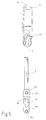
- Fig. 1 shows a row system from two structurally identical Vertical awnings 1.
- each vertical awning 1 include wall bracket 2, an awning box in the shape of a Sleeve 3, an awning track 4, two vertically running Guide rails 5 and two rail holders 6 and 7.
- Between the two wall brackets 2 of each vertical awning one winding shaft rotatably supported by the Covered sleeve 3 and therefore not in the drawing is recognizable.
- the winding shaft can be driven in by drive means Rotations.
- the edge of the awning is on the winding shaft 5 attached, the other edge of a fall rail 8th is appropriate.
- the drop rail 8 has two ends tubular or eyelet end pieces 9 provided on the both belonging to the relevant vertical awning 1 slide cylindrical guide rails.
- the guide rails 1 extend through the bores of the end pieces 9 through it.
- Each wall bracket 2 is made from a base part 11 and a bearing bracket 12.
- the base part has an elongated cuboid shape and is made of two flat sides 13 and 14 and two narrow sides 15 and 16 limited to the top and bottom End by a curved arcuate surface 17 and 18 respectively merge.
- the two flat sides 13 and 14 are parallel to each other, as well as this for the two narrow sides 15 and 16 applies.
- In the base part 11 are two to each other parallel and spaced straight T-slots 19 and 21 included, parallel to the narrow sides 15 and 16 run.
- the T-grooves 19 and 21 are on their upper End closed at 22 and 23, respectively, while at their bottom End insertion openings 24 and 25 contain the lower one Enforce page 17.
- the T-grooves 19 and 21 point each have a slot slot penetrating the front flat side 13 26 and 27 on.
- the T-groove 19 a countersunk through-hole in its groove bottom 28 29.
- the Groove slot 26 In the area of the through bore 29, the Groove slot 26 to the outside diameter of the countersink the through hole 29.
- the T-groove 21 is similarly in its groove bottom 33 with countersunk holes 34 and 35 and a recess 36 provided.
- the countersunk holes 34 and 35 are at the same height as the holes 29 and 31 and have the same dimensions as these. Analogous the same applies to recess 25.
- slot slot 27 widens in the area the countersunk holes 34 and 35.
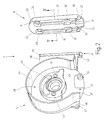
- the bearing bracket 12 is essentially plate-shaped Formation that is reflected in the top view a circular section 37 and a rectangular one Section 38 composed.
- the circular section 27 of the bearing bracket can easily be cambered to the outside, in one by the viewer 2 direction pointing away.
- the rectangular section 38 has a thickness that corresponds approximately to the width of the slot 26 and 27 and on its free narrow or front side is a rib or molding 39 formed.
- the rib 39 is a straight rib and together with the section 38 forms one in the Top view T-shaped cross section, which to the Cross section of the T-groove 19 or 21 is complementary.
- the rib 39 goes into a thickened extension 41 over which a threaded bore 42 for receiving a Includes locking screw.
- the axis of the threaded bore 42 stands vertically on the rib. Aligned when assembled the axis of the threaded bore 42 with the center of the circular or conical recess 34 or 36.
- the collar 44 has, apart from the opening 45 and the structures in the immediate vicinity of the opening 45 a tubular cylindrical shape. Concentric to this sits on the flat side 43 a one-piece molded Bearing seat 48 with a bearing seat bore contained therein 49.Both sides of the bearing seat bore 49 there are mounting threaded holes 51 for receiving of threaded screws that have a safety cover, not shown for a bearing located in the seat 49 secure axially.
- the bearing seat bore 49 is a blind bore, which ends on the flat side 45.
- an approximately semi-cylindrical extension 52 is formed, the in the same direction as the collar 44.
- the extension 52 which can best be seen in FIG. 3 a cylindrical bore 43 which serves as a receiving bore for the upper end of the relevant guide rail 5 is used. If necessary, the extension 52 can also be used Pass threaded bore 54 through which the inclusion of a Clamping screw for clamping the guide rail 5 in the Hole 53 is used.
- the assembly of the described vertical awning 1 is as follows:
- the winding shaft equipped with the awning cloth 4 is fixed at the ends with their bearings in two bearing brackets 12, in such a way that the two bearing brackets 12 with the Collar 44 to show each other. Between the two bearing brackets is on the collars 44 the recognizable in Fig. 1 Sleeve 3, which serves as an awning box and in the area of Opening 45 of the bearing bracket 12 has a continuous slot contains.
- This sleeve can be a section of a light metal or Plastic extrusion.
- the base parts 11 are mounted on the wall in such a way that the insertion openings 24 and 25 of the T-grooves 19 and 21 point down.
- the grooves 19, 21 run vertically and therefore perpendicular to the axis of the winding shaft.
- Fig. 5 shows a schematic perspective Representation of the left end of a vertical awning 1 which is not followed by another awning on the left. Out For reasons of clarity, the sleeve 3 is not shown and there is also no reproduction of the winding shaft or the awning track.
- the left bearing bracket is inserted 12 in the outer of the two T-grooves 19 and 21, so that the base part 11 essentially through the collar 44 or the sleeve 3 placed thereon is hidden.
- the other Groove of the base part 11 lies towards the center of the awning is free.
- the Rail holder 6 consists of a flange plate 61, which protrudes an integrally molded arm 62, which in a fist or thickening 63 ends.
- the thickening 63 contains a through or blind bore 64 for receiving of the lower end of the guide rail concerned 5.
- Crosswise a threaded bore 65 may be provided for this bore be into which a clamping screw can be screwed.
- the flange plate 61 contains two through holes 66 for fastening the flange plate 61 to the wall of the concerned building.
- both grooves 19 and 21 are equipped, which is why their distance from each other is such that after the insertion of the bearing bracket 12 not with each other collide.
- Fig. 6 shows again a flange plate 61, but two Arms 62a and 62b protrude.
- Each of the arms 62a, 62b carries at its free end one with the hole in question 64 provided clamping fist 63a or 63b.
- the distance between the mounting holes 64 for the two guide rails 5 corresponds to the distance between the receiving bores 53 of the two inserted in a common base part 11 Bearing bracket 12.
- the arrangement and configuration of the Wall bracket 2 is not for use with vertical awnings limited. It can also be used in marquee isolets be in which on or in the guide rails 5 Run sledges with drop arms on which the drop rail 8 is attached.
- the invention has been given by way of example only explained on a vertical awning, because this, apart of the components according to the invention, simpler is designed as a marquise with sledge and drop arms.
- each wall bracket consists of a base part that is attached to the Wall of the building is to be fastened and a bearing bracket for storing the winding shaft.
- the base part contains two Grooves and there can be one or two bearing brackets in the base part can be introduced.
- a bearing bracket in each groove sits so that two bearing brackets share a base part.
Landscapes
- Engineering & Computer Science (AREA)
- Architecture (AREA)
- Civil Engineering (AREA)
- Structural Engineering (AREA)
- Building Awnings And Sunshades (AREA)
- Tents Or Canopies (AREA)
- Blinds (AREA)
- Curtains And Furnishings For Windows Or Doors (AREA)
Applications Claiming Priority (2)
| Application Number | Priority Date | Filing Date | Title |
|---|---|---|---|
| DE29820914U | 1998-11-23 | ||
| DE29820914U DE29820914U1 (de) | 1998-11-23 | 1998-11-23 | Senkrechtmarkise |
Publications (3)
| Publication Number | Publication Date |
|---|---|
| EP1004743A2 true EP1004743A2 (fr) | 2000-05-31 |
| EP1004743A3 EP1004743A3 (fr) | 2002-01-09 |
| EP1004743B1 EP1004743B1 (fr) | 2005-07-06 |
Family
ID=8065708
Family Applications (1)
| Application Number | Title | Priority Date | Filing Date |
|---|---|---|---|
| EP99121274A Expired - Lifetime EP1004743B1 (fr) | 1998-11-23 | 1999-10-25 | Store vertical |
Country Status (3)
| Country | Link |
|---|---|
| EP (1) | EP1004743B1 (fr) |
| AT (1) | ATE299225T1 (fr) |
| DE (2) | DE29820914U1 (fr) |
Cited By (5)
| Publication number | Priority date | Publication date | Assignee | Title |
|---|---|---|---|---|
| FR2821969A1 (fr) * | 2001-03-06 | 2002-09-13 | Mobil Affiche Internat | Dispositif d'affichage selectif d'affiches |
| WO2009003538A1 (fr) * | 2007-07-03 | 2009-01-08 | Suncover S.P.A. | Joint articulé pour monter des cadres de stores sur des façades cintrées |
| EP2221429A3 (fr) * | 2009-02-03 | 2013-09-04 | Resstende S.r.l. | Construction de rideau déroulable pour masquer des surfaces vitrées |
| GB2583553A (en) * | 2019-11-26 | 2020-11-04 | Yewdale Investments Ltd | Window blind bracket cover |
| CN113066400A (zh) * | 2021-03-29 | 2021-07-02 | 江苏金牛星电子科技有限公司 | 一种滚动频率可调节的户外灯箱用滚动系统 |
Families Citing this family (2)
| Publication number | Priority date | Publication date | Assignee | Title |
|---|---|---|---|---|
| JP7154142B2 (ja) * | 2019-01-17 | 2022-10-17 | 株式会社Lixil | ブラインド装置 |
| JP7154140B2 (ja) * | 2019-01-17 | 2022-10-17 | 株式会社Lixil | ブラインド装置 |
Family Cites Families (2)
| Publication number | Priority date | Publication date | Assignee | Title |
|---|---|---|---|---|
| US1018110A (en) * | 1910-12-27 | 1912-02-20 | Joseph B Hogle | Window-shade fixture. |
| DE2728121A1 (de) * | 1977-06-22 | 1979-01-11 | Ade Werk Gmbh | Markise |
-
1998
- 1998-11-23 DE DE29820914U patent/DE29820914U1/de not_active Expired - Lifetime
-
1999
- 1999-10-25 DE DE59912237T patent/DE59912237D1/de not_active Expired - Fee Related
- 1999-10-25 AT AT99121274T patent/ATE299225T1/de not_active IP Right Cessation
- 1999-10-25 EP EP99121274A patent/EP1004743B1/fr not_active Expired - Lifetime
Cited By (7)
| Publication number | Priority date | Publication date | Assignee | Title |
|---|---|---|---|---|
| FR2821969A1 (fr) * | 2001-03-06 | 2002-09-13 | Mobil Affiche Internat | Dispositif d'affichage selectif d'affiches |
| WO2002071375A3 (fr) * | 2001-03-06 | 2003-02-20 | Mobil Affiche Internat | Dispositif d'affichage selectif d'affiches |
| WO2009003538A1 (fr) * | 2007-07-03 | 2009-01-08 | Suncover S.P.A. | Joint articulé pour monter des cadres de stores sur des façades cintrées |
| EP2221429A3 (fr) * | 2009-02-03 | 2013-09-04 | Resstende S.r.l. | Construction de rideau déroulable pour masquer des surfaces vitrées |
| GB2583553A (en) * | 2019-11-26 | 2020-11-04 | Yewdale Investments Ltd | Window blind bracket cover |
| GB2583553B (en) * | 2019-11-26 | 2021-06-23 | Yewdale Investments Ltd | Window blind bracket cover |
| CN113066400A (zh) * | 2021-03-29 | 2021-07-02 | 江苏金牛星电子科技有限公司 | 一种滚动频率可调节的户外灯箱用滚动系统 |
Also Published As
| Publication number | Publication date |
|---|---|
| EP1004743A3 (fr) | 2002-01-09 |
| EP1004743B1 (fr) | 2005-07-06 |
| DE59912237D1 (de) | 2005-08-11 |
| ATE299225T1 (de) | 2005-07-15 |
| DE29820914U1 (de) | 1999-01-28 |
Similar Documents
| Publication | Publication Date | Title |
|---|---|---|
| DE102012017948B3 (de) | Verfahren und Anordnung zum Befestigen eines Pfostens an einer Rahmenleiste eines Fensters oder einer Türe mittels eines Pfostenverbinders | |
| DE102006016045B4 (de) | Vorrichtung zur lösbaren Halterung von einem Flächenelement und deren Verwendung | |
| EP3705676B1 (fr) | Procédé de montage d'un coffre de volet roulant et coffre de volet roulant posé sur une partie du cadre | |
| EP1004743A2 (fr) | Store vertical | |
| DE3004313A1 (de) | Topfscharnier | |
| DE2504476A1 (de) | Beschlag fuer die befestigung eines profiltraegers zur bildung eines rahmens | |
| DE6942006U (de) | Anordnung von eckbeschlagteilen, insbesondere von kettenwinkeln, in profilrahmen von fenstern, tueren od.dgl. | |
| DE29907856U1 (de) | Führungsvorrichtung zur Aufnahme von Gleit- und Schiebeelementen an Möbeln | |
| DE3850762T3 (de) | Optischer Massstab. | |
| EP0122368A2 (fr) | Raccord à vis avec fixation de tête de vis et procédé de fixation des pièces à distance ajustable | |
| EP2628426B1 (fr) | Support pour serviette anti-rotation | |
| DE4421690A1 (de) | Variables Warenpräsentations- und Aufnahmesystem | |
| DE2923903A1 (de) | Wandbefestigungselement fuer plattenheizkoerper | |
| DE69410982T2 (de) | Stellbare Vorrichtung, insbesondere für Metallrahmen | |
| EP0040180A1 (fr) | Tréteau de montage | |
| DE2821101C3 (de) | Auszugführung für in einem Gestell gehaltene Schubladen o.dgl | |
| DE10211709C1 (de) | Duschkabine mit einer wenigstens eine Glasplatte aufweisenden Duschtrennwand | |
| DE3328232C2 (de) | Raumfachwerk | |
| DE3232766C1 (de) | Aus Profilteilen bestehendes Gestell | |
| EP1033093A1 (fr) | Console pour la fixation de paniers, bassins ou plateaux entre les côtés de cadres pour des tiroirs en vertical | |
| DE102006016022B4 (de) | Vorrichtung zur drehbaren Halterung von zwei Flächenelementen und deren Verwendung | |
| DE3711679A1 (de) | Halterung fuer badezimmerarmaturen und -accessoires | |
| DE2236397A1 (de) | Einstellbarer aufhaengebeschlag fuer wandschraenke | |
| EP0272375A2 (fr) | Store | |
| DE7027172U (de) | Befestigungsbeschlag fuer moebel, insbesondere haengemoebel. |
Legal Events
| Date | Code | Title | Description |
|---|---|---|---|
| PUAI | Public reference made under article 153(3) epc to a published international application that has entered the european phase |
Free format text: ORIGINAL CODE: 0009012 |
|
| AK | Designated contracting states |
Kind code of ref document: A2 Designated state(s): AT BE CH CY DE DK ES FI FR GB GR IE IT LI LU MC NL PT SE Kind code of ref document: A2 Designated state(s): AT CH DE FR IT LI |
|
| AX | Request for extension of the european patent |
Free format text: AL;LT;LV;MK;RO;SI |
|
| PUAL | Search report despatched |
Free format text: ORIGINAL CODE: 0009013 |
|
| AK | Designated contracting states |
Kind code of ref document: A3 Designated state(s): AT BE CH CY DE DK ES FI FR GB GR IE IT LI LU MC NL PT SE |
|
| AX | Request for extension of the european patent |
Free format text: AL;LT;LV;MK;RO;SI |
|
| RIC1 | Information provided on ipc code assigned before grant |
Free format text: 7E 06B 9/40 A, 7E 06B 9/58 B, 7E 04F 10/06 B |
|
| 17P | Request for examination filed |
Effective date: 20020403 |
|
| 17Q | First examination report despatched |
Effective date: 20020809 |
|
| AKX | Designation fees paid |
Free format text: AT CH DE FR IT LI |
|
| GRAP | Despatch of communication of intention to grant a patent |
Free format text: ORIGINAL CODE: EPIDOSNIGR1 |
|
| GRAJ | Information related to disapproval of communication of intention to grant by the applicant or resumption of examination proceedings by the epo deleted |
Free format text: ORIGINAL CODE: EPIDOSDIGR1 |
|
| GRAP | Despatch of communication of intention to grant a patent |
Free format text: ORIGINAL CODE: EPIDOSNIGR1 |
|
| GRAS | Grant fee paid |
Free format text: ORIGINAL CODE: EPIDOSNIGR3 |
|
| GRAA | (expected) grant |
Free format text: ORIGINAL CODE: 0009210 |
|
| AK | Designated contracting states |
Kind code of ref document: B1 Designated state(s): AT CH DE FR IT LI |
|
| PG25 | Lapsed in a contracting state [announced via postgrant information from national office to epo] |
Ref country code: IT Free format text: LAPSE BECAUSE OF FAILURE TO SUBMIT A TRANSLATION OF THE DESCRIPTION OR TO PAY THE FEE WITHIN THE PRESCRIBED TIME-LIMIT;WARNING: LAPSES OF ITALIAN PATENTS WITH EFFECTIVE DATE BEFORE 2007 MAY HAVE OCCURRED AT ANY TIME BEFORE 2007. THE CORRECT EFFECTIVE DATE MAY BE DIFFERENT FROM THE ONE RECORDED. Effective date: 20050706 |
|
| REG | Reference to a national code |
Ref country code: CH Ref legal event code: EP |
|
| REF | Corresponds to: |
Ref document number: 59912237 Country of ref document: DE Date of ref document: 20050811 Kind code of ref document: P |
|
| PG25 | Lapsed in a contracting state [announced via postgrant information from national office to epo] |
Ref country code: LI Free format text: LAPSE BECAUSE OF NON-PAYMENT OF DUE FEES Effective date: 20051031 Ref country code: CH Free format text: LAPSE BECAUSE OF NON-PAYMENT OF DUE FEES Effective date: 20051031 |
|
| PLBE | No opposition filed within time limit |
Free format text: ORIGINAL CODE: 0009261 |
|
| STAA | Information on the status of an ep patent application or granted ep patent |
Free format text: STATUS: NO OPPOSITION FILED WITHIN TIME LIMIT |
|
| 26N | No opposition filed |
Effective date: 20060407 |
|
| REG | Reference to a national code |
Ref country code: CH Ref legal event code: PL |
|
| EN | Fr: translation not filed | ||
| PG25 | Lapsed in a contracting state [announced via postgrant information from national office to epo] |
Ref country code: FR Free format text: LAPSE BECAUSE OF FAILURE TO SUBMIT A TRANSLATION OF THE DESCRIPTION OR TO PAY THE FEE WITHIN THE PRESCRIBED TIME-LIMIT Effective date: 20060901 |
|
| PGFP | Annual fee paid to national office [announced via postgrant information from national office to epo] |
Ref country code: AT Payment date: 20061020 Year of fee payment: 8 |
|
| PGFP | Annual fee paid to national office [announced via postgrant information from national office to epo] |
Ref country code: DE Payment date: 20061031 Year of fee payment: 8 |
|
| PG25 | Lapsed in a contracting state [announced via postgrant information from national office to epo] |
Ref country code: DE Free format text: LAPSE BECAUSE OF NON-PAYMENT OF DUE FEES Effective date: 20080501 |
|
| PG25 | Lapsed in a contracting state [announced via postgrant information from national office to epo] |
Ref country code: AT Free format text: LAPSE BECAUSE OF NON-PAYMENT OF DUE FEES Effective date: 20071025 Ref country code: FR Free format text: LAPSE BECAUSE OF FAILURE TO SUBMIT A TRANSLATION OF THE DESCRIPTION OR TO PAY THE FEE WITHIN THE PRESCRIBED TIME-LIMIT Effective date: 20051031 |
|
| PG25 | Lapsed in a contracting state [announced via postgrant information from national office to epo] |
Ref country code: FR Free format text: LAPSE BECAUSE OF FAILURE TO SUBMIT A TRANSLATION OF THE DESCRIPTION OR TO PAY THE FEE WITHIN THE PRESCRIBED TIME-LIMIT Effective date: 20050706 |