EP1004810A2 - Verbindungsstücke für doppelwandige Rohre und Druckformen für die Herstellung derselben - Google Patents
Verbindungsstücke für doppelwandige Rohre und Druckformen für die Herstellung derselben Download PDFInfo
- Publication number
- EP1004810A2 EP1004810A2 EP99203852A EP99203852A EP1004810A2 EP 1004810 A2 EP1004810 A2 EP 1004810A2 EP 99203852 A EP99203852 A EP 99203852A EP 99203852 A EP99203852 A EP 99203852A EP 1004810 A2 EP1004810 A2 EP 1004810A2
- Authority
- EP
- European Patent Office
- Prior art keywords
- union
- tube
- wall
- seat
- duct
- Prior art date
- Legal status (The legal status is an assumption and is not a legal conclusion. Google has not performed a legal analysis and makes no representation as to the accuracy of the status listed.)
- Granted
Links
- 238000004519 manufacturing process Methods 0.000 title claims description 10
- 230000004927 fusion Effects 0.000 claims description 2
- 238000003825 pressing Methods 0.000 claims description 2
- 239000000463 material Substances 0.000 description 9
- 239000007788 liquid Substances 0.000 description 3
- 238000010276 construction Methods 0.000 description 2
- 239000012530 fluid Substances 0.000 description 2
- 238000000034 method Methods 0.000 description 2
- 238000004026 adhesive bonding Methods 0.000 description 1
- 238000009530 blood pressure measurement Methods 0.000 description 1
- 239000003638 chemical reducing agent Substances 0.000 description 1
- 230000008878 coupling Effects 0.000 description 1
- 238000010168 coupling process Methods 0.000 description 1
- 238000005859 coupling reaction Methods 0.000 description 1
- 229920001971 elastomer Polymers 0.000 description 1
- 239000000806 elastomer Substances 0.000 description 1
- 239000003292 glue Substances 0.000 description 1
- 238000010438 heat treatment Methods 0.000 description 1
- 238000002844 melting Methods 0.000 description 1
- 230000008018 melting Effects 0.000 description 1
- 239000000203 mixture Substances 0.000 description 1
Images


Classifications
-
- B—PERFORMING OPERATIONS; TRANSPORTING
- B29—WORKING OF PLASTICS; WORKING OF SUBSTANCES IN A PLASTIC STATE IN GENERAL
- B29C—SHAPING OR JOINING OF PLASTICS; SHAPING OF MATERIAL IN A PLASTIC STATE, NOT OTHERWISE PROVIDED FOR; AFTER-TREATMENT OF THE SHAPED PRODUCTS, e.g. REPAIRING
- B29C65/00—Joining or sealing of preformed parts, e.g. welding of plastics materials; Apparatus therefor
- B29C65/02—Joining or sealing of preformed parts, e.g. welding of plastics materials; Apparatus therefor by heating, with or without pressure
- B29C65/34—Joining or sealing of preformed parts, e.g. welding of plastics materials; Apparatus therefor by heating, with or without pressure using heated elements which remain in the joint, e.g. "verlorenes Schweisselement"
- B29C65/3404—Joining or sealing of preformed parts, e.g. welding of plastics materials; Apparatus therefor by heating, with or without pressure using heated elements which remain in the joint, e.g. "verlorenes Schweisselement" characterised by the type of heated elements which remain in the joint
- B29C65/342—Joining or sealing of preformed parts, e.g. welding of plastics materials; Apparatus therefor by heating, with or without pressure using heated elements which remain in the joint, e.g. "verlorenes Schweisselement" characterised by the type of heated elements which remain in the joint comprising at least a single wire, e.g. in the form of a winding
-
- B—PERFORMING OPERATIONS; TRANSPORTING
- B29—WORKING OF PLASTICS; WORKING OF SUBSTANCES IN A PLASTIC STATE IN GENERAL
- B29C—SHAPING OR JOINING OF PLASTICS; SHAPING OF MATERIAL IN A PLASTIC STATE, NOT OTHERWISE PROVIDED FOR; AFTER-TREATMENT OF THE SHAPED PRODUCTS, e.g. REPAIRING
- B29C66/00—General aspects of processes or apparatus for joining preformed parts
- B29C66/01—General aspects dealing with the joint area or with the area to be joined
- B29C66/05—Particular design of joint configurations
- B29C66/10—Particular design of joint configurations particular design of the joint cross-sections
- B29C66/11—Joint cross-sections comprising a single joint-segment, i.e. one of the parts to be joined comprising a single joint-segment in the joint cross-section
- B29C66/112—Single lapped joints
- B29C66/1122—Single lap to lap joints, i.e. overlap joints
-
- B—PERFORMING OPERATIONS; TRANSPORTING
- B29—WORKING OF PLASTICS; WORKING OF SUBSTANCES IN A PLASTIC STATE IN GENERAL
- B29C—SHAPING OR JOINING OF PLASTICS; SHAPING OF MATERIAL IN A PLASTIC STATE, NOT OTHERWISE PROVIDED FOR; AFTER-TREATMENT OF THE SHAPED PRODUCTS, e.g. REPAIRING
- B29C66/00—General aspects of processes or apparatus for joining preformed parts
- B29C66/01—General aspects dealing with the joint area or with the area to be joined
- B29C66/05—Particular design of joint configurations
- B29C66/10—Particular design of joint configurations particular design of the joint cross-sections
- B29C66/12—Joint cross-sections combining only two joint-segments; Tongue and groove joints; Tenon and mortise joints; Stepped joint cross-sections
- B29C66/128—Stepped joint cross-sections
- B29C66/1282—Stepped joint cross-sections comprising at least one overlap joint-segment
- B29C66/12821—Stepped joint cross-sections comprising at least one overlap joint-segment comprising at least two overlap joint-segments
-
- B—PERFORMING OPERATIONS; TRANSPORTING
- B29—WORKING OF PLASTICS; WORKING OF SUBSTANCES IN A PLASTIC STATE IN GENERAL
- B29C—SHAPING OR JOINING OF PLASTICS; SHAPING OF MATERIAL IN A PLASTIC STATE, NOT OTHERWISE PROVIDED FOR; AFTER-TREATMENT OF THE SHAPED PRODUCTS, e.g. REPAIRING
- B29C66/00—General aspects of processes or apparatus for joining preformed parts
- B29C66/01—General aspects dealing with the joint area or with the area to be joined
- B29C66/05—Particular design of joint configurations
- B29C66/10—Particular design of joint configurations particular design of the joint cross-sections
- B29C66/12—Joint cross-sections combining only two joint-segments; Tongue and groove joints; Tenon and mortise joints; Stepped joint cross-sections
- B29C66/128—Stepped joint cross-sections
- B29C66/1284—Stepped joint cross-sections comprising at least one butt joint-segment
- B29C66/12841—Stepped joint cross-sections comprising at least one butt joint-segment comprising at least two butt joint-segments
-
- B—PERFORMING OPERATIONS; TRANSPORTING
- B29—WORKING OF PLASTICS; WORKING OF SUBSTANCES IN A PLASTIC STATE IN GENERAL
- B29C—SHAPING OR JOINING OF PLASTICS; SHAPING OF MATERIAL IN A PLASTIC STATE, NOT OTHERWISE PROVIDED FOR; AFTER-TREATMENT OF THE SHAPED PRODUCTS, e.g. REPAIRING
- B29C66/00—General aspects of processes or apparatus for joining preformed parts
- B29C66/50—General aspects of joining tubular articles; General aspects of joining long products, i.e. bars or profiled elements; General aspects of joining single elements to tubular articles, hollow articles or bars; General aspects of joining several hollow-preforms to form hollow or tubular articles
- B29C66/51—Joining tubular articles, profiled elements or bars; Joining single elements to tubular articles, hollow articles or bars; Joining several hollow-preforms to form hollow or tubular articles
- B29C66/52—Joining tubular articles, bars or profiled elements
- B29C66/522—Joining tubular articles
- B29C66/5221—Joining tubular articles for forming coaxial connections, i.e. the tubular articles to be joined forming a zero angle relative to each other
-
- B—PERFORMING OPERATIONS; TRANSPORTING
- B29—WORKING OF PLASTICS; WORKING OF SUBSTANCES IN A PLASTIC STATE IN GENERAL
- B29C—SHAPING OR JOINING OF PLASTICS; SHAPING OF MATERIAL IN A PLASTIC STATE, NOT OTHERWISE PROVIDED FOR; AFTER-TREATMENT OF THE SHAPED PRODUCTS, e.g. REPAIRING
- B29C66/00—General aspects of processes or apparatus for joining preformed parts
- B29C66/50—General aspects of joining tubular articles; General aspects of joining long products, i.e. bars or profiled elements; General aspects of joining single elements to tubular articles, hollow articles or bars; General aspects of joining several hollow-preforms to form hollow or tubular articles
- B29C66/51—Joining tubular articles, profiled elements or bars; Joining single elements to tubular articles, hollow articles or bars; Joining several hollow-preforms to form hollow or tubular articles
- B29C66/52—Joining tubular articles, bars or profiled elements
- B29C66/522—Joining tubular articles
- B29C66/5223—Joining tubular articles for forming corner connections or elbows, e.g. for making V-shaped pieces
- B29C66/52231—Joining tubular articles for forming corner connections or elbows, e.g. for making V-shaped pieces with a right angle, e.g. for making L-shaped pieces
-
- B—PERFORMING OPERATIONS; TRANSPORTING
- B29—WORKING OF PLASTICS; WORKING OF SUBSTANCES IN A PLASTIC STATE IN GENERAL
- B29C—SHAPING OR JOINING OF PLASTICS; SHAPING OF MATERIAL IN A PLASTIC STATE, NOT OTHERWISE PROVIDED FOR; AFTER-TREATMENT OF THE SHAPED PRODUCTS, e.g. REPAIRING
- B29C66/00—General aspects of processes or apparatus for joining preformed parts
- B29C66/50—General aspects of joining tubular articles; General aspects of joining long products, i.e. bars or profiled elements; General aspects of joining single elements to tubular articles, hollow articles or bars; General aspects of joining several hollow-preforms to form hollow or tubular articles
- B29C66/51—Joining tubular articles, profiled elements or bars; Joining single elements to tubular articles, hollow articles or bars; Joining several hollow-preforms to form hollow or tubular articles
- B29C66/52—Joining tubular articles, bars or profiled elements
- B29C66/522—Joining tubular articles
- B29C66/5224—Joining tubular articles for forming fork-shaped connections, e.g. for making Y-shaped pieces
- B29C66/52241—Joining tubular articles for forming fork-shaped connections, e.g. for making Y-shaped pieces with two right angles, e.g. for making T-shaped pieces
-
- B—PERFORMING OPERATIONS; TRANSPORTING
- B29—WORKING OF PLASTICS; WORKING OF SUBSTANCES IN A PLASTIC STATE IN GENERAL
- B29C—SHAPING OR JOINING OF PLASTICS; SHAPING OF MATERIAL IN A PLASTIC STATE, NOT OTHERWISE PROVIDED FOR; AFTER-TREATMENT OF THE SHAPED PRODUCTS, e.g. REPAIRING
- B29C66/00—General aspects of processes or apparatus for joining preformed parts
- B29C66/50—General aspects of joining tubular articles; General aspects of joining long products, i.e. bars or profiled elements; General aspects of joining single elements to tubular articles, hollow articles or bars; General aspects of joining several hollow-preforms to form hollow or tubular articles
- B29C66/51—Joining tubular articles, profiled elements or bars; Joining single elements to tubular articles, hollow articles or bars; Joining several hollow-preforms to form hollow or tubular articles
- B29C66/52—Joining tubular articles, bars or profiled elements
- B29C66/522—Joining tubular articles
- B29C66/5229—Joining tubular articles involving the use of a socket
- B29C66/52291—Joining tubular articles involving the use of a socket said socket comprising a stop
- B29C66/52292—Joining tubular articles involving the use of a socket said socket comprising a stop said stop being internal
-
- B—PERFORMING OPERATIONS; TRANSPORTING
- B29—WORKING OF PLASTICS; WORKING OF SUBSTANCES IN A PLASTIC STATE IN GENERAL
- B29C—SHAPING OR JOINING OF PLASTICS; SHAPING OF MATERIAL IN A PLASTIC STATE, NOT OTHERWISE PROVIDED FOR; AFTER-TREATMENT OF THE SHAPED PRODUCTS, e.g. REPAIRING
- B29C66/00—General aspects of processes or apparatus for joining preformed parts
- B29C66/70—General aspects of processes or apparatus for joining preformed parts characterised by the composition, physical properties or the structure of the material of the parts to be joined; Joining with non-plastics material
- B29C66/72—General aspects of processes or apparatus for joining preformed parts characterised by the composition, physical properties or the structure of the material of the parts to be joined; Joining with non-plastics material characterised by the structure of the material of the parts to be joined
- B29C66/723—General aspects of processes or apparatus for joining preformed parts characterised by the composition, physical properties or the structure of the material of the parts to be joined; Joining with non-plastics material characterised by the structure of the material of the parts to be joined being multi-layered
-
- B—PERFORMING OPERATIONS; TRANSPORTING
- B29—WORKING OF PLASTICS; WORKING OF SUBSTANCES IN A PLASTIC STATE IN GENERAL
- B29C—SHAPING OR JOINING OF PLASTICS; SHAPING OF MATERIAL IN A PLASTIC STATE, NOT OTHERWISE PROVIDED FOR; AFTER-TREATMENT OF THE SHAPED PRODUCTS, e.g. REPAIRING
- B29C66/00—General aspects of processes or apparatus for joining preformed parts
- B29C66/70—General aspects of processes or apparatus for joining preformed parts characterised by the composition, physical properties or the structure of the material of the parts to be joined; Joining with non-plastics material
- B29C66/72—General aspects of processes or apparatus for joining preformed parts characterised by the composition, physical properties or the structure of the material of the parts to be joined; Joining with non-plastics material characterised by the structure of the material of the parts to be joined
- B29C66/725—General aspects of processes or apparatus for joining preformed parts characterised by the composition, physical properties or the structure of the material of the parts to be joined; Joining with non-plastics material characterised by the structure of the material of the parts to be joined being hollow-walled or honeycombs
- B29C66/7252—General aspects of processes or apparatus for joining preformed parts characterised by the composition, physical properties or the structure of the material of the parts to be joined; Joining with non-plastics material characterised by the structure of the material of the parts to be joined being hollow-walled or honeycombs hollow-walled
- B29C66/72523—General aspects of processes or apparatus for joining preformed parts characterised by the composition, physical properties or the structure of the material of the parts to be joined; Joining with non-plastics material characterised by the structure of the material of the parts to be joined being hollow-walled or honeycombs hollow-walled multi-channelled or multi-tubular
-
- F—MECHANICAL ENGINEERING; LIGHTING; HEATING; WEAPONS; BLASTING
- F16—ENGINEERING ELEMENTS AND UNITS; GENERAL MEASURES FOR PRODUCING AND MAINTAINING EFFECTIVE FUNCTIONING OF MACHINES OR INSTALLATIONS; THERMAL INSULATION IN GENERAL
- F16L—PIPES; JOINTS OR FITTINGS FOR PIPES; SUPPORTS FOR PIPES, CABLES OR PROTECTIVE TUBING; MEANS FOR THERMAL INSULATION IN GENERAL
- F16L47/00—Connecting arrangements or other fittings specially adapted to be made of plastics or to be used with pipes made of plastics
- F16L47/02—Welded joints; Adhesive joints
- F16L47/03—Welded joints with an electrical resistance incorporated in the joint
Definitions
- the present invention relates to unions for tubes of the double wall type i.e. tubes in which the internal duct is surrounded by a chamber or jacket coaxial therewith.
- the present invention also relates to dies for making said unions.
- such tubes are used for conveyance of polluting liquids while holding the external jacket under pressure and passing the liquid through the central duct. If the tube is punctured the resulting pressure drop in the external jacket is detected and supply of the conveyed liquid can be promptly stopped.
- the sleeve is fitted on the tube at the terminal end of the external tube wall so that the double-wall tube will enter the sleeve from the end with larger diameter but only the internal core of the tube emerges from the reduced diameter end.
- the ends of the sleeve are clamped on the tube so that the terminal edge of the tube external wall is sealed inside the sleeve in a zone where the sleeve has the tube connection. In this manner the sleeve seals the air space in the double-wall tube and connects it to the tube grafted to the connection on the outside of the sleeve.
- this sleeve can serve to terminate the external wall of the tube so as to reduce the double-wall tube to a single-wall tube consisting of the internal wall of the double-wall tube.
- Two double-wall tube sections can be connected by using two sleeves of the above mentioned type to reduce to a single-wall tube the tube ends to be connected and then jointing the single-wall tubes thus obtained with a normal known tube union.
- the air spaces terminated in the sleeves are connected together by means of a short length of tube with both ends grafted to the sleeve connections.
- the general purpose of the present invention is to overcome the drawbacks of the prior art by supplying unions easy, safe and fast to use for double-wall tubes. Another purpose is to supply dies therefor.
- a tube union having a first external wall and a second internal wall coaxial with the first to define a chamber around a central duct with the union comprising at least two seats for reception each of one end of a tube to be connected and each seat comprising a first surface designed to adhere to an end segment of the first wall of a tube inserted in the seat and a second surface coaxial with the first and designed to adhere to an end segment of the second wall of said tube with there being between the first and second surfaces of each seat of the union a connection surface with the union comprising at least one first duct leading onto said connection surfaces to provide connection between the chambers of tubes inserted in the seats and at least one second duct leading into spaces circumscribed by the second surfaces to provide connection between the central ducts of said tubes.
- a die for production of unions for double-wall tubes with air space comprising plugs for making seats to receive the ends of the tubes to be jointed and broaches for making ducts for connection of the air space of the tubes when the die is in pressing position with the broaches intersecting the plugs and entering them through the mouthpieces of said seats.
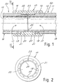
- FIGS. 1 shows a first union indicated as a whole by reference number 10, in the form of a sleeve.
- the unions in accordance with the present invention are designed to be employed for permanent connection of double-wall tubes 50 i.e. the type having a first external wall 11 and a second internal wall 12 coaxial with the first to define a chamber 13 around a central duct 14. If necessary the tube can even be the multilayer type with the innermost layer 15 suited for contact with the fluid conveyed and external layers suited for jointing with the union.
- the joint can be made by various methods designed for permanent connection such as electric furnace melting by means of heating resistances 16 embedded in the sleeve material, polyfusion or gluing with suitable glue.
- the sleeve will be produced with suitable material or compositions of members of suitable materials as may be readily imagined by those skilled in the art so that the selected joint system can also be used by virtue of the material or materials composing the tubes to be jointed so that the appropriate surfaces of the union can adhere permanently to the corresponding tube walls.
- FIG 1 The union of FIG 1 comprises two seats 17 for reception each of one end of a tube 18 to be connected.
- Each seat comprises a first surface 19 designed to adhere to an end segment of the first wall 11 of a tube inserted in the seat and a second surface 20 coaxial with the first and designed to adhere to an end segment of the second wall 12 of the tube.
- connection surface 21 which can advantageously constitute the head beat for at least the external wall 11 of the tube inserted in the seat.
- first and second surfaces are arranged sequentially in the seat with the connection surface defining a ledge between them to receive a tube with one end of the second wall 12 extending beyond the end of the first wall 11.
- the first wall adheres externally to the union surface 19 and the second wall adheres to the union surface 20 with its face turned into the space 13.
- the union comprises in its body first ducts 22 opening onto said connection surfaces 21 and second ducts 23 opening into spaces circumscribed by the second surfaces 20.
- first ducts 22 provide the connection between the chambers 13 of the tubes inserted in the seats while the second ducts 23 provide the connection between the central ducts of said tubes.
- the two seats can be arranged coaxially and in opposite directions.
- the central duct 23 can be reduced and the two seats can be virtually extensions of each other with only a possible separating circumferential ribbing 24 designed to define a head beat for the inner wall 12 of a tube inserted in the seat.
- first ducts 22 are a plurality and surround the second central duct 23 or main axial duct peripherally.
- a union in accordance with the present invention could be provided to form a joint member such as an elbow or a bend.
- a union 110 with seats 117 having coupling surfaces 119, 120 connected by a surface 121 with connecting ducts 122, and 123.
- FIG 4 shows a T union applying the principles of the present invention. Parts similar to those of FIG 1 are indicated by the same reference numbers increased by two hundred.
- T union 210 with seats 217 having connection surfaces 219, 220 for external wall and internal wall of double-wall tubes.
- the two connection surfaces of each seat are connected by means of an intermediate connecting surface 221.
- Passages or ducts 222, 223 connect the seats 217 to provide continuity respectively between the air spaces and between the internal ducts of the tubes jointed in the seats 217.
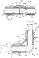
- FIG 5 shows a variant embodiment of a linear union in accordance with the present invention.
- the union (indicated as a whole by reference number 310) has opposite seats 317 having connection surfaces 319, 320 for external wall and internal wall of a pair of double-wall tubes to be jointed.
- the seats 317 are aligned and connected by the passage 323. Between the wall 319 and the wall 320 of each seat there is a connecting surface 321.
- the surface 321 is inclined to define an annular chamber 326 for connection with the air space of the tube in the seat.
- a duct 322 connects the seats near the connection surfaces to provide continuity between the air spaces of the tubes jointed in the seats 317.
- the duct 322 can be connected to a valve 325 which permits easy access to the air space of the jointed tubes for example for pressure measurement or addition of fluid to the air space or taking it therefrom.
- the duct 322 is divided in two semi-ducts 322a, 322b having their axis inclined with respect to the main axis of the union seats to meet in an intermediate zone in which to connect the valve 325.
- the union zone 310 in which passes the duct 322 is outside the main body of the union.
- FIG 6 shows a variant embodiment of a bend union provided in accordance with the present invention.
- the union (indicated as a whole by reference number 410) has seats 417 having connection surfaces 419, 420 for the external wall and internal wall of a pair of double-wall tubes to be jointed.
- the seats 417 are connected by the curved passage 423. Between the wall 419 and the wall 420 of each seat there is a connecting surface 421 inclined to define an annular chamber 426 for connection with the air space of the tube in the seat.
- a duct 422 connects the seats near the connection surfaces to provide continuity between the air spaces of the tubes jointed in the seats 417.
- the duct 422 arranged between the arms of the curve has a rectilinear axis 427 which is inclined with respect to the main axes of the seats 417 and its virtual extension emerges from the seats 417 through their tube introduction mouths.
- construction of the union is facilitated because the production die can have a broach running along the axis 427 which traverses the plugs 429 for production of the seats 417 and the duct 422.
- FIG 7 shows an embodiment of a T union in accordance with the present invention indicated by reference number 510.
- FIG also shows the plugs 529 and broaches 528 of a production die 530.
- the die with its ducts for feeding the plastic material and its various other accessories is shown only partially as the rest is readily imaginable to those skilled in the art on the basis of the drawings and description given here.
- the union 510 has seats 517 having connection surfaces 519, 520 for the external wall and internal wall of double-wall tubes to be jointed.
- the three seats 517 are connected by means of the passage to T 523.
- a pair of ducts 522 connect the seats near the connecting surfaces to provide continuity between the air spaces of the tubes jointed in the seats 517.
- the ducts 522 have a rectilinear axis 527 which is inclined with respect to the main axes of the seats 517 so that each duct intersects a pair of connecting surfaces 521.
- the union can be made up of an innermost part of material suited for connection with the tube material and an outer part of different material selected for example for its mechanical characteristics.
Landscapes
- Engineering & Computer Science (AREA)
- Mechanical Engineering (AREA)
- General Engineering & Computer Science (AREA)
- Quick-Acting Or Multi-Walled Pipe Joints (AREA)
- Panels For Use In Building Construction (AREA)
- External Artificial Organs (AREA)
- Branch Pipes, Bends, And The Like (AREA)
- Lining Or Joining Of Plastics Or The Like (AREA)
Applications Claiming Priority (2)
| Application Number | Priority Date | Filing Date | Title |
|---|---|---|---|
| ITMI980753U | 1998-11-23 | ||
| IT1998MI000753U IT244388Y1 (it) | 1998-11-23 | 1998-11-23 | Raccordi per tubi a doppia parete |
Publications (3)
| Publication Number | Publication Date |
|---|---|
| EP1004810A2 true EP1004810A2 (de) | 2000-05-31 |
| EP1004810A3 EP1004810A3 (de) | 2000-07-19 |
| EP1004810B1 EP1004810B1 (de) | 2003-02-26 |
Family
ID=11379712
Family Applications (1)
| Application Number | Title | Priority Date | Filing Date |
|---|---|---|---|
| EP99203852A Expired - Lifetime EP1004810B1 (de) | 1998-11-23 | 1999-11-18 | Verbindungsstücke für doppelwandige Rohre und Druckformen für die Herstellung derselben |
Country Status (5)
| Country | Link |
|---|---|
| US (1) | US6428054B1 (de) |
| EP (1) | EP1004810B1 (de) |
| AT (1) | ATE233388T1 (de) |
| DE (1) | DE69905541T2 (de) |
| IT (1) | IT244388Y1 (de) |
Cited By (4)
| Publication number | Priority date | Publication date | Assignee | Title |
|---|---|---|---|---|
| US6394502B1 (en) | 1998-03-11 | 2002-05-28 | Kungsors Plast Ab | Electrofusion coupler |
| KR100889476B1 (ko) | 2008-12-03 | 2009-03-19 | 폴리텍 주식회사 | 융착 성능이 향상된 융착식 연결부재 |
| WO2012115571A1 (en) * | 2011-02-25 | 2012-08-30 | Kungsörs Plast AB | Fusion welding socket |
| US10274120B2 (en) | 2009-03-26 | 2019-04-30 | Franklin Fueling Systems Limited | Couplings |
Families Citing this family (29)
| Publication number | Priority date | Publication date | Assignee | Title |
|---|---|---|---|---|
| AU780812B2 (en) * | 1999-09-14 | 2005-04-21 | Georg Fischer Wavin Ag | Improved welding socket |
| US6565127B2 (en) * | 2001-03-08 | 2003-05-20 | Environ Products, Inc. | Pipe coupling device and assembly |
| US6781099B2 (en) * | 2001-03-12 | 2004-08-24 | Karl-Heinz Krah Gmbh | Electrofusion socket forming system |
| ITMI20012257A1 (it) * | 2001-10-26 | 2003-04-26 | Nupi S P A | Tubo multistrato con estremita' saldabile testa a testa e metodo di saldatura di un tubo multistrato |
| US6848720B2 (en) * | 2002-08-09 | 2005-02-01 | The Boeing Company | Shrouded fluid-conducting apparatus |
| US7493911B2 (en) * | 2002-08-09 | 2009-02-24 | The Boeing Company | Shrouded valve apparatus and related methods |
| NZ560600A (en) * | 2005-02-25 | 2009-07-31 | Glynwed Pipe Systems Ltd | Method for joining multi-layered pipe |
| US7309047B2 (en) * | 2005-02-25 | 2007-12-18 | The Boeing Company | Systems and methods for controlling flexible communication links used for aircraft refueling |
| US7469863B1 (en) * | 2005-03-24 | 2008-12-30 | The Boeing Company | Systems and methods for automatically and semiautomatically controlling aircraft refueling |
| US7213787B2 (en) * | 2005-06-07 | 2007-05-08 | The Boeing Company | Valves for annular conduits including aircraft fuel conduits and associated systems and methods |
| US7637458B2 (en) * | 2005-06-08 | 2009-12-29 | The Boeing Company | Systems and methods for providing back-up hydraulic power for aircraft, including tanker aircraft |
| US7581700B2 (en) * | 2005-06-09 | 2009-09-01 | The Boeing Company | Adjustable fittings for attaching support members to fluid conduits, including aircraft fuel conduits, and associated systems and methods |
| US7293741B2 (en) * | 2005-06-09 | 2007-11-13 | The Boeing Company | System and methods for distributing loads from fluid conduits, including aircraft fuel conduits |
| US7533850B2 (en) | 2005-06-09 | 2009-05-19 | The Boeing Company | Fittings with redundant seals for aircraft fuel lines, fuel tanks, and other systems |
| US7437952B2 (en) * | 2005-06-10 | 2008-10-21 | The Boeing Company | Shrouded body flow meter assembly |
| US7458543B2 (en) * | 2005-06-10 | 2008-12-02 | The Boeing Company | Aerial refueling system |
| US7219857B2 (en) * | 2005-06-20 | 2007-05-22 | The Boeing Company | Controllable refueling drogues and associated systems and methods |
| US7472868B2 (en) * | 2005-09-01 | 2009-01-06 | The Boeing Company | Systems and methods for controlling an aerial refueling device |
| US20070102583A1 (en) * | 2005-10-26 | 2007-05-10 | Cutler Theron L | Systems and methods for reducing surge loads in hose assemblies, including aircraft refueling hose assemblies |
| CA2864762C (en) * | 2012-02-17 | 2019-06-04 | 8193053 Canada Ltd. | Pipe, pipe connection and pipeline system |
| FR2994593B1 (fr) * | 2012-08-20 | 2014-09-05 | Technip France | Raccord intermediaire de connexion d'elements de conduite rigide de transport de fluide, reseau de conduites et procede d'assemblage associes |
| JP6077348B2 (ja) * | 2013-03-19 | 2017-02-08 | リビングエンジニアリング株式会社 | 異径ホース継手 |
| US9719622B2 (en) | 2013-07-08 | 2017-08-01 | Georg Fischer Harvel Llc | Electrofusion fittings and methods |
| US10393302B2 (en) | 2014-06-18 | 2019-08-27 | United Technologies Corporation | Double wall tube bolted flange fitting |
| US10066774B2 (en) | 2015-03-27 | 2018-09-04 | United Technologies Corporation | Double wall tube fitting with an integrated diagnostic port |
| GB201518386D0 (en) | 2015-10-16 | 2015-12-02 | Pioneer Lining Technology Ltd | Monitoring of lined pipeline |
| TWI907379B (zh) * | 2020-01-24 | 2025-12-11 | 日商積水化學工業股份有限公司 | 電熔接接頭、電熔接接頭之製造方法及連接方法 |
| US11156312B1 (en) * | 2020-08-14 | 2021-10-26 | Trinity Bay Equipment Holdings, LLC | Tensile capacity electrofusion pipeline systems and methods |
| CN116357824A (zh) * | 2023-04-19 | 2023-06-30 | 曹如锋 | 一种rtp管道接头结构及施工工艺 |
Family Cites Families (16)
| Publication number | Priority date | Publication date | Assignee | Title |
|---|---|---|---|---|
| US3068563A (en) * | 1958-11-05 | 1962-12-18 | Westinghouse Electric Corp | Metal joining method |
| US3499188A (en) * | 1966-12-13 | 1970-03-10 | Shell Oil Co | Apparatus for forming hollow articles of cold-strengthenable materials |
| US4779652A (en) | 1987-04-09 | 1988-10-25 | Poly Flow Engineering, Inc. | Unitary double wall piping system |
| US4932257A (en) * | 1987-10-01 | 1990-06-12 | Webb Michael C | Double wall piping system |
| US4886305A (en) * | 1988-08-12 | 1989-12-12 | Fibercast Company | Double containment pipe fittings and apparatus to adhesively install the same |
| DE4019899C1 (de) * | 1990-06-22 | 1991-12-19 | Benteler Ag, 4790 Paderborn, De | |
| JP2939032B2 (ja) | 1991-12-11 | 1999-08-25 | 東京瓦斯株式会社 | 電気融着式プラスチック管継手の製造方法 |
| US5398976A (en) | 1992-08-03 | 1995-03-21 | Environ Products, Inc. | Connecting device for pipe assemblies |
| US5277455A (en) | 1992-09-25 | 1994-01-11 | Performance Plastics Products, Inc. | Plastic lined dual containment piping system |
| EP0612953A1 (de) * | 1993-02-22 | 1994-08-31 | Streng Plastic AG | Verbindung rohrförmiger Kunststoffteile |
| US5400828A (en) | 1993-07-08 | 1995-03-28 | Christopher G. Ziu | Double-containment piping supports for improved annulus flow |
| US5449204A (en) * | 1993-10-22 | 1995-09-12 | Greene; Karen C. | Double containment fitting |
| US5433484A (en) * | 1993-11-15 | 1995-07-18 | Enfield Industrial Corporation | Double containment pipe and fitting joint |
| CH688489A5 (de) * | 1994-06-13 | 1997-10-15 | Fischer Georg Rohrleitung | Formteil aus einem thermoplastischen Kunststoff. |
| US6127662A (en) * | 1995-09-20 | 2000-10-03 | Plasson Maagan Michael Industries Ltd | Electrofusion method and device |
| GB2318543A (en) | 1996-10-28 | 1998-04-29 | Glynwed Pipe Systems Ltd | Dual wall electrofusion coupler |
-
1998
- 1998-11-23 IT IT1998MI000753U patent/IT244388Y1/it active
-
1999
- 1999-11-17 US US09/441,445 patent/US6428054B1/en not_active Expired - Fee Related
- 1999-11-18 EP EP99203852A patent/EP1004810B1/de not_active Expired - Lifetime
- 1999-11-18 DE DE69905541T patent/DE69905541T2/de not_active Expired - Fee Related
- 1999-11-18 AT AT99203852T patent/ATE233388T1/de not_active IP Right Cessation
Cited By (8)
| Publication number | Priority date | Publication date | Assignee | Title |
|---|---|---|---|---|
| US6394502B1 (en) | 1998-03-11 | 2002-05-28 | Kungsors Plast Ab | Electrofusion coupler |
| KR100889476B1 (ko) | 2008-12-03 | 2009-03-19 | 폴리텍 주식회사 | 융착 성능이 향상된 융착식 연결부재 |
| WO2010064832A3 (ko) * | 2008-12-03 | 2010-09-30 | 폴리텍(주) | 융착 성능이 향상된 융착식 연결부재 |
| US10274120B2 (en) | 2009-03-26 | 2019-04-30 | Franklin Fueling Systems Limited | Couplings |
| US11692658B2 (en) * | 2009-03-26 | 2023-07-04 | Franklin Fueling Systems Limited | Couplings |
| WO2012115571A1 (en) * | 2011-02-25 | 2012-08-30 | Kungsörs Plast AB | Fusion welding socket |
| CN103403432A (zh) * | 2011-02-25 | 2013-11-20 | 孔瑟尔普拉斯特公司 | 熔焊管套 |
| US8844598B2 (en) | 2011-02-25 | 2014-09-30 | Kungsors Plast Ab | Fusion welding socket |
Also Published As
| Publication number | Publication date |
|---|---|
| ATE233388T1 (de) | 2003-03-15 |
| US6428054B1 (en) | 2002-08-06 |
| ITMI980753U1 (it) | 2000-05-23 |
| IT244388Y1 (it) | 2002-03-11 |
| EP1004810B1 (de) | 2003-02-26 |
| EP1004810A3 (de) | 2000-07-19 |
| DE69905541D1 (de) | 2003-04-03 |
| DE69905541T2 (de) | 2003-12-24 |
Similar Documents
| Publication | Publication Date | Title |
|---|---|---|
| US6428054B1 (en) | Unions for double-wall tubes and dies therefor | |
| US5851036A (en) | Permanent fitting for fluid-tight connections | |
| IE43190B1 (en) | Plastics pipe | |
| US5775736A (en) | Plastic pipe fittings | |
| JP2005042921A (ja) | スピン溶着された流体継手 | |
| JPH05256391A (ja) | 電気融着式管継手及びその製法 | |
| JPH06265082A (ja) | 電気融着継手 | |
| JPH05164286A (ja) | 電気融着式プラスチック管継手 | |
| US20050017503A1 (en) | Connector with frangible seal | |
| ITBO20060101A1 (it) | Condotto in materiale termoplastico, in particolare in materiale poliolefinico per fluidi in pressione, con estremita' sagomata a bicchiere. | |
| CN223331363U (zh) | 一种管道系统 | |
| CN205877547U (zh) | 一种三通电熔管件 | |
| JP2003130275A (ja) | 管接続方法 | |
| CN222597121U (zh) | 一种pe电熔管件 | |
| CN217762590U (zh) | 一种复合管材及其组件 | |
| CN113547727B (zh) | 一种连续玻纤增强管连接结构、翻边模具及翻边方法 | |
| HU224205B1 (hu) | Csatlakozó kettősfalú műanyag csövek csatlakoztatására | |
| CN209762482U (zh) | 一种高精度冷拔管 | |
| KR200147821Y1 (ko) | 복합 파이프 | |
| CN212107294U (zh) | 一种双热熔转换接头 | |
| JPH02113195A (ja) | 多連継手 | |
| EP1291694A3 (de) | Verbindung von metallischen, Lichtleitfasern umhüllenden Rohren | |
| CN107990065A (zh) | 一种管接头及加工工艺 | |
| JP2686918B2 (ja) | 配管用継手 | |
| JPH08312868A (ja) | 電気融着継手 |
Legal Events
| Date | Code | Title | Description |
|---|---|---|---|
| PUAI | Public reference made under article 153(3) epc to a published international application that has entered the european phase |
Free format text: ORIGINAL CODE: 0009012 |
|
| AK | Designated contracting states |
Kind code of ref document: A2 Designated state(s): AT BE CH CY DE DK ES FI FR GB GR IE IT LI LU MC NL PT SE |
|
| AX | Request for extension of the european patent |
Free format text: AL;LT;LV;MK;RO;SI |
|
| PUAL | Search report despatched |
Free format text: ORIGINAL CODE: 0009013 |
|
| AK | Designated contracting states |
Kind code of ref document: A3 Designated state(s): AT BE CH CY DE DK ES FI FR GB GR IE IT LI LU MC NL PT SE |
|
| AX | Request for extension of the european patent |
Free format text: AL;LT;LV;MK;RO;SI |
|
| 17P | Request for examination filed |
Effective date: 20010118 |
|
| AKX | Designation fees paid |
Free format text: AT BE CH CY DE DK ES FI FR GB GR IE IT LI LU MC NL PT SE |
|
| 17Q | First examination report despatched |
Effective date: 20011004 |
|
| GRAH | Despatch of communication of intention to grant a patent |
Free format text: ORIGINAL CODE: EPIDOS IGRA |
|
| GRAH | Despatch of communication of intention to grant a patent |
Free format text: ORIGINAL CODE: EPIDOS IGRA |
|
| GRAA | (expected) grant |
Free format text: ORIGINAL CODE: 0009210 |
|
| AK | Designated contracting states |
Designated state(s): AT BE CH CY DE DK ES FI FR GB GR IE IT LI LU MC NL PT SE |
|
| PG25 | Lapsed in a contracting state [announced via postgrant information from national office to epo] |
Ref country code: NL Free format text: LAPSE BECAUSE OF FAILURE TO SUBMIT A TRANSLATION OF THE DESCRIPTION OR TO PAY THE FEE WITHIN THE PRESCRIBED TIME-LIMIT Effective date: 20030226 Ref country code: LI Free format text: LAPSE BECAUSE OF FAILURE TO SUBMIT A TRANSLATION OF THE DESCRIPTION OR TO PAY THE FEE WITHIN THE PRESCRIBED TIME-LIMIT Effective date: 20030226 Ref country code: GR Free format text: LAPSE BECAUSE OF FAILURE TO SUBMIT A TRANSLATION OF THE DESCRIPTION OR TO PAY THE FEE WITHIN THE PRESCRIBED TIME-LIMIT Effective date: 20030226 Ref country code: FI Free format text: LAPSE BECAUSE OF FAILURE TO SUBMIT A TRANSLATION OF THE DESCRIPTION OR TO PAY THE FEE WITHIN THE PRESCRIBED TIME-LIMIT Effective date: 20030226 Ref country code: CH Free format text: LAPSE BECAUSE OF FAILURE TO SUBMIT A TRANSLATION OF THE DESCRIPTION OR TO PAY THE FEE WITHIN THE PRESCRIBED TIME-LIMIT Effective date: 20030226 Ref country code: BE Free format text: LAPSE BECAUSE OF FAILURE TO SUBMIT A TRANSLATION OF THE DESCRIPTION OR TO PAY THE FEE WITHIN THE PRESCRIBED TIME-LIMIT Effective date: 20030226 Ref country code: AT Free format text: LAPSE BECAUSE OF FAILURE TO SUBMIT A TRANSLATION OF THE DESCRIPTION OR TO PAY THE FEE WITHIN THE PRESCRIBED TIME-LIMIT Effective date: 20030226 |
|
| REG | Reference to a national code |
Ref country code: GB Ref legal event code: FG4D |
|
| REG | Reference to a national code |
Ref country code: CH Ref legal event code: EP |
|
| REG | Reference to a national code |
Ref country code: IE Ref legal event code: FG4D |
|
| REF | Corresponds to: |
Ref document number: 69905541 Country of ref document: DE Date of ref document: 20030403 Kind code of ref document: P |
|
| PG25 | Lapsed in a contracting state [announced via postgrant information from national office to epo] |
Ref country code: SE Free format text: LAPSE BECAUSE OF FAILURE TO SUBMIT A TRANSLATION OF THE DESCRIPTION OR TO PAY THE FEE WITHIN THE PRESCRIBED TIME-LIMIT Effective date: 20030526 Ref country code: PT Free format text: LAPSE BECAUSE OF FAILURE TO SUBMIT A TRANSLATION OF THE DESCRIPTION OR TO PAY THE FEE WITHIN THE PRESCRIBED TIME-LIMIT Effective date: 20030526 Ref country code: DK Free format text: LAPSE BECAUSE OF FAILURE TO SUBMIT A TRANSLATION OF THE DESCRIPTION OR TO PAY THE FEE WITHIN THE PRESCRIBED TIME-LIMIT Effective date: 20030526 |
|
| NLV1 | Nl: lapsed or annulled due to failure to fulfill the requirements of art. 29p and 29m of the patents act | ||
| PG25 | Lapsed in a contracting state [announced via postgrant information from national office to epo] |
Ref country code: ES Free format text: LAPSE BECAUSE OF FAILURE TO SUBMIT A TRANSLATION OF THE DESCRIPTION OR TO PAY THE FEE WITHIN THE PRESCRIBED TIME-LIMIT Effective date: 20030828 |
|
| ET | Fr: translation filed | ||
| PG25 | Lapsed in a contracting state [announced via postgrant information from national office to epo] |
Ref country code: LU Free format text: LAPSE BECAUSE OF NON-PAYMENT OF DUE FEES Effective date: 20031118 Ref country code: IE Free format text: LAPSE BECAUSE OF NON-PAYMENT OF DUE FEES Effective date: 20031118 Ref country code: CY Free format text: LAPSE BECAUSE OF FAILURE TO SUBMIT A TRANSLATION OF THE DESCRIPTION OR TO PAY THE FEE WITHIN THE PRESCRIBED TIME-LIMIT Effective date: 20031118 |
|
| PG25 | Lapsed in a contracting state [announced via postgrant information from national office to epo] |
Ref country code: MC Free format text: LAPSE BECAUSE OF NON-PAYMENT OF DUE FEES Effective date: 20031130 |
|
| PLBE | No opposition filed within time limit |
Free format text: ORIGINAL CODE: 0009261 |
|
| STAA | Information on the status of an ep patent application or granted ep patent |
Free format text: STATUS: NO OPPOSITION FILED WITHIN TIME LIMIT |
|
| 26N | No opposition filed |
Effective date: 20031127 |
|
| REG | Reference to a national code |
Ref country code: IE Ref legal event code: MM4A |
|
| PGFP | Annual fee paid to national office [announced via postgrant information from national office to epo] |
Ref country code: DE Payment date: 20081114 Year of fee payment: 10 |
|
| PGFP | Annual fee paid to national office [announced via postgrant information from national office to epo] |
Ref country code: IT Payment date: 20081111 Year of fee payment: 10 |
|
| PGFP | Annual fee paid to national office [announced via postgrant information from national office to epo] |
Ref country code: FR Payment date: 20081112 Year of fee payment: 10 |
|
| PGFP | Annual fee paid to national office [announced via postgrant information from national office to epo] |
Ref country code: GB Payment date: 20081112 Year of fee payment: 10 |
|
| GBPC | Gb: european patent ceased through non-payment of renewal fee |
Effective date: 20091118 |
|
| REG | Reference to a national code |
Ref country code: FR Ref legal event code: ST Effective date: 20100730 |
|
| PG25 | Lapsed in a contracting state [announced via postgrant information from national office to epo] |
Ref country code: FR Free format text: LAPSE BECAUSE OF NON-PAYMENT OF DUE FEES Effective date: 20091130 |
|
| PG25 | Lapsed in a contracting state [announced via postgrant information from national office to epo] |
Ref country code: DE Free format text: LAPSE BECAUSE OF NON-PAYMENT OF DUE FEES Effective date: 20100601 |
|
| PG25 | Lapsed in a contracting state [announced via postgrant information from national office to epo] |
Ref country code: GB Free format text: LAPSE BECAUSE OF NON-PAYMENT OF DUE FEES Effective date: 20091118 |
|
| PG25 | Lapsed in a contracting state [announced via postgrant information from national office to epo] |
Ref country code: IT Free format text: LAPSE BECAUSE OF NON-PAYMENT OF DUE FEES Effective date: 20091118 |