EP1004845B1 - Procédé et installation pour le déplacement précis d'un véhicule sur un terrain en particulier un véhicule de déminage - Google Patents
Procédé et installation pour le déplacement précis d'un véhicule sur un terrain en particulier un véhicule de déminage Download PDFInfo
- Publication number
- EP1004845B1 EP1004845B1 EP99402894A EP99402894A EP1004845B1 EP 1004845 B1 EP1004845 B1 EP 1004845B1 EP 99402894 A EP99402894 A EP 99402894A EP 99402894 A EP99402894 A EP 99402894A EP 1004845 B1 EP1004845 B1 EP 1004845B1
- Authority
- EP
- European Patent Office
- Prior art keywords
- mine
- vehicle
- terrain
- clearing vehicle
- clearing
- Prior art date
- Legal status (The legal status is an assumption and is not a legal conclusion. Google has not performed a legal analysis and makes no representation as to the accuracy of the status listed.)
- Expired - Lifetime
Links
- 238000000034 method Methods 0.000 title claims description 20
- 101000812663 Homo sapiens Endoplasmin Proteins 0.000 claims abstract description 5
- 101000689394 Homo sapiens Phospholipid scramblase 4 Proteins 0.000 claims abstract description 5
- 101000796673 Homo sapiens Transformation/transcription domain-associated protein Proteins 0.000 claims abstract description 5
- 101001067395 Mus musculus Phospholipid scramblase 1 Proteins 0.000 claims abstract description 5
- 102100024494 Phospholipid scramblase 4 Human genes 0.000 claims abstract description 5
- 238000005096 rolling process Methods 0.000 claims description 29
- 238000001514 detection method Methods 0.000 claims description 14
- 238000004140 cleaning Methods 0.000 claims description 11
- 238000005520 cutting process Methods 0.000 claims description 3
- FGUUSXIOTUKUDN-IBGZPJMESA-N C1(=CC=CC=C1)N1C2=C(NC([C@H](C1)NC=1OC(=NN=1)C1=CC=CC=C1)=O)C=CC=C2 Chemical compound C1(=CC=CC=C1)N1C2=C(NC([C@H](C1)NC=1OC(=NN=1)C1=CC=CC=C1)=O)C=CC=C2 FGUUSXIOTUKUDN-IBGZPJMESA-N 0.000 claims description 2
- 239000013256 coordination polymer Substances 0.000 claims description 2
- 230000008635 plant growth Effects 0.000 claims 2
- 101100478296 Arabidopsis thaliana SR45A gene Proteins 0.000 abstract description 4
- 101150058668 tra2 gene Proteins 0.000 abstract description 4
- 238000006073 displacement reaction Methods 0.000 description 5
- 230000009471 action Effects 0.000 description 4
- 238000005259 measurement Methods 0.000 description 4
- 238000011084 recovery Methods 0.000 description 4
- 229910000831 Steel Inorganic materials 0.000 description 3
- 230000008901 benefit Effects 0.000 description 3
- 230000006378 damage Effects 0.000 description 3
- 230000004927 fusion Effects 0.000 description 3
- 238000009434 installation Methods 0.000 description 3
- 239000010959 steel Substances 0.000 description 3
- 239000002699 waste material Substances 0.000 description 3
- 238000004880 explosion Methods 0.000 description 2
- 238000012423 maintenance Methods 0.000 description 2
- 239000000463 material Substances 0.000 description 2
- 230000008569 process Effects 0.000 description 2
- 239000002689 soil Substances 0.000 description 2
- 241001489705 Aquarius Species 0.000 description 1
- 241000287107 Passer Species 0.000 description 1
- 230000001133 acceleration Effects 0.000 description 1
- 238000013459 approach Methods 0.000 description 1
- 239000004760 aramid Substances 0.000 description 1
- 229920003235 aromatic polyamide Polymers 0.000 description 1
- 230000005540 biological transmission Effects 0.000 description 1
- 230000001680 brushing effect Effects 0.000 description 1
- 239000000969 carrier Substances 0.000 description 1
- 239000003638 chemical reducing agent Substances 0.000 description 1
- 239000000470 constituent Substances 0.000 description 1
- 238000010276 construction Methods 0.000 description 1
- 238000012937 correction Methods 0.000 description 1
- 238000005474 detonation Methods 0.000 description 1
- 238000005516 engineering process Methods 0.000 description 1
- 238000001914 filtration Methods 0.000 description 1
- 230000006870 function Effects 0.000 description 1
- 238000003384 imaging method Methods 0.000 description 1
- 238000004519 manufacturing process Methods 0.000 description 1
- 238000013507 mapping Methods 0.000 description 1
- 239000002184 metal Substances 0.000 description 1
- 238000012986 modification Methods 0.000 description 1
- 230000004048 modification Effects 0.000 description 1
- 238000006386 neutralization reaction Methods 0.000 description 1
- 238000002360 preparation method Methods 0.000 description 1
- 238000007790 scraping Methods 0.000 description 1
- 238000012549 training Methods 0.000 description 1
- 238000012800 visualization Methods 0.000 description 1
- 238000005303 weighing Methods 0.000 description 1
Images




Classifications
-
- F—MECHANICAL ENGINEERING; LIGHTING; HEATING; WEAPONS; BLASTING
- F41—WEAPONS
- F41H—ARMOUR; ARMOURED TURRETS; ARMOURED OR ARMED VEHICLES; MEANS OF ATTACK OR DEFENCE, e.g. CAMOUFLAGE, IN GENERAL
- F41H11/00—Defence installations; Defence devices
- F41H11/12—Means for clearing land minefields; Systems specially adapted for detection of landmines
- F41H11/16—Self-propelled mine-clearing vehicles; Mine-clearing devices attachable to vehicles
- F41H11/30—Self-propelled mine-clearing vehicles; Mine-clearing devices attachable to vehicles with rollers creating a surface load on the ground, e.g. steadily increasing surface load, for triggering purposes
-
- G—PHYSICS
- G01—MEASURING; TESTING
- G01V—GEOPHYSICS; GRAVITATIONAL MEASUREMENTS; DETECTING MASSES OR OBJECTS; TAGS
- G01V3/00—Electric or magnetic prospecting or detecting; Measuring magnetic field characteristics of the earth, e.g. declination, deviation
- G01V3/15—Electric or magnetic prospecting or detecting; Measuring magnetic field characteristics of the earth, e.g. declination, deviation specially adapted for use during transport, e.g. by a person, vehicle or boat
Definitions
- the present invention relates to the precise displacement of a vehicle, in particular for the clearing of land.
- Landmines intended to cause damage to individuals are usually randomly placed in the ground or else are dropped from an airplane or helicopter. It results they are more dangerous and more difficult to detect that anti-tank mines that are often laid according to a particular scheme.
- the first technique is to plow systematically the ground to destroy landmines, without detection individual mines.
- Means of destruction mechanics, such as crushers, rollers, or flails fracture mines before detonation, which avoids human intervention to clear later mines.
- Such an approach is brutal. She is more adapted to areas where it is necessary to intervene quickly and where diversity of landmines is important.
- the second technique is to neutralize individually each land mine or mine agglomerate.
- Such a first of all involves a cleaning of the ground (for vegetation clearing, for example), followed by a detection of landmines, and the neutralization of mines thus detected.
- Such a technique is more suitable for partially mined areas. She is less brutal and less energy intensive than the first technical.
- the Applicant has raised the problem of providing a precise movement of a vehicle for the clearance of a field, in order to provide maximum security for operators demining personnel intervening according to the second technique mentioned above.
- the present invention provides a solution to this problem. problem.
- It relates to a method of moving a vehicle, in particular for clearing land.
- the precise displacement of the demining vehicle on the ground deminer according to the invention has the advantage of allowing the clearing the ground leaving traces that are likely to be relatively safe areas on which human operators can later move with a high degree of security to neutralize the mines.
- step a) further comprises disposing of means of mine detection at the rear of the vehicle, and the method further comprises step f) of constructing a map of the mines thus detected during the displacement of the demining vehicle all over the field.
- Such a map has the advantage of indicating the locations of mines thus detected.
- the indication is either material (field marking) and / or immaterial (indication mapped and kept in memory where appropriate). So, deminers are likely to neutralize the mines of relatively secure way by moving on tracks relatively safe left by the passage of the vehicle of demining, and then intervening with precision on the location of the mines as indicated.
- Another subject of the present invention is a device for moving a vehicle for the implementation of the method according to the invention.
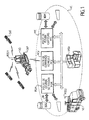
- the demining installation comprises a demining vehicle VD, a vehicle VC, and, where appropriate, logistical support (not shown)
- the demining vehicle VD may be of the teleoperated type (ie remotely controlled), autonomous, or semi-autonomous. He is generally unmanned, but he can be driven manually.
- the VC control vehicle includes a management station PGM mission, a control station for the VD demining vehicle, and, if applicable, a PFC data merge station emanating from CAP mine detection sensors.
- the PGM Mission Management position ensures the preparation and management of the demining mission, including the use of IG geographical information from databases BDG.
- the control station of the demining vehicle controls the moving the demining vehicle VD using information especially from the means of positioning and centimeter guidance which will be described in more detail below.
- the PFC Data Merge Station processes the information emanating from the mine detection sensors CAP of the vehicle of demining VD. This information can be processed in link with a BDM database.
- the PGM, PCV and PFC stations are advantageously equipped with a VISU visualization system.
- Each of the tasks of the vehicle control (mission management, vehicle control, and fusion data) is assumed by at least one operator.
- the control vehicle VC is for example built from a wheeled vehicle weighing approximately 10 to 12 tonnes.
- control vehicle VC is located in outside the danger zone to protect it from bursts of mine clearance.
- Logistics support (not shown) is intended to ensure energy production. It includes, where appropriate, a maintenance workshop for light systems.
- the vehicle of demining is of the teleoperated type, and takes over at least some guide elements of the vehicle described in the patent No. 95 15579 filed in the name of the Applicant and the description is an integral part of this Application for all purposes.
- the demining vehicle is equipped with means of shooting (CA1, CA2, CA3 cameras) to record images from the environment in which the VD demining vehicle is moves.
- Means for transmitting / receiving video information AVT are also planned to transmit the images as well registered to the VC control vehicle, as well as the information delivered by active means and sensors of the demining vehicle and to receive instructions from control (of the engine and steering demining) from the operator via the control vehicle.
- the centimeter positioning and guiding means of the demining vehicle VD include a receiver DGPS type POS1, at least one ODO odometer, and a central inertial INE.
- two ODO odometers are provided to provide a measurement of longitudinal displacement (velocity measurement) demining vehicle.
- an ODO odometer is placed in each caterpillar DEP training of demining vehicle VD.
- the INE inertial unit provides a measure of the three attitude angles of the vehicle (a relative yaw, and the absolute roll and pitch), as well as a measure of the accelerations following the three axes of the vehicle.
- Positioning system is GPS or GLONASS in which SAT satellites (FIG. 1) emit waves carriers marked temporally by pseudo-random codes.
- the positioning system is of the type Differential DGPS. It delivers a centimeter measurement of the absolute position of the POS1 antenna placed on the vehicle of demining. This POS1 antenna is called mobile.
- a stationary POS2 antenna found installed at the VC control vehicle. This POS2 antenna is arranged at a point whose coordinates are known to the nearest centimeter.
- the corrections of the GPS positioning system are transmitted from the antenna POS2 to the antenna POS1 via a UHF radio link.
- An AUHF antenna is placed on demining vehicles VD and VC control.
- the method of calculating the centimeter position of the vehicle demining is of the LRK type for "Long Range Kinematic". This process uses the two frequencies of the GPS system called L1 and L2.
- a first approximate solution is calculated by a method recursive using pseudo-distances and triples phase differences on the L1 frequency, as well as the triple phase differences on the L2 frequency and the pseudo-distances on L1 / L2.
- the final solution is then calculated from the approximate solution by solving in two iterations of a difference equation.
- Such a positioning system is for example sold under the reference "AQUARIUS" by the French company DASSAULT SERCEL NAVIGATION and POSITIONING.
- the demining vehicle VD is preferably built to from a public works machine (such as sold by CATERPILLAR under the reference D3C CAT or 939 CAT).
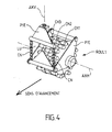
- bearing means ROUL1 and ROUL2 are arranged in front of the vehicle.
- These rolling means are for example rotary mounted metal rollers or wheels relative to a horizontal axis.
- rolling means ROUL are for example supported by arms BR1, and BR2 mounted pivoting around a horizontal axis AXH.
- These means of Rolling bearing can be similar to those usually used in the first demining technique mentioned in the introduction of this Application. They stand out by the fact that they do not cover the entire width of the demining vehicle but only two running surfaces a few tens of cm each, spaced one from the other from a distance of the order of 1 to 2 m.
- rolling means rolling comprises three steel chains independent of each other and mounted on parallel axes between them. These chains, individualized in CH1 to CH3 form steel wheels allowing simulate the rolling of a caterpillar.
- a piece PIE ( Figure 4 or 5) is intended to secure the rolling means with traction and lifting arms BR1, BR2 and LEV of the demining vehicle VD.
- This piece PIE is rotatably mounted around a vertical axis AXV in order to allow rotation of the rolling means when the demining vehicle VD swings around a vertical axis.
- the piece PIE thus allows the movement of rolling means. This movement is guided by the axis AXV which moves in a LU light defined for example by CN chains.
- the LU light is secured to the traction arms BR1 and BR2 (FIG. 5).
- BR1 traction arms and BR2 are also integral with the LEV lift arms of the VD vehicle that can be of the type of public works machine.
- the rolling surfaces of the means of bearing are likely to leave two traces on the ground to clear.
- the pressure applied by the means of rolling on the floor is chosen to allow the destruction mechanics of a low power mine.
- TON cleaning means are also arranged at the front of the brushcutter at a height selected by relative to the surface of the land, the land between first and second rolling means ROUL1 and ROUL2 during the removal of the demining vehicle.
- the TON cleaning means comprise a mower type system, roto-grinder, or cutting blade clean to rotate around a horizontal axis at a height chosen in relation to the surface of the ground.
- the blade consists of a rotor with steel flails or knife spoons.
- Means of recovery of waste REC can where appropriate, be provided for the recovery of waste brushing.
- These REC recovery means are by example of suction means adapted to the means of TON cleaning to recover residues from the cut and reject them in a receptacle (not shown) attached to the demining vehicle.
- the demining vehicle VD can accommodate means of CAP mine detection, CAPM magnetic sensor type, CAPT infrared thermal camera, and radar detection by internal imaging of the soil (not shown).
- the detection means CAP are preferably arranged at the rear of the vehicle so as not to be damaged by the explosion of a mine during the passage of rolling means the demining vehicle.
- CAPM magnetic sensors are willing to the rear of the vehicle on a transverse bar BT equipped with several DBM teeth shaped magnetic loop.
- the VD vehicle is equipped to be of minimal cost in possession and maintenance.
- the structure of the vehicle is simplified by the removal of the elements not contributing to the demining mission.
- the weight of the demining vehicle is of the order of 10 tonnes, with a length less than or equal to 6 meters, a width less than or equal to 2.70 meters and a lower height or equal to 4 meters.
- Certain vital parts of the vehicle are protected by a light armor (from type aramid for example) against the shards of anti-personnel mines.
- the mobility devices of the vehicle are protected more significantly.
- the lower part of the vehicle of demining is heavily shielded to withstand the explosion of all types of anti-personnel mines.
- the cabin of steering is advantageously closed using windows shielded.
- an armored plate (not shown) is mounted between the roller bearing means ROUL1 and ROUL2 and the TON cleaning means to protect the vehicle from demining of mine shards exploding under the action of rolling means.
- Some more exposed constituents of the vehicle such as DEP tracks or the rolling means ROUL1 and ROUL2, are likely to be damaged by an anti-personnel mine strong power.
- these means are designed to be easily repairable and a construction technology simple, inexpensive, and easily accessible.
- CF thread cutters can also be arranged at appropriate places to cut the wires on the way the demining vehicle.
- these CF thread cutters are arranged at the front of the vehicle, downstream of the means of bearing ROUL1 and ROUL2. They can be in solidarity with chassis of the demining vehicle. They may include a CF multi-blade harrow capable of scraping the soil surface immediately following the passage of the rolling means.
- This first trip TJ1 comprises two traces TRA1 and TRA2, substantially parallel between them, left by rolling means ROUL1 and ROUL2 of the demining vehicle.
- the method of displacement provides for move the demining vehicle along a second path TJ2 field, parallel to the first path TJ1, and comprising a track TRA2 of the first path TJ1, in the opposite direction.
- the method provides for repeating the movement of the vehicle of demining to get the demining vehicle through all terrain to clear.
- demining operators can more easily and with a relatively high degree of security, intervene later on the mines that were detected during the passage of the demining vehicle.
- Step E1 consists in describing and analyzing the mission of demining, which usually includes a cleaning step and a demining step of the mines detected during the passage of the demining vehicle when cleaning the ground.
- Step E2 is to identify the area to be cleared.
- GI geographical information of the area from example of BDG geographic databases, sources SPOT satellites, ..., are used to define the area to be cleared.
- Step E3 is to identify the geographic coordinates land to clear.
- Step E4 is to prepare the mission, generating by example a scenario that indicates the route to be traveled, the duration of the mission, the action plan for the teams intervention, and the projected consumption of implemented.
- Step E5 is to load the mission scenario as well prepare.
- Step E6 is to execute the mission by ensuring the safety of demining operators, thanks to the precise demining vehicle described in detail for reference in Figure 6.
- Stage E7 provides for an end-of-mission result is used to update (step E8) the database intended to contain the results of demining missions BDG, as well as terrain maps.
- a CP card under paper form can be generated from such a setting day.
- CAP detection means When a mine is detected by the CAP detection means, CAPT, CAPM, detection information is received and validated by the data fusion operator located in the data fusion station.
- the location of the mine as well detected is marked when the vehicle passes in a material way (actual mark on the ground), and / or intangible (location kept in memory or mapping).
- the human mine clearance operation is treated in a conventional way, for example according to force.
- the demining vehicle can be a simple public works vehicle in front of which are mounted cleaning means as well as means of rolling.
- the equipment of the demining vehicle is completed by detection means located advantageously at the rear.
- Such a demining vehicle is very light compared armored vehicles that are generally used for mine clearance anti-personnel mines.
- the range of the vehicle of demining according to the invention is therefore greater than that of vehicles of the prior art.
- the vehicle of demining after demining mission can be reused for functions other than demining operations, by example of type public works or handling equipment.
Landscapes
- Life Sciences & Earth Sciences (AREA)
- Engineering & Computer Science (AREA)
- Physics & Mathematics (AREA)
- Environmental & Geological Engineering (AREA)
- Geology (AREA)
- Remote Sensing (AREA)
- General Engineering & Computer Science (AREA)
- General Life Sciences & Earth Sciences (AREA)
- General Physics & Mathematics (AREA)
- Geophysics (AREA)
- Control Of Position, Course, Altitude, Or Attitude Of Moving Bodies (AREA)
- Steering-Linkage Mechanisms And Four-Wheel Steering (AREA)
- Investigation Of Foundation Soil And Reinforcement Of Foundation Soil By Compacting Or Drainage (AREA)
- Road Repair (AREA)
- Drilling And Exploitation, And Mining Machines And Methods (AREA)
Description
- la figure 1 est une vue représentant schématiquement les moyens essentiels d'une installation de déminage selon l'invention;
- la figure 2 est une vue en perspective du véhicule de déminage selon l'invention;
- les figures 3A à 3D sont différentes vues du véhicule de déminage selon l'invention;
- la figure 4 représente schématiquement les moyens de roulement du véhicule de déminage selon l'invention;
- la figure 5 représente schématiquement une variante du véhicule de déminage selon l'invention avec des moyens de récupération des déchets ainsi que des moyens coupe-fils;
- la figure 6 illustre schématiquement le déplacement du véhicule de déminage sur un terrain à déminer selon l'invention; et
- la figure 7 représente un organigramme illustrant les différentes étapes d'une mission de déminage selon l'invention.
Claims (13)
- Procédé de déplacement d'un véhicule, en particulier pour déminage d'un terrain, caractérisé en ce qu'il comprend les étapes suivantes :a) disposer, à l'avant du véhicule de déminage (VD), des premiers et seconds moyens de roulement (ROUL1 et ROUL2), sensiblement parallèles entre eux, espacés les uns des autres d'une distance choisie, et propres à détruire mécaniquement les mines à la suite de leur passage, et des moyens de nettoyage (TON) propres à débroussailler, à une hauteur choisie par rapport à la surface du terrain, le terrain situé entre les premiers et seconds moyens de roulement (ROUL1 et ROUL2),b) équiper le véhicule de déminage (VD) de moyens de positionnement (POS1) et de guidage (ODO, INE) centimétrique,c) déplacer le véhicule de déminage (VD) selon un premier trajet (TJ1) du terrain à déminer, les premiers et seconds moyens de roulement (ROUL1 et ROUL2) laissant chacun une trace (TRA1 et TRA2) à la suite de leur passage,d) déplacer le véhicule de déminage (VD) selon un second trajet (TJ2) du terrain, sensiblement parallèle au premier trajet (TJ1) et comprenant une trace (TRA2) du premier trajet (TJ1), dans le sens opposé, ete) répéter l'étape d) jusqu'à faire passer le véhicule de déminage sur tout le terrain à déminer.
- Procédé selon la revendication 1, caractérisé en ce que l'étape a) consiste en outre à disposer à l'arrière du véhicule de déminage (VD) des moyens de détection de mines (CAP), et en ce que le procédé comprend en outre l'étape f) consistant à construire une carte des mines ainsi détectées lors du déplacement du véhicule (VD) sur tout le terrain.
- Installation pour le déplacement précis d'un véhicule sur un terrain, en particulier un véhicule de déminage, caractérisée en ce que le véhicule de déminage (VD) comprend:à l'avant du véhicule de déminage (VD), des premiers et seconds moyens de roulement (ROUL1 et ROUL2), sensiblement parallèles entre eux, espacés les uns des autres d'une distance choisie, et propres à détruire mécaniquement les mines à la suite de leur passage,des moyens de nettoyage (TON) propres à débroussailler, à une hauteur choisie par rapport à la surface du terrain, le terrain situé entre les premiers et seconds moyens de roulement (ROUL1 et ROUL2),des moyens de positionnement (POS1) et de guidage (ODO,INE) centimétrique propre à déplacer le véhicule de déminage (VD) selon un premier trajet (TJ1) du terrain à déminer, les premiers et seconds moyens de roulement (ROUL1 et ROUL2) laissant chacun une trace (TRA1, et TRA2) à la suite de leur passage, et selon un second trajet (TJ2) du terrain, parallèle au premier trajet (TJ1) et comprenant une trace (TRA2) du premier trajet (TJ1), dans le sens opposé.
- Installation selon la revendication 3, caractérisée en ce que le véhicule de déminage (VD) comprend en outre des moyens de détection de mines (CAP,CAPM,CAPT), disposés à l'arrière du véhicule de déminage (VD), et ce que le dispositif comprend en outre des moyens propres à construire une carte des mines ainsi détectées lors du déplacement du véhicule de déminage sur tout le terrain.
- Installation selon la revendication 3, caractérisée en ce que les moyens de nettoyage (TON) comprennent au moins un outil de type lame de coupe ou roto-broyeur apte à tourner autour d'un axe horizontal à une hauteur choisie par rapport à la surface horizontale du terrain.
- Installation selon la revendication 3, caractérisée en ce que le véhicule de déminage (VD) est du type autonome, ou semi-autonome, avec ou sans pilote.
- Installation selon la revendication 3, caractérisée en ce que le véhicule de déminage (VD) est du type télé-opéré.
- Installation selon la revendication 7, caractérisée en ce qu'il comprend en outre un véhicule de commande (VC) propre à communiquer à distance avec le véhicule de déminage (VD) afin de commander le déplacement du véhicule de déminage (VD) selon les premier et second trajets (TJ1 et TJ2).
- Installation selon la revendication 8, caractérisée en ce que le véhicule de commande (VC) comprend un poste de gestion de mission de déminage (PGM), un poste de commande du véhicule de déminage (PCV,POS2) communiquant avec les moyens de positionnement (POS1) et de guidage (ODO,INE) du véhicule de déminage (VD), et un poste de fusion de données émanant des moyens de détection des mines (CAP,CAPM,CAPT).
- Installation selon la revendication 9, caractérisée en ce que le poste de gestion de mission (PGM) utilise des informations géographiques (IG) délivrées par une base de données géographiques (BDG).
- Installation selon la revendication 9, caractérisée en ce que le poste de fusion de données (PFC) délivre des informations de localisation de mines (CP) en vue d'une reconnaissance du terrain.
- Installation selon la revendication 3, caractérisée en ce que les moyens de positionnement et de guidage centimétrique du véhicule de déminage (VD) comprennent un récepteur (POS1) de type GPS, au moins un odomètre (ODO), et une centrale inertielle (INE).
- Installation selon la revendication 3, caractérisée en ce que le poids du véhicule de déminage (VD) est de l'ordre de 10 tonnes.
Applications Claiming Priority (2)
| Application Number | Priority Date | Filing Date | Title |
|---|---|---|---|
| FR9814849A FR2786263B1 (fr) | 1998-11-25 | 1998-11-25 | Procede et installation de deplacement precis d'un vehicule sur un terrain, en particulier un vehicule de deminage |
| FR9814849 | 1998-11-25 |
Publications (2)
| Publication Number | Publication Date |
|---|---|
| EP1004845A1 EP1004845A1 (fr) | 2000-05-31 |
| EP1004845B1 true EP1004845B1 (fr) | 2003-02-12 |
Family
ID=9533175
Family Applications (1)
| Application Number | Title | Priority Date | Filing Date |
|---|---|---|---|
| EP99402894A Expired - Lifetime EP1004845B1 (fr) | 1998-11-25 | 1999-11-22 | Procédé et installation pour le déplacement précis d'un véhicule sur un terrain en particulier un véhicule de déminage |
Country Status (4)
| Country | Link |
|---|---|
| EP (1) | EP1004845B1 (fr) |
| AT (1) | ATE232596T1 (fr) |
| DE (1) | DE69905331T2 (fr) |
| FR (1) | FR2786263B1 (fr) |
Families Citing this family (8)
| Publication number | Priority date | Publication date | Assignee | Title |
|---|---|---|---|---|
| RU2205351C1 (ru) * | 2001-11-14 | 2003-05-27 | Общевойсковая Академия Вооруженных Сил Российской Федерации | Сочлененная инженерная разведывательная машина |
| WO2003091653A2 (fr) * | 2002-04-26 | 2003-11-06 | Inter-Continental Safety Systems Inc. | Procede et processeur servant a enlever des engins explosifs d'une zone de sol |
| FR2843452B1 (fr) * | 2002-08-07 | 2004-09-24 | Const Ind De La Mediterranee | Systeme de deminage pour mines terrestres |
| DE10255254A1 (de) * | 2002-11-27 | 2004-06-17 | Rheinmetall Landsysteme Gmbh | Minenräumfahrzeug |
| DE102004003055A1 (de) * | 2004-01-20 | 2005-08-18 | Rheinmetall Landsysteme Gmbh | Anordnung von einem ersten und mindestens einem weiteren Fahrzeug in einem lose koppelbaren nicht spurgebundenen Zugverband |
| US7685917B2 (en) * | 2005-04-22 | 2010-03-30 | Humanistic Robotics, Inc. | Apparatus and method for clearing land mines |
| DE102007002976A1 (de) * | 2007-01-19 | 2008-07-24 | Krauss-Maffei Wegmann Gmbh & Co. Kg | Verfahren zur Fernsteuerung eines Waffensystems |
| US8763506B2 (en) | 2007-09-20 | 2014-07-01 | Humanistic Robotics | Roller system |
Family Cites Families (9)
| Publication number | Priority date | Publication date | Assignee | Title |
|---|---|---|---|---|
| US5307272A (en) * | 1991-08-19 | 1994-04-26 | The United States Of America As Represented By The United States Department Of Energy | Minefield reconnaissance and detector system |
| DE4242541C2 (de) * | 1992-12-16 | 1996-03-28 | Tzn Forschung & Entwicklung | Vorrichtung zum Orten von unterhalb der Erdoberfläche befindlicher Munition |
| FR2708729B1 (fr) * | 1993-07-30 | 1995-09-22 | Giat Ind Sa | Système de déminage, en particulier pour des mines de surface du type à plateau de pression. |
| DE4417262A1 (de) * | 1994-05-17 | 1995-11-23 | Daimler Benz Aerospace Ag | System zur Ortung von Objekten und/oder zur Bergung und/oder Bearbeitung dieser georteten Objekte |
| DE4423623C2 (de) * | 1994-07-06 | 1997-12-04 | Foerster Inst Dr Friedrich | Verfahren und System zur Altlastendetektion |
| US5592170A (en) * | 1995-04-11 | 1997-01-07 | Jaycor | Radar system and method for detecting and discriminating targets from a safe distance |
| DE19514569A1 (de) * | 1995-04-20 | 1996-10-24 | Wegmann & Co Gmbh | An einem Trägerfahrzeug, insbesondere einem Kampfpanzer, installierte Such- und Räumeinrichtung für Landminen, sowie Verfahren zur Ortung und Zerstörung einer Landmine mittels dieser Such- und Räumeinrichtung |
| DE19540961A1 (de) * | 1995-10-21 | 1997-04-24 | Foerster Inst Dr Friedrich | Fahrbarer Sondenträger |
| FR2743162B1 (fr) | 1995-12-27 | 1998-05-07 | Dassault Electronique | Dispositif de commande pour la securisation d'un vehicule rapide, notamment guide par un operateur embarque ou non dans ledit vehicule |
-
1998
- 1998-11-25 FR FR9814849A patent/FR2786263B1/fr not_active Expired - Fee Related
-
1999
- 1999-11-22 DE DE69905331T patent/DE69905331T2/de not_active Expired - Lifetime
- 1999-11-22 EP EP99402894A patent/EP1004845B1/fr not_active Expired - Lifetime
- 1999-11-22 AT AT99402894T patent/ATE232596T1/de not_active IP Right Cessation
Also Published As
| Publication number | Publication date |
|---|---|
| DE69905331T2 (de) | 2003-09-11 |
| EP1004845A1 (fr) | 2000-05-31 |
| DE69905331D1 (de) | 2003-03-20 |
| FR2786263A1 (fr) | 2000-05-26 |
| FR2786263B1 (fr) | 2001-01-12 |
| ATE232596T1 (de) | 2003-02-15 |
Similar Documents
| Publication | Publication Date | Title |
|---|---|---|
| US12346111B2 (en) | Autonomous path treatment systems and methods | |
| Jones et al. | Design and testing of a heavy-duty platform for autonomous navigation in kiwifruit orchards | |
| EP2300888B1 (fr) | Dispositif de commande d'appareil(s) mobile(s) autopropulsé(s) | |
| BE1012440A3 (fr) | Procede de recolte. | |
| Habib | Humanitarian demining: reality and the challenge of technology–the state of the arts | |
| US20180035606A1 (en) | Smart Interactive and Autonomous Robotic Property Maintenance Apparatus, System, and Method | |
| US20230305565A1 (en) | System for detection, collection, and remediation of objects of value at waste, storage, and recycling facilities | |
| EP3887256B1 (fr) | Appareil de maintenance de piste | |
| EP1004845B1 (fr) | Procédé et installation pour le déplacement précis d'un véhicule sur un terrain en particulier un véhicule de déminage | |
| US20230249351A1 (en) | Fastener system and method | |
| IL193216A (en) | Suspicious zone detection system | |
| FR2944111A1 (fr) | Procede et systeme de saisie de l'environnement | |
| CN110612242B (zh) | 在高速情况下进行除草 | |
| AU2017305597A1 (en) | Smart interactive and autonomous robotic property maintenance apparatus, system, and method | |
| US20250287858A1 (en) | Systems and methods for improved operation of a working vehicle | |
| EP3273201B2 (fr) | Methode de calcul d'un itineraire pour un engin tout terrain | |
| Trautmann et al. | Development of an autonomous robot for ground penetrating radar surveys of polar ice | |
| EP3359927B1 (fr) | Dispositif mobile pour le contrôle et/ou la maintenance d'au moins un équipement d'une zone aéroportuaire, système et procédé correspondants | |
| Baudoin | Mobile robotic systems facing the humanitarian demining problem State of the Art (SOTA) December 2007 ITEP 3.1. 4 Task | |
| FR3101412A1 (fr) | Système d’ouverture d’itinéraire pour la sécurisation de convoi et véhicule équipé d’un tel système | |
| EP2767818B1 (fr) | Système de diagnostic de l'état structurel d'une unité de roulement d'un engin à roues sur une voie, comprenant des antennes ponctuelles émettrice et réceptrice. | |
| Baudoin et al. | Introduction: Mobile robotics systems for humanitarian de-mining and risky interventions | |
| Le Gusquet et al. | A Franco-German unmanned countermine system demonstrator | |
| Hudler et al. | Remote Controlled Vehicle Mounted Minefield Detector System. | |
| FR3072488A1 (fr) | Terminal de securite et systeme de securisation d'un site d'activite |
Legal Events
| Date | Code | Title | Description |
|---|---|---|---|
| PUAI | Public reference made under article 153(3) epc to a published international application that has entered the european phase |
Free format text: ORIGINAL CODE: 0009012 |
|
| AK | Designated contracting states |
Kind code of ref document: A1 Designated state(s): AT BE CH CY DE DK ES FI FR GB GR IE IT LI LU MC NL PT SE |
|
| AX | Request for extension of the european patent |
Free format text: AL;LT;LV;MK;RO;SI |
|
| 17P | Request for examination filed |
Effective date: 20001129 |
|
| AKX | Designation fees paid |
Free format text: AT BE CH CY DE DK ES FI FR GB GR IE IT LI LU MC NL PT SE |
|
| GRAG | Despatch of communication of intention to grant |
Free format text: ORIGINAL CODE: EPIDOS AGRA |
|
| 17Q | First examination report despatched |
Effective date: 20020416 |
|
| GRAG | Despatch of communication of intention to grant |
Free format text: ORIGINAL CODE: EPIDOS AGRA |
|
| GRAH | Despatch of communication of intention to grant a patent |
Free format text: ORIGINAL CODE: EPIDOS IGRA |
|
| GRAH | Despatch of communication of intention to grant a patent |
Free format text: ORIGINAL CODE: EPIDOS IGRA |
|
| RAP1 | Party data changed (applicant data changed or rights of an application transferred) |
Owner name: THALES SYSTEMES AEROPORTES S.A. |
|
| GRAA | (expected) grant |
Free format text: ORIGINAL CODE: 0009210 |
|
| AK | Designated contracting states |
Designated state(s): AT BE CH CY DE DK ES FI FR GB GR IE IT LI LU MC NL PT SE |
|
| PG25 | Lapsed in a contracting state [announced via postgrant information from national office to epo] |
Ref country code: NL Free format text: LAPSE BECAUSE OF FAILURE TO SUBMIT A TRANSLATION OF THE DESCRIPTION OR TO PAY THE FEE WITHIN THE PRESCRIBED TIME-LIMIT Effective date: 20030212 Ref country code: IE Free format text: LAPSE BECAUSE OF FAILURE TO SUBMIT A TRANSLATION OF THE DESCRIPTION OR TO PAY THE FEE WITHIN THE PRESCRIBED TIME-LIMIT Effective date: 20030212 Ref country code: GR Free format text: LAPSE BECAUSE OF FAILURE TO SUBMIT A TRANSLATION OF THE DESCRIPTION OR TO PAY THE FEE WITHIN THE PRESCRIBED TIME-LIMIT Effective date: 20030212 Ref country code: FI Free format text: LAPSE BECAUSE OF FAILURE TO SUBMIT A TRANSLATION OF THE DESCRIPTION OR TO PAY THE FEE WITHIN THE PRESCRIBED TIME-LIMIT Effective date: 20030212 Ref country code: AT Free format text: LAPSE BECAUSE OF FAILURE TO SUBMIT A TRANSLATION OF THE DESCRIPTION OR TO PAY THE FEE WITHIN THE PRESCRIBED TIME-LIMIT Effective date: 20030212 |
|
| REG | Reference to a national code |
Ref country code: GB Ref legal event code: FG4D Free format text: NOT ENGLISH |
|
| REG | Reference to a national code |
Ref country code: CH Ref legal event code: EP |
|
| REF | Corresponds to: |
Ref document number: 69905331 Country of ref document: DE Date of ref document: 20030320 Kind code of ref document: P |
|
| PG25 | Lapsed in a contracting state [announced via postgrant information from national office to epo] |
Ref country code: SE Free format text: LAPSE BECAUSE OF FAILURE TO SUBMIT A TRANSLATION OF THE DESCRIPTION OR TO PAY THE FEE WITHIN THE PRESCRIBED TIME-LIMIT Effective date: 20030512 Ref country code: PT Free format text: LAPSE BECAUSE OF FAILURE TO SUBMIT A TRANSLATION OF THE DESCRIPTION OR TO PAY THE FEE WITHIN THE PRESCRIBED TIME-LIMIT Effective date: 20030512 Ref country code: DK Free format text: LAPSE BECAUSE OF FAILURE TO SUBMIT A TRANSLATION OF THE DESCRIPTION OR TO PAY THE FEE WITHIN THE PRESCRIBED TIME-LIMIT Effective date: 20030512 |
|
| NLV1 | Nl: lapsed or annulled due to failure to fulfill the requirements of art. 29p and 29m of the patents act | ||
| REG | Reference to a national code |
Ref country code: IE Ref legal event code: FG4D Free format text: FRENCH |
|
| GBT | Gb: translation of ep patent filed (gb section 77(6)(a)/1977) | ||
| PG25 | Lapsed in a contracting state [announced via postgrant information from national office to epo] |
Ref country code: ES Free format text: LAPSE BECAUSE OF FAILURE TO SUBMIT A TRANSLATION OF THE DESCRIPTION OR TO PAY THE FEE WITHIN THE PRESCRIBED TIME-LIMIT Effective date: 20030828 |
|
| REG | Reference to a national code |
Ref country code: IE Ref legal event code: FD4D Ref document number: 1004845E Country of ref document: IE |
|
| PG25 | Lapsed in a contracting state [announced via postgrant information from national office to epo] |
Ref country code: LU Free format text: LAPSE BECAUSE OF NON-PAYMENT OF DUE FEES Effective date: 20031122 Ref country code: CY Free format text: LAPSE BECAUSE OF FAILURE TO SUBMIT A TRANSLATION OF THE DESCRIPTION OR TO PAY THE FEE WITHIN THE PRESCRIBED TIME-LIMIT Effective date: 20031122 |
|
| PG25 | Lapsed in a contracting state [announced via postgrant information from national office to epo] |
Ref country code: MC Free format text: LAPSE BECAUSE OF NON-PAYMENT OF DUE FEES Effective date: 20031130 Ref country code: LI Free format text: LAPSE BECAUSE OF NON-PAYMENT OF DUE FEES Effective date: 20031130 Ref country code: CH Free format text: LAPSE BECAUSE OF NON-PAYMENT OF DUE FEES Effective date: 20031130 Ref country code: BE Free format text: LAPSE BECAUSE OF NON-PAYMENT OF DUE FEES Effective date: 20031130 |
|
| PLBE | No opposition filed within time limit |
Free format text: ORIGINAL CODE: 0009261 |
|
| STAA | Information on the status of an ep patent application or granted ep patent |
Free format text: STATUS: NO OPPOSITION FILED WITHIN TIME LIMIT |
|
| 26N | No opposition filed |
Effective date: 20031113 |
|
| BERE | Be: lapsed |
Owner name: S.A. *THALES SYSTEMES AEROPORTES Effective date: 20031130 |
|
| REG | Reference to a national code |
Ref country code: CH Ref legal event code: PL |
|
| REG | Reference to a national code |
Ref country code: FR Ref legal event code: PLFP Year of fee payment: 17 |
|
| REG | Reference to a national code |
Ref country code: FR Ref legal event code: PLFP Year of fee payment: 18 |
|
| REG | Reference to a national code |
Ref country code: FR Ref legal event code: PLFP Year of fee payment: 19 |
|
| REG | Reference to a national code |
Ref country code: FR Ref legal event code: PLFP Year of fee payment: 20 |
|
| PGFP | Annual fee paid to national office [announced via postgrant information from national office to epo] |
Ref country code: DE Payment date: 20181106 Year of fee payment: 20 |
|
| PGFP | Annual fee paid to national office [announced via postgrant information from national office to epo] |
Ref country code: FR Payment date: 20181026 Year of fee payment: 20 Ref country code: IT Payment date: 20181122 Year of fee payment: 20 Ref country code: GB Payment date: 20181120 Year of fee payment: 20 |
|
| REG | Reference to a national code |
Ref country code: DE Ref legal event code: R071 Ref document number: 69905331 Country of ref document: DE |
|
| REG | Reference to a national code |
Ref country code: GB Ref legal event code: PE20 Expiry date: 20191121 |
|
| PG25 | Lapsed in a contracting state [announced via postgrant information from national office to epo] |
Ref country code: GB Free format text: LAPSE BECAUSE OF EXPIRATION OF PROTECTION Effective date: 20191121 |