EP1004868A2 - Appareil et méthode pour tester des modèles en flames - Google Patents
Appareil et méthode pour tester des modèles en flames Download PDFInfo
- Publication number
- EP1004868A2 EP1004868A2 EP99308709A EP99308709A EP1004868A2 EP 1004868 A2 EP1004868 A2 EP 1004868A2 EP 99308709 A EP99308709 A EP 99308709A EP 99308709 A EP99308709 A EP 99308709A EP 1004868 A2 EP1004868 A2 EP 1004868A2
- Authority
- EP
- European Patent Office
- Prior art keywords
- flame
- model
- flow
- component
- temperature
- Prior art date
- Legal status (The legal status is an assumption and is not a legal conclusion. Google has not performed a legal analysis and makes no representation as to the accuracy of the status listed.)
- Granted
Links
Images


Classifications
-
- G—PHYSICS
- G01—MEASURING; TESTING
- G01N—INVESTIGATING OR ANALYSING MATERIALS BY DETERMINING THEIR CHEMICAL OR PHYSICAL PROPERTIES
- G01N25/00—Investigating or analyzing materials by the use of thermal means
- G01N25/50—Investigating or analyzing materials by the use of thermal means by investigating flash-point; by investigating explosibility
Definitions
- This invention relates to the evaluation of the fire resistance of components, in particular for air worthiness compliance of components in and around aircraft engines, although it can be applicable to fire resistance evaluations for other purposes.
- Air worthiness regulations require the testing of critical components to ensure that fire in and around aircraft engines does not hazard aircraft safety.
- the components are subjected to flame attack from a standard flame, to evaluate an in-service fire event.
- An array of thermocouples are mounted on the surface of the component and the maximum temperatures recorded from the test are used to determine the viability of the component during a fire event. This can be by reference to induced thermal stresses or degradation of the material, eg. deformation, oxidation or melting.
- thermocouple array The process is also expensive and time-consuming, particularly if a component initially fails the test and must be redesigned. This can lead to overdesign of a component due to excessive caution, with resulting cost and weight penalties.
- the present invention is concerned with the development of a modelling system which allows fire resistance tests to be performed more rapidly and more economically. It is also concerned with the provision of a low-temperature heating device that can simulate the designated flame source of a standard test technique.
- a method for evaluating the resistance of a component to a fire in which a scale model of the component is provided with a thermochromic liquid crystal on its surface and is subjected to a gas flow at an elevated temperature closer to ambient than to a hydrocarbon flame temperature, the gas density, flow rate and the scale of the model being chosen to at least substantially match the Reynolds number and Froude number of the flow over the component in the fire test conditions, and to at least substantially match the ratio of flame density to the density of the ambient surrounding in fire test conditions, and the reaction of said liquid crystal is recorded when subjected to the gas flow.
- the gas flow contains at least a substantial portion of a gas lighter than air.
- it may contain helium as a major component.
- a flame simulation device for use in low temperature simulation of a standard flame of a fire resistance test, comprising respective sources of pressure air and helium and means for producing a mixed flow therefrom in predetermined proportions and heating said flow, a duct for receiving said flow and simulating a standard test burner, said duct having an exit face formed by a plate with a series of apertures for the passage of the heated mixed gases, said apertures having an area in relation to the area of the duct downstream of the plate which produces a change of momentum flux in said flow substantially reproducing the ratio of the momentum flux of the standard flame combustion products to the momentum flux of the reactants on entry to the standard burner.
- the current testing procedure presumes not only that the design of the component has been finalised, but also that production tooling has been made available. Apart from the costs of the tests, therefore, if the component fails there can be serious consequences in terms of delay and cost. These could be avoided if a model test procedure was available that could be performed on an easily produced model that could be made available even before finalisation of the design, and that permitted testing at lower temperatures without exposure to a burner flame.
- a cylindrical burner head 30 has a front plate 32 provided with a first set of holes 34 receiving pipes (not shown) through which propane is supplied, and a further set of holes 36 through which air flows. Combustion between the fuel and air occurs in a zone 38 downstream of the plate and the flame plume extends upwards from the combustion zone.
- the spreading of the flame and its mixing with the surroundings will be governed by the relative magnitude of the flame density ( ⁇ f ) to that of its ambient surroundings ( ⁇ o ).
- the inlet flow is formed as a series of jets, from the propane delivery pipes and from the air inlet holes respectively.
- the fuel thus burns in discrete jets and the combustion products mix with the dilution air until the flows are mixed out.
- the flow over the path from the exit of the jets from the apertured plate 32 to the mixed out state can be represented as a control volume 40, shown as a constant cross-section in Fig. 4. From the inlet face 42 to the outlet face 44 of the control volume there will be a change of momentum flux from two different causes.
- the flow area through the plate is less than the flow area further downstream in the control volume.
- the associated decrease in velocity decreases the momentum flux.
- the momentum flux is a function of the hole diameter d and the number of holes n. That is to say, the total momentum flux at the hole exits, which equals the product of the mass flow rate ( m h ) and flow velocity (u h ) through the holes is 4 m 2 n ⁇ d 2
- the combination of the two parameters n and d is effectively the porosity of the face plate as the diameter of the plate is already specified.
- the positioning of the holes will also influence the shape of the plume, but as individual jets of sufficiently small diameter will quickly coalesce into a single larger plume, it is sufficient to simply reproduce the overall plume diameter.
- the momentum flux can therefore be scaled by conserving the ratio of the momentum fluxes of the upstream and downstream flows. If the low temperature model flow does not require combustion, the two pre-combustion and combustion influences on the momentum flux as described above can be simulated jointly by a single series of holes in the model burner face plate, if the porosity is suitably adjusted. That is to say, the ratio of the area of the apertures to the area of the duct downstream of the apertures (or, more strictly, the area occupied by the flow when the aperture jets mix out) is controlled to scale the momentum flux ratio.
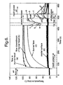
- Fig. 5 illustrates the test rig for the simulated flame test of a model component applying the principles discussed above.
- Perspex was chosen as a suitable material for the model of the rear mount support ring, having well defined properties. As Perspex is usable for an extended period only at temperatures below 90°C, a gas temperature of 80°C was selected for the simulated flame flow. In order to achieve the required density ratio at such a low temperature, if air were used for the simulated flame, the test rig would have to be immersed in a higher density atmosphere. To avoid that inconvenience, a reduced density simulated flow was produced so that it was not necessary to adjust the density of the surroundings. In the testing described here, a mixture of 96% helium and 4% air was used for the simulated gas flow.
- FIG. 5 shows, flows from air and helium sources, 50,52 regulated by meters 54, were fed to a heating chamber 56 forming an exit duct 58 at the exit face of which is a perforated plate 60 which scaled the porosity the standard flame burner as already described.
- a fast response mesh heater 62 was able to heat the air-helium mixture before it reached the exit plate.
- the heated gas flow was directed onto a half scale Perspex model ⁇ of the test component, to the surface of which a thermochromic liquid crystal had been applied, mounted on a support 64 in front of the plate.
- a shutter 66 was able to screen the model initially from the flow while the plate temperature is being equilibrated.
- Video cameras 68 trained on the model were located at each side of the chamber and a further video camera 68a viewed the model directly from the chamber, for which the purpose the perforated plate was of a transparent material such as polycarbonate.
- Lighting 70 was provided, as appropriate, to illuminate the model for the cameras.
- the contours of recorded change in the liquid crystal on the model surface which were themselves isotherms, represented contours of constant heat transfer coefficients.
- the local heat transfer coefficient h was thus a function only of the driving temperature difference ( T g -T i ), the crystal change temperature ( T c ), the material properties of the substrate ( ⁇ ck ) and the time ( t ) at which the contour appeared.
- the adiabatic wall temperature In the core of the simulated flame playing on the model, the adiabatic wall temperature equals the gas temperature T g which is nominally uniform, but at the edges of the flame the hot gas mixes with the surrounding air, reducing T g .
- T g gas temperature
- T c transition temperature
- the degree of mixing between the surrounding air and the heated gas plume in the model is approximately the same as for the standard flame, since the fluid dynamics have been matched, but the temperature in the mixed region will not be correct as the procedure does not reproduce the temperature and specific heat ratios T plume T o and C p,plume C p,o
- Tm C p,f,Tf .T f .M f + C p,o,To T o .M o
- the local specific heats of the two components are determined iteratively with the local gas temperature.
- the modelling technique described above is designed to conserve the non-dimensional heat transfer coefficients between the hot standard flame and the cold simulation.
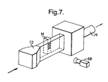
- the metal temperatures deduced from the fire tests are also a function of the cooling flow on the rear of the component. While the flow across the rear of the component is essentially a standard duct flow, no accurate correlations exist in the literature for the convection in the cavities on the rear surface. The distribution of surface heat transfer coefficient can however be determined in these regions experimentally.
- Fig. 7 illustrates a modification of the set-up of Fig. 5 for measurement in the model of heat transfer coefficient distribution in rear cavities. It will be seen that the heated flow of the gas mixture as before is led through a duct 72 past the face of the model under investigation by means of a pumped suction flow drawn through exhaust conduit 74. Reproduction of the flame plume configuration is not relevant to these tests.
- a comparison of the measured levels of h on the wall of the mount ring, away from the cavities, may be made using the correlation of Dittus and Boelter (1930) for fully developed turbulent flow in smooth tubes.
- Nu d 0.023 Re d 0.8 Pr 0.4 where Re d is based on the hydraulic diameter, and all the fluid properties are determined at the bulk temperature.
- the bulk temperature may reasonably be taken as the entry temperature.
- Radiative heat transfer can be calculated in the finite element analysis at all external surfaces of the component in the numerical model using an accurate, experimentally determined, value for the emissivity of the metal (as a function of surface temperature). Internal radiation between facing surfaces can also be accounted for in the numerical model.
Landscapes
- Physics & Mathematics (AREA)
- Health & Medical Sciences (AREA)
- Life Sciences & Earth Sciences (AREA)
- Chemical & Material Sciences (AREA)
- Analytical Chemistry (AREA)
- Biochemistry (AREA)
- General Health & Medical Sciences (AREA)
- General Physics & Mathematics (AREA)
- Immunology (AREA)
- Pathology (AREA)
- Investigating Or Analyzing Materials Using Thermal Means (AREA)
Applications Claiming Priority (2)
| Application Number | Priority Date | Filing Date | Title |
|---|---|---|---|
| GBGB9825624.1A GB9825624D0 (en) | 1998-11-23 | 1998-11-23 | Model test apparatus and method |
| GB9825624 | 1998-11-23 |
Publications (3)
| Publication Number | Publication Date |
|---|---|
| EP1004868A2 true EP1004868A2 (fr) | 2000-05-31 |
| EP1004868A3 EP1004868A3 (fr) | 2001-08-29 |
| EP1004868B1 EP1004868B1 (fr) | 2008-09-10 |
Family
ID=10842883
Family Applications (1)
| Application Number | Title | Priority Date | Filing Date |
|---|---|---|---|
| EP99308709A Expired - Lifetime EP1004868B1 (fr) | 1998-11-23 | 1999-11-02 | Appareil et méthode pour tester des modèles en flames |
Country Status (4)
| Country | Link |
|---|---|
| US (1) | US6418806B1 (fr) |
| EP (1) | EP1004868B1 (fr) |
| DE (1) | DE69939519D1 (fr) |
| GB (1) | GB9825624D0 (fr) |
Cited By (2)
| Publication number | Priority date | Publication date | Assignee | Title |
|---|---|---|---|---|
| EP1281954A1 (fr) * | 2001-07-30 | 2003-02-05 | General Electric Company | Méthode et dispositif pour mesurer la distribution locale d'échange de chaleur sur une surface |
| CN109603941A (zh) * | 2019-01-11 | 2019-04-12 | 京东方科技集团股份有限公司 | 微流控芯片系统及微流控芯片 |
Families Citing this family (7)
| Publication number | Priority date | Publication date | Assignee | Title |
|---|---|---|---|---|
| US20070132898A1 (en) * | 2005-11-04 | 2007-06-14 | Union College | Light transmission based liquid crystal temperature sensor |
| WO2008065213A2 (fr) * | 2006-11-29 | 2008-06-05 | Airbus España, S.L. | Procédés et systèmes de simulation thermique pour l'analyse du feu dans des objets |
| US8577626B2 (en) * | 2008-07-22 | 2013-11-05 | General Electric Company | System and method for assessing fluid dynamics |
| US11255537B2 (en) * | 2016-07-08 | 2022-02-22 | Nova Chemicals (International) S.A. | Metallic burner tiles |
| CN111947802B (zh) * | 2020-07-06 | 2022-06-03 | 深圳供电局有限公司 | 电气连接接头温度预警装置 |
| CN112986173B (zh) * | 2021-03-18 | 2022-04-22 | 西南交通大学 | 超高海拔隧道火灾一氧化碳浓度的获得方法 |
| CN114002265B (zh) * | 2021-11-01 | 2024-11-22 | 重庆工商大学 | 点源激发表面热波耦合红外成像的壁体材料热扩散率及局部换热系数测量方法 |
Family Cites Families (9)
| Publication number | Priority date | Publication date | Assignee | Title |
|---|---|---|---|---|
| DE2527618C2 (de) * | 1975-06-20 | 1985-09-26 | Fritz Dr.-Ing. 8026 Ebenhausen Schoppe | Verfahren und Vorrichtung zur Verbrennung von Kohlenstaub |
| GB8804177D0 (en) | 1988-02-23 | 1988-03-23 | Secr Defence | Surface temperature mapping using liquid crystal materials |
| US4927357A (en) * | 1988-04-01 | 1990-05-22 | The Boc Group, Inc. | Method for gas lancing |
| US4885633A (en) | 1988-06-13 | 1989-12-05 | The United States Of America As Represented By The Administrator Of The National Aeronautics And Space Administration | Quantitative surface temperature measurement using two-color thermographic phosphors and video equipment |
| US5120784A (en) * | 1988-09-01 | 1992-06-09 | Basf Aktiengesellschaft | Heat-resistant thermoplastic molding compositions |
| US5085807A (en) * | 1989-05-15 | 1992-02-04 | Toray Industries, Inc. | Flame-retardant liquid crystal polyester composition, process for preparation thereof and injection-molded article composed thereof |
| GB2284261B (en) | 1993-11-29 | 1997-03-05 | Bicc Plc | Thermal management of electronics equipment |
| US5452210A (en) * | 1994-01-10 | 1995-09-19 | Thiokol Corporation | Method and system for evaluating gas generants and gas generators |
| US5580172A (en) | 1994-10-11 | 1996-12-03 | Solar Turbines Incorporated | Method and apparatus for producing a surface temperature map |
-
1998
- 1998-11-23 GB GBGB9825624.1A patent/GB9825624D0/en not_active Ceased
-
1999
- 1999-11-02 DE DE69939519T patent/DE69939519D1/de not_active Expired - Lifetime
- 1999-11-02 EP EP99308709A patent/EP1004868B1/fr not_active Expired - Lifetime
- 1999-11-04 US US09/433,953 patent/US6418806B1/en not_active Expired - Fee Related
Cited By (2)
| Publication number | Priority date | Publication date | Assignee | Title |
|---|---|---|---|---|
| EP1281954A1 (fr) * | 2001-07-30 | 2003-02-05 | General Electric Company | Méthode et dispositif pour mesurer la distribution locale d'échange de chaleur sur une surface |
| CN109603941A (zh) * | 2019-01-11 | 2019-04-12 | 京东方科技集团股份有限公司 | 微流控芯片系统及微流控芯片 |
Also Published As
| Publication number | Publication date |
|---|---|
| EP1004868A3 (fr) | 2001-08-29 |
| DE69939519D1 (de) | 2008-10-23 |
| GB9825624D0 (en) | 1999-01-13 |
| EP1004868B1 (fr) | 2008-09-10 |
| US6418806B1 (en) | 2002-07-16 |
Similar Documents
| Publication | Publication Date | Title |
|---|---|---|
| Rogers et al. | Experimental supersonic combustion research at NASA Langley | |
| Fischer et al. | Experimental investigation of wall and total temperature influence on a shock train | |
| US6418806B1 (en) | Model test apparatus and method | |
| Polanka et al. | Determination of cooling parameters for a high-speed, true-scale, metallic turbine vane | |
| Guo et al. | Influence of surface roughness on heat transfer and effectiveness for a fully film cooled nozzle guide vane measured by wide band liquid crystals and direct heat flux gages | |
| Cocchi et al. | Heat transfer measurements in leading-edge cooling geometry under rotating conditions | |
| Ritchie et al. | Double wall cooling of an effusion plate with simultaneous cross flow and impingement jet array internal cooling | |
| Colborn et al. | Interpreting heat flux measurements in a vitiated backward-facing step flow | |
| Magre et al. | Temperature measurements by CARS and intrusive probe in an air–hydrogen supersonic combustion | |
| Ryley et al. | Local heat transfer coefficient measurements on an engine-representative internal cooling passage | |
| Gökçen et al. | On Laminar-to-Turbulent Transition of Arc-Jet Flow in the NASA Panel Test Facility | |
| Neely et al. | Pilot study to investigate novel experimental and theoretical fire-event modelling techniques | |
| Lafont et al. | Liner multiphysics coupling between grazing flow, thermal gradients, and sound pressure levels | |
| Maqbool et al. | Measurements of film cooling performance in supersonic environments | |
| Forsyth et al. | Experimental assessment of hypersonic convective heat transfer augmentation due to surface roughness | |
| Lee | The propagation mechanism of cellular detonation | |
| Cruz et al. | Surrface and Gas-Phase Temperatures Near a Film-Cooled Wall | |
| Neely et al. | Development of the low-temperature fire event modelling technique | |
| Bakos et al. | The Mach 10 component of NASA's Hyper-X ground test program | |
| Maqbool et al. | Development of a supersonic film cooling test facility | |
| Grib et al. | Two dimensional advective heat flux estimation from velocity measurements | |
| Kirk | Near-wall reaction effects on film-cooled surface heat transfer | |
| Saavedra et al. | Scalable Heat Transfer Characterization on Film Cooled Geometries Based on Discrete Green’s Functions | |
| Prenter et al. | Measurement and prediction of hot streak profiles generated by axially opposed dilution jets | |
| Harasgama et al. | Film cooling research on the endwall of a turbine nozzle guide vane in a short duration annular cascade: Part 1—Experimental technique and results |
Legal Events
| Date | Code | Title | Description |
|---|---|---|---|
| PUAI | Public reference made under article 153(3) epc to a published international application that has entered the european phase |
Free format text: ORIGINAL CODE: 0009012 |
|
| AK | Designated contracting states |
Kind code of ref document: A2 Designated state(s): AT BE CH CY DE DK ES FI FR GB GR IE IT LI LU MC NL PT SE |
|
| AX | Request for extension of the european patent |
Free format text: AL;LT;LV;MK;RO;SI |
|
| PUAL | Search report despatched |
Free format text: ORIGINAL CODE: 0009013 |
|
| AK | Designated contracting states |
Kind code of ref document: A3 Designated state(s): AT BE CH CY DE DK ES FI FR GB GR IE IT LI LU MC NL PT SE |
|
| AX | Request for extension of the european patent |
Free format text: AL;LT;LV;MK;RO;SI |
|
| 17P | Request for examination filed |
Effective date: 20010727 |
|
| AKX | Designation fees paid |
Free format text: DE FR GB |
|
| GRAP | Despatch of communication of intention to grant a patent |
Free format text: ORIGINAL CODE: EPIDOSNIGR1 |
|
| GRAS | Grant fee paid |
Free format text: ORIGINAL CODE: EPIDOSNIGR3 |
|
| GRAA | (expected) grant |
Free format text: ORIGINAL CODE: 0009210 |
|
| AK | Designated contracting states |
Kind code of ref document: B1 Designated state(s): DE FR GB |
|
| REG | Reference to a national code |
Ref country code: GB Ref legal event code: FG4D |
|
| REF | Corresponds to: |
Ref document number: 69939519 Country of ref document: DE Date of ref document: 20081023 Kind code of ref document: P |
|
| PLBE | No opposition filed within time limit |
Free format text: ORIGINAL CODE: 0009261 |
|
| STAA | Information on the status of an ep patent application or granted ep patent |
Free format text: STATUS: NO OPPOSITION FILED WITHIN TIME LIMIT |
|
| 26N | No opposition filed |
Effective date: 20090611 |
|
| PGFP | Annual fee paid to national office [announced via postgrant information from national office to epo] |
Ref country code: DE Payment date: 20091120 Year of fee payment: 11 |
|
| PGFP | Annual fee paid to national office [announced via postgrant information from national office to epo] |
Ref country code: GB Payment date: 20091119 Year of fee payment: 11 Ref country code: FR Payment date: 20091201 Year of fee payment: 11 |
|
| GBPC | Gb: european patent ceased through non-payment of renewal fee |
Effective date: 20101102 |
|
| REG | Reference to a national code |
Ref country code: DE Ref legal event code: R119 Ref document number: 69939519 Country of ref document: DE Effective date: 20110601 Ref country code: DE Ref legal event code: R119 Ref document number: 69939519 Country of ref document: DE Effective date: 20110531 |
|
| REG | Reference to a national code |
Ref country code: FR Ref legal event code: ST Effective date: 20110801 |
|
| PG25 | Lapsed in a contracting state [announced via postgrant information from national office to epo] |
Ref country code: DE Free format text: LAPSE BECAUSE OF NON-PAYMENT OF DUE FEES Effective date: 20110531 |
|
| PG25 | Lapsed in a contracting state [announced via postgrant information from national office to epo] |
Ref country code: FR Free format text: LAPSE BECAUSE OF NON-PAYMENT OF DUE FEES Effective date: 20101130 |
|
| PG25 | Lapsed in a contracting state [announced via postgrant information from national office to epo] |
Ref country code: GB Free format text: LAPSE BECAUSE OF NON-PAYMENT OF DUE FEES Effective date: 20101102 |