EP1004884B1 - Gerät und Verfahren zur Erfassung von internen Lichtbogenfehlern in einem metallgekapselten Leiter - Google Patents
Gerät und Verfahren zur Erfassung von internen Lichtbogenfehlern in einem metallgekapselten Leiter Download PDFInfo
- Publication number
- EP1004884B1 EP1004884B1 EP99402904A EP99402904A EP1004884B1 EP 1004884 B1 EP1004884 B1 EP 1004884B1 EP 99402904 A EP99402904 A EP 99402904A EP 99402904 A EP99402904 A EP 99402904A EP 1004884 B1 EP1004884 B1 EP 1004884B1
- Authority
- EP
- European Patent Office
- Prior art keywords
- cladding
- detection
- rising edge
- pressure
- slope
- Prior art date
- Legal status (The legal status is an assumption and is not a legal conclusion. Google has not performed a legal analysis and makes no representation as to the accuracy of the status listed.)
- Expired - Lifetime
Links
- 238000001514 detection method Methods 0.000 title claims description 40
- 238000000034 method Methods 0.000 title claims description 14
- 239000004020 conductor Substances 0.000 title description 3
- 239000002184 metal Substances 0.000 title description 3
- 230000000630 rising effect Effects 0.000 claims description 16
- 238000005259 measurement Methods 0.000 claims description 7
- 230000001902 propagating effect Effects 0.000 claims description 3
- 230000010354 integration Effects 0.000 claims description 2
- 238000005253 cladding Methods 0.000 claims 8
- 239000007789 gas Substances 0.000 description 13
- 230000035945 sensitivity Effects 0.000 description 11
- 229910018503 SF6 Inorganic materials 0.000 description 4
- 230000002457 bidirectional effect Effects 0.000 description 4
- SFZCNBIFKDRMGX-UHFFFAOYSA-N sulfur hexafluoride Chemical compound FS(F)(F)(F)(F)F SFZCNBIFKDRMGX-UHFFFAOYSA-N 0.000 description 4
- 230000003321 amplification Effects 0.000 description 2
- 230000008859 change Effects 0.000 description 2
- 238000012544 monitoring process Methods 0.000 description 2
- 238000003199 nucleic acid amplification method Methods 0.000 description 2
- 229960000909 sulfur hexafluoride Drugs 0.000 description 2
- XLYOFNOQVPJJNP-UHFFFAOYSA-N water Substances O XLYOFNOQVPJJNP-UHFFFAOYSA-N 0.000 description 2
- 238000009530 blood pressure measurement Methods 0.000 description 1
- 238000004891 communication Methods 0.000 description 1
- 238000013016 damping Methods 0.000 description 1
- 230000007423 decrease Effects 0.000 description 1
- 230000007547 defect Effects 0.000 description 1
- 230000000694 effects Effects 0.000 description 1
- 238000010438 heat treatment Methods 0.000 description 1
- 230000006872 improvement Effects 0.000 description 1
- 239000000203 mixture Substances 0.000 description 1
- 238000012986 modification Methods 0.000 description 1
- 230000004048 modification Effects 0.000 description 1
- 229910052757 nitrogen Inorganic materials 0.000 description 1
- IJGRMHOSHXDMSA-UHFFFAOYSA-N nitrogen Substances N#N IJGRMHOSHXDMSA-UHFFFAOYSA-N 0.000 description 1
- 230000008569 process Effects 0.000 description 1
- 230000003252 repetitive effect Effects 0.000 description 1
Images


Classifications
-
- G—PHYSICS
- G01—MEASURING; TESTING
- G01L—MEASURING FORCE, STRESS, TORQUE, WORK, MECHANICAL POWER, MECHANICAL EFFICIENCY, OR FLUID PRESSURE
- G01L19/00—Details of, or accessories for, apparatus for measuring steady or quasi-steady pressure of a fluent medium insofar as such details or accessories are not special to particular types of pressure gauges
- G01L19/0007—Fluidic connecting means
-
- G—PHYSICS
- G01—MEASURING; TESTING
- G01L—MEASURING FORCE, STRESS, TORQUE, WORK, MECHANICAL POWER, MECHANICAL EFFICIENCY, OR FLUID PRESSURE
- G01L5/00—Apparatus for, or methods of, measuring force, work, mechanical power, or torque, specially adapted for specific purposes
-
- G—PHYSICS
- G01—MEASURING; TESTING
- G01R—MEASURING ELECTRIC VARIABLES; MEASURING MAGNETIC VARIABLES
- G01R31/00—Arrangements for testing electric properties; Arrangements for locating electric faults; Arrangements for electrical testing characterised by what is being tested not provided for elsewhere
- G01R31/12—Testing dielectric strength or breakdown voltage ; Testing or monitoring effectiveness or level of insulation, e.g. of a cable or of an apparatus, for example using partial discharge measurements; Electrostatic testing
- G01R31/1209—Testing dielectric strength or breakdown voltage ; Testing or monitoring effectiveness or level of insulation, e.g. of a cable or of an apparatus, for example using partial discharge measurements; Electrostatic testing using acoustic measurements
-
- G—PHYSICS
- G01—MEASURING; TESTING
- G01R—MEASURING ELECTRIC VARIABLES; MEASURING MAGNETIC VARIABLES
- G01R31/00—Arrangements for testing electric properties; Arrangements for locating electric faults; Arrangements for electrical testing characterised by what is being tested not provided for elsewhere
- G01R31/08—Locating faults in cables, transmission lines, or networks
Definitions
- the present invention relates to a method and a device intended for the detection of an internal arc in an electrical connection in a metallic envelope, in particular for connections of very long, for example 100 m.
- the detection of the overpressure wave created by short circuit current is achieved by measuring the increase average pressure using a pressure sensor.
- density transmitters for this purpose the density of the gas in the considered section of the envelope and constituted by a pressure sensor in which a i compensation of the measurement as a function of the temperature for get the density of the gas.
- the overpressure created is relatively low, for example of around 10%, and the overpressure wave that propagates in the envelope from the point of fault attenuates during its propagation and its value decreases when one moves away from the point of default.
- the sensitivity of these detectors is low and that one may not always detect faults occurring in very long sections.
- Document JP 63210676 describes a method for locating an arc occurring between an electrical conductor and its envelope. The process is based on the detection of the internal overpressure wave resulting from local heating, said to the arc, propagating along the envelope.
- the present invention aims to improve the sensitivity of arc detection and it thus relates to a method of detecting an internal arc in an electrical connection in a metal envelope in which we detect, at a fixed location of the envelope, the rising edge of the internal overpressure wave created by the arc and propagating in the envelope, characterized in that it is measured in permanence, for two equal durations, less than the time of passage of the rising edge and separated by a time interval less than the rise time of the rising edge, the pressure in the envelope, in that one integrates with respect to time the curve during these two durations, in that one determines the difference between the two integration values and in that one compares the difference in pressure obtained with a threshold value.
- the pressure of the dielectric gas is thus continuously monitored and this algorithm allows to measure two values of the pressure at two neighboring instants and the value obtained is independent of the continuous pressure value, subject to possible fluctuations. This results in a significant improvement in accuracy and, as a result, the sensitivity of the detection of the passage of the overpressure.
- the measurement times are substantially equal to half the time taken for the rising edge to pass and the time interval is substantially equal to half the time of passage of the rising edge.
- This passage time depends on the velocity of pressure waves in the gas dielectric.
- the detection is carried out substantially in the middle of the section envelope to watch.
- the sensitivity is further improved because the attenuation of the overpressure during its propagation is limited to that corresponding to half the length of the section to monitor.
- the invention also relates to a device for setting using the above method, characterized in that it comprises minus a unidirectional detection unit constituted by a pressure sensor located outside the enclosure and connected to the interior of the envelope via a shaped duct horn which is inclined relative to the axis of the envelope, of which the mouth opens into the envelope and the point of which is connected to the sensor.
- a unidirectional detection unit constituted by a pressure sensor located outside the enclosure and connected to the interior of the envelope via a shaped duct horn which is inclined relative to the axis of the envelope, of which the mouth opens into the envelope and the point of which is connected to the sensor.
- the interface thus created between the section to be monitored and the sensor first of all improves the sensitivity due to the additional overpressure created by the duct which constitutes a sort of funnel. Furthermore, the detection unit thus formed acts unidirectionally and is only sensitive to waves of overpressure from the direction opposite to the direction of the inclination of the duct.
- a set of at least two is provided unidirectional detection units with the same detection direction arranged in the vicinity of one another and whose conduits are tilted in the same direction.
- This arrangement makes it possible to obtain redundancy by report on the location of the fault by compensating for the failure of a sensor.
- two are used pressure sensors connected in parallel to two inclined conduits of opposite way and the tips of which are in communication one with the other.
- This arrangement makes it possible to produce a detector device bidirectional with high sensitivity and redundancy in concerning detection, since the sensors are doubled.
- FIG. 1 a hydraulic analogy of the phenomenon created by a short-circuit current in a connection electrical in metal envelope, also called shielded cable, whose sections can reach significant lengths, for example example over 100 m.
- the magnitude of the variation in water level at the location of this wave is much more important than the variation of the level medium and this variation is therefore much easier to detect.
- the invention proposes to detect the passage of this overpressure wave, and more precisely the rising edge of this wave which is relatively stiff and therefore creates a variation fast. We can therefore greatly improve the sensitivity of the detection of internal arcs.
- FIG. 2 illustrates the algorithm of a method for detecting this rising edge.
- a pressure sensor connected to the envelope, the gas pressure is constantly measured dielectric in the latter.
- Figures 2a and 2b show the pressure variation, P, due to the passage of the overpressure wave as a function of time, t, at sensor 4.
- This measurement is permanently integrated for two durations close to 40 ms, namely from t - 120 ms to t - 80 ms and from t - 40 ms to t. These two durations are equal to 40 ms and separated by a time interval which is also 40 ms. This duration of 40 ms is substantially equal to half the time of passage of the rising edge 5 of the overpressure wave 6 at the sensor. This makes it possible, as seen in FIG. 2b, to measure and compare the normal value of the pressure during the time t -120 ms to t -80 ms and a value close to the pressure peak during the time t -40 ms to t. We calculate the difference, ⁇ , of the two integrated values
- the senor 4 is connected to the envelope by a conduit 7 which, to use the hydraulic analogy, present a form and direction adapted to form a "scoop" receiving the "wave" of overpressure.
- This conduit 7 has the shape of a horn constituting a funnel.
- the mouth 8 of this conduit 7 is connected to the envelope of the section to be monitored and its tip 9 is connected to the pressure sensor.
- the difference in simple pressure shown in Figure 3a is amplified by the duct 7 due to the overpressure created by the narrowing of the section of this duct 7 (FIG. 3b).
- a detection threshold ⁇ P which is around 100mb to 300mb in the shielded cable with sulfur hexafluoride. This threshold value is determined according to the dielectric gas used and its density in the envelope.
- FIG 4 there is shown a set of two units neighboring unidirectional detection systems each consisting of a conduit 7, respectively 7 ', connected to a sensor 4, respectively 4'.
- the two conduits 7 and 7 ' are inclined relative to the axis of the casing 11 in opposite directions, the conduit 7 being inclined to the right and the 7 'duct to the left, so that each of the sensors 4 and 4 'is only sensitive to the waves of overpressure from the direction opposite its inclination, the sensor 4 being sensitive to overpressure waves coming from the left and the sensor 4 'to those coming from the right in figure 4.
- This arrangement makes it possible to locate the fault in relation to the units one-way detection.
- the distance between the place of appearance of the internal arc and the detection unit unidirectional can be determined by a simple measurement of time, the speed of propagation of the overpressure wave being known for the dielectric gas used. This makes it possible to locate precisely this location of the defect.
- the unidirectional detection units are arranged in the center of the section to be monitored, which allows limit the damping effect of the overpressure wave during its propagation and, consequently, to improve the sensitivity for a section to monitor very long.
- the two sensors are advantageously also consisting of the sensors used to monitor the absence leakage by measuring the density of the dielectric gas.
- the device Figure 4 does not result in a significant additional cost.
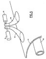
- FIG. 5 schematically represents an assembly of two unidirectional detection units positioned on a shielded cable comprising a central conductor 10 disposed in a envelope 11 filled with a dielectric gas under pressure such as sulfur hexafluoride SF6.
- the two conduits 12 and 13 open out in the envelope 11 and are oriented in opposite directions. They are each connected to a pressure sensor of known type, 14, respectively 15, such as those used for monitoring the density of the dielectric gas.
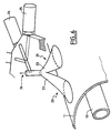
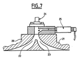
- FIGS. 6 and 7 show another mode of realization of realization of the invention in which there are provided two conduits 20 and 21 of opposite directions including the points 22 and 23 are connected together and connected to two sensors 24 and 25 arranged in parallel. As in the embodiment of the Figure 5, these two sensors are those already installed on envelope 11 to monitor the density of the dielectric gas and sees at 26 a filling valve making it possible to compensate for the density losses detected.
- the value of the pressure measurement time is function of the speed of propagation of pressure waves in the dielectric gas; so in the case of an SF6-nitrogen mixture, this duration will be shorter because the propagation speed is higher than in SF6.
Landscapes
- Physics & Mathematics (AREA)
- General Physics & Mathematics (AREA)
- Acoustics & Sound (AREA)
- Measuring Fluid Pressure (AREA)
- Locating Faults (AREA)
- Testing Relating To Insulation (AREA)
- Gas-Insulated Switchgears (AREA)
- Installation Of Bus-Bars (AREA)
- Examining Or Testing Airtightness (AREA)
Claims (9)
- Verfahren zum Erfassen eines internen Lichtbogens in einer elektrischen Verbindung unter einer metallischen Hülle (11), bei dem an einem festen Ort der Hülle (11) die ansteigende Flanke (5) der von dem Lichtbogen erzeugten und sich in der Hülle (11) ausbreitenden Überdruckwelle erfasst wird, dadurch gekennzeichnet, dass ständig während zweier Zeitspannen, die kürzer als die Durchgangszeit der ansteigenden Flanke (5) sind und durch ein Zeitintervall getrennt sind, das kürzer als die Durchgangszeit der ansteigenden Flanke (5) ist, der Druck in der Hülle gemessen wird, dass die Kurve über die Zeit während dieser zwei Zeitspannen integriert wird, dass die Differenz (Δ) zwischen den zwei Integrationswerten bestimmt wird, und dass die erhaltene Druckdifferenz (Δ) mit einem Schwellwert (ΔP) verglichen wird.
- Verfahren nach Anspruch 1, dadurch gekennzeichnet, dass die Messzeitspannen im wesentlichen gleich der halben Durchgangszeit der ansteigenden Flanke (5) sind.
- Verfahren nach Anspruch 2, dadurch gekennzeichnet, dass das Zeitintervall im wesentlichen gleich der Hälfte der Durchgangszeit der ansteigenden Flanke (5) ist.
- Verfahren nach Anspruch 1, dadurch gekennzeichnet, dass die Erfassung im wesentlichen in der Mitte des zu überwachenden Stücks der Hülle erfolgt.
- Vorrichtung zur Durchführung des Verfahrens nach einem der Ansprüche 1 bis 4, dadurch gekennzeichnet, dass sie wenigstens eine unidirektionale Erfassungseinheit umfasst, die durch einen Druckmessaufnehmer (4, 4>, 14, 15, 24, 25) gebildet ist, der außerhalb der Hülle (11) angeordnet und mit dem Inneren der Hülle (11) über eine hornförmige Leitung (7, 7>, 12, 13, 20, 21) verbunden ist, die in Bezug auf die Achse der Hülle (11) geneigt ist, deren Mündung in die Hülle mündet und deren Spitze (22, 23) mit dem Druckaufnehmer (4, 4>, 14, 15, 24, 25) verbunden ist.
- Vorrichtung nach Anspruch 5, dadurch gekennzeichnet, dass sie eine Anordnung von wengistens zwei unidirektionalen Erfassungseinheiten mit gleicher Erfassungsrichtung umfasst, die zueinander benachbart angeordnet sind und deren Leitungen im gleichen Sinne geneigt sind.
- Vorrichtung nach Anspruch 6, dadurch gekennzeichnet, dass sie zwei unidirektionale Erfassungsanordnungen umfasst, deren Leitungen entgegengesetzt geneigt sind und die einander benachbart angeordnet sind.
- Vorrichtung nach Anspruch 5, dadurch gekennzeichnet, dass sie zwei Druckaufnehmer (24, 25) umfasst, die parallel an zwei Leitungen (20, 21) angeschlossen sind, die entgegengesetzt geneigt sind und deren Spitzen (22, 23) miteinander kommunizieren.
- Vorrichtung nach Anspruch 5, dadurch gekennzeichnet, dass sie zwei gerichtete Erfassungseinheiten (4, 7, 4>, 7>; 12, 14; 13, 15) umfasst, deren Leitungen (7, 7>; 14, 15) entgegengesetzt geneigt sind.
Applications Claiming Priority (2)
| Application Number | Priority Date | Filing Date | Title |
|---|---|---|---|
| FR9814819A FR2786274B1 (fr) | 1998-11-25 | 1998-11-25 | Procede et dispositif de detection d'un arc interne dans une liaison electrique sous enveloppe metallique |
| FR9814819 | 1998-11-25 |
Publications (2)
| Publication Number | Publication Date |
|---|---|
| EP1004884A1 EP1004884A1 (de) | 2000-05-31 |
| EP1004884B1 true EP1004884B1 (de) | 2002-07-31 |
Family
ID=9533152
Family Applications (1)
| Application Number | Title | Priority Date | Filing Date |
|---|---|---|---|
| EP99402904A Expired - Lifetime EP1004884B1 (de) | 1998-11-25 | 1999-11-23 | Gerät und Verfahren zur Erfassung von internen Lichtbogenfehlern in einem metallgekapselten Leiter |
Country Status (12)
| Country | Link |
|---|---|
| US (2) | US6481280B1 (de) |
| EP (1) | EP1004884B1 (de) |
| JP (1) | JP2000206173A (de) |
| KR (1) | KR20000035632A (de) |
| CN (1) | CN1145038C (de) |
| BR (1) | BR9905737A (de) |
| CA (1) | CA2290799A1 (de) |
| DE (1) | DE69902338T2 (de) |
| FR (1) | FR2786274B1 (de) |
| IL (1) | IL133048A (de) |
| SG (1) | SG81334A1 (de) |
| TW (1) | TW526336B (de) |
Families Citing this family (4)
| Publication number | Priority date | Publication date | Assignee | Title |
|---|---|---|---|---|
| FR2786274B1 (fr) * | 1998-11-25 | 2000-12-29 | Alstom Technology | Procede et dispositif de detection d'un arc interne dans une liaison electrique sous enveloppe metallique |
| WO2003044546A1 (de) * | 2001-11-19 | 2003-05-30 | Alstom Technology Ltd | Verfahren zum detektieren eines in einer elektrischen einrichtung in der nähe eines neutralen punktes auftretenden erdschlusses sowie vorrichtung zur durchführung des verfahrens |
| JP2006151159A (ja) * | 2004-11-29 | 2006-06-15 | Shimano Inc | 自転車用クランクの固定構造 |
| RU2670189C1 (ru) * | 2017-08-31 | 2018-10-18 | Юрий Анатольевич Калинчук | Устройство контроля высоковольтного оборудования, находящегося под напряжением |
Family Cites Families (10)
| Publication number | Priority date | Publication date | Assignee | Title |
|---|---|---|---|---|
| US4158168A (en) * | 1977-12-06 | 1979-06-12 | Westinghouse Electric Corp. | Acoustic waveguides for sensing and locating corona discharges |
| KR820001828B1 (ko) * | 1977-12-06 | 1982-10-12 | 에이. 엠. 케네디 2세 | 전기장치내의 코로나 방전의 감지 및 위치 측정장치 |
| USH536H (en) * | 1986-07-18 | 1988-10-04 | The United States Of America As Represented By The Secretary Of The Army | Method of detecting and locating an electrostatic discharge event |
| JPS63210676A (ja) * | 1987-02-26 | 1988-09-01 | Kansai Electric Power Co Inc:The | ガス絶縁開閉装置のための事故点標定装置 |
| US4790190A (en) * | 1987-10-02 | 1988-12-13 | Servo Corporation Of America | On-line acoustic detection of bearing defects |
| US4957007A (en) * | 1988-04-28 | 1990-09-18 | Westinghouse Electric Corp. | Bi-directional pressure sensing probe |
| US5446788A (en) * | 1992-09-29 | 1995-08-29 | Unex Corporation | Adjustable telephone headset |
| SE515388C2 (sv) * | 1995-09-14 | 2001-07-23 | Abb Research Ltd | Anordning för avkänning av elektriska urladdningar i ett provobjekt |
| FR2757321B1 (fr) * | 1996-12-16 | 1999-01-15 | Gec Alsthom T & D Sa | Procede de discrimination entre un arc interne et un arc de coupure detectes dans une installation electrique sous enveloppe metallique |
| FR2786274B1 (fr) * | 1998-11-25 | 2000-12-29 | Alstom Technology | Procede et dispositif de detection d'un arc interne dans une liaison electrique sous enveloppe metallique |
-
1998
- 1998-11-25 FR FR9814819A patent/FR2786274B1/fr not_active Expired - Fee Related
-
1999
- 1999-11-19 IL IL13304899A patent/IL133048A/xx active IP Right Grant
- 1999-11-23 CA CA002290799A patent/CA2290799A1/fr not_active Abandoned
- 1999-11-23 SG SG9905868A patent/SG81334A1/en unknown
- 1999-11-23 US US09/447,058 patent/US6481280B1/en not_active Expired - Fee Related
- 1999-11-23 DE DE69902338T patent/DE69902338T2/de not_active Expired - Fee Related
- 1999-11-23 EP EP99402904A patent/EP1004884B1/de not_active Expired - Lifetime
- 1999-11-24 BR BR9905737-9A patent/BR9905737A/pt not_active IP Right Cessation
- 1999-11-24 JP JP11332282A patent/JP2000206173A/ja active Pending
- 1999-11-24 KR KR1019990052322A patent/KR20000035632A/ko not_active Withdrawn
- 1999-11-25 CN CNB991248848A patent/CN1145038C/zh not_active Expired - Fee Related
- 1999-12-04 TW TW088120619A patent/TW526336B/zh not_active IP Right Cessation
-
2002
- 2002-07-01 US US10/185,065 patent/US6581462B2/en not_active Expired - Fee Related
Also Published As
| Publication number | Publication date |
|---|---|
| IL133048A (en) | 2003-07-06 |
| US6481280B1 (en) | 2002-11-19 |
| JP2000206173A (ja) | 2000-07-28 |
| KR20000035632A (ko) | 2000-06-26 |
| EP1004884A1 (de) | 2000-05-31 |
| US20020166397A1 (en) | 2002-11-14 |
| IL133048A0 (en) | 2001-03-19 |
| BR9905737A (pt) | 2001-10-30 |
| SG81334A1 (en) | 2001-06-19 |
| TW526336B (en) | 2003-04-01 |
| FR2786274B1 (fr) | 2000-12-29 |
| CA2290799A1 (fr) | 2000-05-25 |
| US6581462B2 (en) | 2003-06-24 |
| FR2786274A1 (fr) | 2000-05-26 |
| CN1260495A (zh) | 2000-07-19 |
| DE69902338D1 (de) | 2002-09-05 |
| CN1145038C (zh) | 2004-04-07 |
| DE69902338T2 (de) | 2003-03-13 |
Similar Documents
| Publication | Publication Date | Title |
|---|---|---|
| FR2723170A1 (fr) | Detecteur et procede de detection de defauts pour des tuyaux en metal | |
| EP3411668B1 (de) | Verfahren zur überwachung des thermomechanischen verhaltens einer tiefseeleitung zum transport von unter hohem druck stehenden flüssigkeiten | |
| CA2399615A1 (fr) | Procede et dispositif non intrusif pour caracteriser les perturbations d'ecoulement d'un fluide a l'interieur d'une canalisation | |
| FR2675579A1 (fr) | Detecteur de defauts pour un materiau metallique, notamment une canalisation, et capteur de courants de foucault a champ distant destine a ce detecteur. | |
| EP3227651B2 (de) | Verfahren und vorrichtung zur feststellung von kritischen punkten in einer anlage, insbesondere zum erkennen von lecks in luftkanälen | |
| EP0746747A1 (de) | Verfahren und vorrichtung zum messen, während übergangszustände, der temperatur und des wärmeflusses durch oberflächen | |
| EP1064533B1 (de) | Vorrichtung und verfahren zur unmittelbaren messung des heizwertes eines brennbaren gases | |
| EP1004884B1 (de) | Gerät und Verfahren zur Erfassung von internen Lichtbogenfehlern in einem metallgekapselten Leiter | |
| EP0455562B1 (de) | Anordnung zur Feststellung interner Funkenüberschläge in einer abgeschirmten elektrischen Installation | |
| EP2938512A2 (de) | Erkennung von defekten in einem sammlungsstreifen | |
| EP1277034A1 (de) | Verfahren und installation zur aufspürung und ortsbestimmung einer geräusch- und vibrationsquelle | |
| FR2582806A1 (fr) | Dispositif a utiliser dans les microphones a pression afin d'ameliorer leurs proprietes a basse frequence | |
| CA2823172A1 (fr) | Dispositif et procede de surveillance de rotor | |
| FR2498325A1 (fr) | Dispositif pour localiser les fuites dans une tuyauterie de refoulement | |
| EP1250607B1 (de) | Verfahren und vorrichtung zur überwachung eines telekommunikationskabels | |
| WO1992018835A1 (fr) | Detecteur a ultrasons, procede de detection pour milieux liquides et procede de controle d'un emetteur d'ultrasons | |
| EP0100694A1 (de) | Isoliertes Kabel für den Transport elektrischer Energie insbesondere hoher Spannung und Vorrichtung zum Erkennen von Fehlern in einem solchen Kabel | |
| FR2754631A1 (fr) | Dispositif de surveillance pour un cable a isolation gazeuse | |
| EP1014522B1 (de) | Verfahren zur Messung der Dichte eines dielektrischen Gases in einer erdverlegten gekapselten Leitung | |
| FR2974910A1 (fr) | Dispositif et une methode de detection et de localisation d'un defaut sur un cable electrique coaxial a isolation gazeuse | |
| EP0148690A1 (de) | Einrichtung zum Nachweisen von Partikeln, insbesondere festen Partikeln in einem gasförmigen Fluid, das aus einer Leitung herausfliesst | |
| EP4551953A1 (de) | Vorrichtung zur akustischen erfassung eines lichtbogens | |
| EP0228972B1 (de) | Vorrichtung und Verfahren zur Kontrolle des Füllstandes von Pulver in einem Behälter | |
| FR3022652A1 (fr) | Procede de detection de defaillance dans un dispositif de regulation et dispositif de regulation correspondant | |
| FR2487115A1 (fr) | Dispositif de signalisation d'elevation de temperature dans un systeme de transmission haute-frequence de puissance |
Legal Events
| Date | Code | Title | Description |
|---|---|---|---|
| PUAI | Public reference made under article 153(3) epc to a published international application that has entered the european phase |
Free format text: ORIGINAL CODE: 0009012 |
|
| AK | Designated contracting states |
Kind code of ref document: A1 Designated state(s): CH DE FR GB LI |
|
| AX | Request for extension of the european patent |
Free format text: AL;LT;LV;MK;RO;SI |
|
| 17P | Request for examination filed |
Effective date: 20001130 |
|
| AKX | Designation fees paid |
Free format text: CH DE FR GB LI |
|
| 17Q | First examination report despatched |
Effective date: 20010219 |
|
| GRAG | Despatch of communication of intention to grant |
Free format text: ORIGINAL CODE: EPIDOS AGRA |
|
| GRAG | Despatch of communication of intention to grant |
Free format text: ORIGINAL CODE: EPIDOS AGRA |
|
| GRAH | Despatch of communication of intention to grant a patent |
Free format text: ORIGINAL CODE: EPIDOS IGRA |
|
| GRAH | Despatch of communication of intention to grant a patent |
Free format text: ORIGINAL CODE: EPIDOS IGRA |
|
| GRAA | (expected) grant |
Free format text: ORIGINAL CODE: 0009210 |
|
| AK | Designated contracting states |
Kind code of ref document: B1 Designated state(s): CH DE FR GB LI |
|
| REG | Reference to a national code |
Ref country code: GB Ref legal event code: FG4D Free format text: NOT ENGLISH Ref country code: CH Ref legal event code: EP |
|
| REG | Reference to a national code |
Ref country code: CH Ref legal event code: NV Representative=s name: CABINET ROLAND NITHARDT CONSEILS EN PROPRIETE INDU |
|
| REF | Corresponds to: |
Ref document number: 69902338 Country of ref document: DE Date of ref document: 20020905 |
|
| GBT | Gb: translation of ep patent filed (gb section 77(6)(a)/1977) |
Effective date: 20020829 |
|
| PLBE | No opposition filed within time limit |
Free format text: ORIGINAL CODE: 0009261 |
|
| STAA | Information on the status of an ep patent application or granted ep patent |
Free format text: STATUS: NO OPPOSITION FILED WITHIN TIME LIMIT |
|
| 26N | No opposition filed |
Effective date: 20030506 |
|
| PGFP | Annual fee paid to national office [announced via postgrant information from national office to epo] |
Ref country code: GB Payment date: 20041117 Year of fee payment: 6 |
|
| PGFP | Annual fee paid to national office [announced via postgrant information from national office to epo] |
Ref country code: FR Payment date: 20041126 Year of fee payment: 6 |
|
| PGFP | Annual fee paid to national office [announced via postgrant information from national office to epo] |
Ref country code: CH Payment date: 20041129 Year of fee payment: 6 |
|
| PGFP | Annual fee paid to national office [announced via postgrant information from national office to epo] |
Ref country code: DE Payment date: 20041201 Year of fee payment: 6 |
|
| PG25 | Lapsed in a contracting state [announced via postgrant information from national office to epo] |
Ref country code: GB Free format text: LAPSE BECAUSE OF NON-PAYMENT OF DUE FEES Effective date: 20051123 |
|
| PG25 | Lapsed in a contracting state [announced via postgrant information from national office to epo] |
Ref country code: LI Free format text: LAPSE BECAUSE OF NON-PAYMENT OF DUE FEES Effective date: 20051130 Ref country code: CH Free format text: LAPSE BECAUSE OF NON-PAYMENT OF DUE FEES Effective date: 20051130 |
|
| PG25 | Lapsed in a contracting state [announced via postgrant information from national office to epo] |
Ref country code: DE Free format text: LAPSE BECAUSE OF NON-PAYMENT OF DUE FEES Effective date: 20060601 |
|
| REG | Reference to a national code |
Ref country code: CH Ref legal event code: PL |
|
| GBPC | Gb: european patent ceased through non-payment of renewal fee |
Effective date: 20051123 |
|
| PG25 | Lapsed in a contracting state [announced via postgrant information from national office to epo] |
Ref country code: FR Free format text: LAPSE BECAUSE OF NON-PAYMENT OF DUE FEES Effective date: 20060731 |
|
| REG | Reference to a national code |
Ref country code: FR Ref legal event code: ST Effective date: 20060731 |