EP1004898B1 - Träger mit zwei Ringen für eine Gammakamera - Google Patents
Träger mit zwei Ringen für eine Gammakamera Download PDFInfo
- Publication number
- EP1004898B1 EP1004898B1 EP99402936A EP99402936A EP1004898B1 EP 1004898 B1 EP1004898 B1 EP 1004898B1 EP 99402936 A EP99402936 A EP 99402936A EP 99402936 A EP99402936 A EP 99402936A EP 1004898 B1 EP1004898 B1 EP 1004898B1
- Authority
- EP
- European Patent Office
- Prior art keywords
- detector
- gamma camera
- camera according
- foot
- rail
- Prior art date
- Legal status (The legal status is an assumption and is not a legal conclusion. Google has not performed a legal analysis and makes no representation as to the accuracy of the status listed.)
- Expired - Lifetime
Links
- 230000001360 synchronised effect Effects 0.000 claims 1
- 238000006073 displacement reaction Methods 0.000 description 16
- 238000003325 tomography Methods 0.000 description 10
- 238000013519 translation Methods 0.000 description 8
- 230000014616 translation Effects 0.000 description 8
- 210000000056 organ Anatomy 0.000 description 4
- 230000009467 reduction Effects 0.000 description 3
- 230000002441 reversible effect Effects 0.000 description 3
- 238000002603 single-photon emission computed tomography Methods 0.000 description 3
- 241001272720 Medialuna californiensis Species 0.000 description 2
- 238000013459 approach Methods 0.000 description 2
- 230000008901 benefit Effects 0.000 description 2
- 238000013461 design Methods 0.000 description 2
- 230000000694 effects Effects 0.000 description 2
- 230000005251 gamma ray Effects 0.000 description 2
- 238000004519 manufacturing process Methods 0.000 description 2
- 238000000034 method Methods 0.000 description 2
- BASFCYQUMIYNBI-UHFFFAOYSA-N platinum Chemical compound [Pt] BASFCYQUMIYNBI-UHFFFAOYSA-N 0.000 description 2
- 229920000297 Rayon Polymers 0.000 description 1
- 240000008042 Zea mays Species 0.000 description 1
- 230000001154 acute effect Effects 0.000 description 1
- 238000002583 angiography Methods 0.000 description 1
- 230000000712 assembly Effects 0.000 description 1
- 238000000429 assembly Methods 0.000 description 1
- 238000005452 bending Methods 0.000 description 1
- 238000013155 cardiography Methods 0.000 description 1
- 239000003638 chemical reducing agent Substances 0.000 description 1
- 238000002591 computed tomography Methods 0.000 description 1
- 238000001514 detection method Methods 0.000 description 1
- 238000005516 engineering process Methods 0.000 description 1
- 238000009434 installation Methods 0.000 description 1
- 239000003550 marker Substances 0.000 description 1
- 230000002503 metabolic effect Effects 0.000 description 1
- 230000004060 metabolic process Effects 0.000 description 1
- 238000009206 nuclear medicine Methods 0.000 description 1
- 230000008520 organization Effects 0.000 description 1
- 229910052697 platinum Inorganic materials 0.000 description 1
- 230000008569 process Effects 0.000 description 1
- 230000000135 prohibitive effect Effects 0.000 description 1
- 239000002964 rayon Substances 0.000 description 1
- 238000012552 review Methods 0.000 description 1
- 238000000926 separation method Methods 0.000 description 1
- 239000002689 soil Substances 0.000 description 1
- 239000007787 solid Substances 0.000 description 1
- 229910052713 technetium Inorganic materials 0.000 description 1
- GKLVYJBZJHMRIY-UHFFFAOYSA-N technetium atom Chemical compound [Tc] GKLVYJBZJHMRIY-UHFFFAOYSA-N 0.000 description 1
- 229910052716 thallium Inorganic materials 0.000 description 1
- BKVIYDNLLOSFOA-UHFFFAOYSA-N thallium Chemical compound [Tl] BKVIYDNLLOSFOA-UHFFFAOYSA-N 0.000 description 1
- 238000012549 training Methods 0.000 description 1
Images


Classifications
-
- G—PHYSICS
- G01—MEASURING; TESTING
- G01T—MEASUREMENT OF NUCLEAR OR X-RADIATION
- G01T1/00—Measuring X-radiation, gamma radiation, corpuscular radiation, or cosmic radiation
- G01T1/16—Measuring radiation intensity
- G01T1/161—Applications in the field of nuclear medicine, e.g. in vivo counting
- G01T1/164—Scintigraphy
- G01T1/1641—Static instruments for imaging the distribution of radioactivity in one or two dimensions using one or several scintillating elements; Radio-isotope cameras
- G01T1/1642—Static instruments for imaging the distribution of radioactivity in one or two dimensions using one or several scintillating elements; Radio-isotope cameras using a scintillation crystal and position sensing photodetector arrays, e.g. ANGER cameras
-
- G—PHYSICS
- G01—MEASURING; TESTING
- G01T—MEASUREMENT OF NUCLEAR OR X-RADIATION
- G01T1/00—Measuring X-radiation, gamma radiation, corpuscular radiation, or cosmic radiation
- G01T1/16—Measuring radiation intensity
- G01T1/161—Applications in the field of nuclear medicine, e.g. in vivo counting
- G01T1/164—Scintigraphy
- G01T1/1641—Static instruments for imaging the distribution of radioactivity in one or two dimensions using one or several scintillating elements; Radio-isotope cameras
- G01T1/1648—Ancillary equipment for scintillation cameras, e.g. reference markers, devices for removing motion artifacts, calibration devices
Definitions
- the present invention relates to a gamma camera with two tunnel type crowns for universal use.
- the object of the invention is to to make the design of such a gamma camera more rational so that it can be used for multiple purposes.
- PET or SPECT Pulsiton Emission Tomography, coincidence emission tomography, Single Photon Emission Computed Tomography, tomography constructed from emissions from individual photons.
- PET or SPECT Pulsiton Emission Tomography, coincidence emission tomography, Single Photon Emission Computed Tomography, tomography constructed from emissions from individual photons.
- SPECT Pulsiton Emission Tomography, coincidence emission tomography, Single Photon Emission Computed Tomography, tomography constructed from emissions from individual photons.
- the invention also applies both of these two techniques.
- a radiological marker for example most generally Technetium, sometimes Thallium, or others markers.
- these markers will preferentially fix in certain organs of the patient's body. Through the density of this fixation, they then reveal the functional state of the organ in which they settle. These markers emit during their gamma ray metabolism. These gamma rays are detected by a detector.
- Such a detector comprises on a front face a collimator whose role is to ensure the acquisition of a projected image. It is however known to have collimators with inclined holes or focused holes. The gamma rays which pass through the collimator then end up in a scintillator whose role is to transform each gamma ray into a luminous scintillation. This light scintillation is detectable by a set of photomultiplier tubes arranged downstream of the scintillator. The photomultiplier tubes detect scintillations and deliver correspondence of electrical signals whose amplitude and shape are indicative of the nature and location of the nuclear event detected. We processes these signals, in particular in barycentration matrices, to constitute a revealing image of this nuclear activity.
- the mobility of detectors during these examinations is mechanically very diverse. There are generally seven axes, or seven different engines, at least to be able to access all required positions. Furthermore, the amplitude of certain displacements and the required precision require that mechanical parts used to connect between them different organs of these machines are themselves very robust. This robustness is automatically significant of heaviness and movement limit.
- the invention therefore relates to a gamma camera provided with a stand with two movable rings each supporting a detector by means of a support, characterized in that each support comprises on the one hand and on the other, a sliding rail-shoe system, a first rail-shoe system cooperating with a crown and the other rail-shoe system cooperating with a detector, the two rail-shoe systems providing the detector with sliding in directions perpendicular to each other, a bisector of these directions being collinear to a radius of a crown.
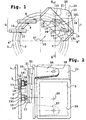
- Figure 1 shows a gamma camera according to the invention.
- Figure 1 is a sectional view, from the front.
- Figure 2 is a side view and section.
- Figure 3 is a front view.
- a stand 1 comprises two crowns 2 and 3.
- the two crowns are coaxial and concentric.
- Crown 2 interior, is inscribed in the crown 3.
- Each crown carries a detector respectively 4 and 5 at by means of a support 6 and 7.
- Figures 1 and 2 show that the support 6 is fixed to the crown 2 by welds 8 to 11.
- Support 7 is fixed to the crown 3 by welds 12 to 15.
- these supports have tube elements oriented like planned displacements of the detectors in translation.
- Figure 1 shows the rail-sliding shoe systems.
- a first system includes a first couple rails 16 and 17, horizontal, on which runners slide 18 and 19 respectively.
- Rail-shoe system means a movable member, a rail, relative to the other, a skate, skates, even a slide.
- the rail can be fixed to a part, for example an intermediate plate 20, then that the pad (s) or the slide are attached to another, for example here the crown 3.
- the pads 18 and 19 are fixed to the crown 3 by means of tube elements 181 and 191 welded by the welds 12 to 15. But the reverse is possible, as long as a piece can slide in translation relative to another.
- the rails and pads provide two functions.
- a first function is a sliding.
- a second function is to maintain in all directions that do not include the sliding direction. In the position shown in Figure 1, the plate 20 can thus move horizontally.
- the plate 20 has two faces.
- On the other side of the plate is installed another system rail-pad comprising in particular two rails 21 and 22.
- the two rails 21 and 22 are made on the other side of the plate 20.
- the rails 21 and 22 are provided to slide in pads 23 and 24 integral with the detector. Both rails 21 and 22, here vertically oriented, are perpendicular to rails 16 and 17.
- the directions of sliding of a detector 5 resulting from the presence of these rails always have a bisector 25 collinear to a radius of the crown 3.
- the radius 25 in question to materialize this bisector is that which passes through the center 37 of crowns 2 and 3, serving as a center of rotation to the whole machine, and through the middle 26 of the detector 5.
- the two detectors 4 and 5 are inclined at 90 ° one by compared to each other.
- the arrangement of the detectors in the machine corresponds in this case to the acquisition of a tomography image.
- the two detectors 4 and 5 touch each other by one of their edges.
- this arrangement is the most profitable and quickest for acquire a reconstructed image.
- we must move together, during rotation, the two detectors in relation to the center of the tunnel. These movements are made possible by coordinated management of sliding, in two perpendicular directions, for each of the detectors that remain contiguous.
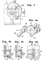
- Figure 4a recalls a design of rotary keys widely used to engage two parts in relative movement.
- a cylindrical part 27 of a key 28 can rotate in a bearing not shown. This bearing belongs to one of the parts to to train, in particular here to train in rotation.
- Key 27 has a hollowed out part 29 in half-moon. This half-moon can be housed, or not, in a recess of the same shape belonging to the other part to be driven.
- the clutch or disengage is obtained by the 180 ° rotation of the key 27.
- an external disc 34 secured to the crown 2 carries the key device.
- the key 28 allows to drive together the two crowns 2 and 3.
- the key 33 in this case allows the two crowns 2 and 3 to rotate together relative to a fixed crown of the stand 1 which supports them.
- the key 33 makes it possible to link the stand 1 to the crown 2 alone.
- the key 28 releases the circular movement of the crown 3. It is possible rather than turning the keys 180 °, by turning them only 90 °, to lock the two crowns together with respect to the stand.
- FIG. 4d shows an engine 35 controlling the gear 31 which itself controls the two gears 30 and 32.
- the systems with rails and runners shown in Figure 1 are of preferably made using three pairs of plates, identical two to of them.
- These pairs AB, CD, and EF of turntables shown respectively on the Figures 5a to 5c all have the particularity of having an outline external 36, rounded with a radius of curvature corresponding to the same radius from the center 37 of the machine.
- the rail-shoe systems of the two detectors are symmetrical from each other with respect to a diametral plane of a gamma-camera tunnel. In one example, this radius of curvature is of the order of 1m.
- the plates A and B, figure 5a are intended to be screwed by multiple screws such as 38 and 39 on crowns 2 and 3 respectively.
- Platinum A carries, opposite to what is described in FIG. 1, the rails 16 and 17 previously mentioned.
- Plate B carries corresponding rails.
- the plate A still carries a motor 40 and a reduction gear 41 which drive a end of an endless screw 42.
- the screw 42 is held at its other end in a bearing 43 also fixed to the plate A.
- the screw 42 is parallel to the rails 16 and 17.
- the plate C comprises, on a visible side, the rails 21 and 22 as well as a geared motor assembly 44-45 which drives a worm 46 held at its other end by a bearing 47.
- the bearing 47 is also fixed on the same face of the plate C.
- the screw 46 is parallel to the rails 21 and 22.
- On another invisible face of the plate C shown in dotted lines are shown pairs of pads 48 and 49 intended for grip on the heads of the rails 16 and 17.
- the plate C still carries in intermediate position between the pads 48 and 49 a nut 50.
- the nut 50 is fixed to plate C. It is engaged in the worm screw 42.
- the gear motor 40-41 drives the screw 42
- the nut 50 welded on the non visible side of plate C requires it to slide through the pads 48 and 49 along rails 16 and 17.
- a third pair of plates E and F has on a visible face stirrups 51 and 52 to support the detectors 5 and 4 respectively. Sure another side, invisible, the plates E and F carry sets of skids 53 and 54 for sliding along the rails 21 and 22. The reverse side of the plates E and F also carries a nut 55 engaged in the worm 46 to be taken by the 44-45 gear motor. With the 44-45 motor reducer thus obtains a vertical elevation (compared to what is shown on the figure) of the detector 5, whereas with the geared motor 40-41 we obtain a lateral translation.
- FIG. 5b shows the preferred dimensions of the deflections along the different translations proposed.
- the rail 21 will have a length 600 mm, the useful travel offered by the worm 46 being around 400 mm. It is the same for the rail 16 and the worm 42 respectively.
- FIG. 2 shows the stirrup 51 with two legs 56 and 57.
- the detector 5 is seen inclined at 45 °, while the left part of FIG. 2 is a view sectional.
- This stirrup 51 carries at the ends of the two legs of the bearings such as 58 which hold the detector 5. In doing so this detector 5 can orient themselves so that an active face 59 of this detector 5 is no longer oriented towards the axis 37 of the machine, but is oriented frontally, on the Figures 1 and 3, facing the observer.
- Detector 5 is not preferably not square but rectangular, it has a large dimension and a small dimension.
- the axis of rotation passing through the bearing 58 is parallel to the large dimension of the detector 5. In this use the detector will be vertical.
- the axis of rotation which passes by the bearings of the stirrups is always inclined with respect to the translations 16, 17,21 and 22.
- Figure 6 shows a use where the two detectors 4 and 5 are inclined relative to each other by 75 °. This is achieved by orienting the crowns 2 and 3 relative to each other, so that their indexes initials make a deviation of 75 °. Once this position is reached, it suffices, by example with the plates A, C, E of the detector 5 to move it along the rails 16 and 17 and 21 and 22 so that it approaches detector 4. that even in this position the displacements 60 are substantially collinear to the directions of rails 16 and 17. These directions 60 of displacement make the best use of the orientations of rails 16 and 17. To obtain a displacement 60 with sliding of the radial type and tangential, the displacements would have been approximately ⁇ 2 greater.
- Figure 7 shows a particularly interesting example of using a gamma-camera according to the invention.
- a transporter plate 63 which carries the body 61 can pass from one platform 62 to another 64.
- the advantage of using a such a solution is located in a free clearance 65 existing under the patient, and allowing in particular to pass detectors 4 and 5 therein during the exam. It will be noted that this clearance 65 is obtained without having to overly strengthen the ferry platform 63, or have to suffer effects contrariants of its bending in case the overhang of this plate 62 is important.
- the tray will almost always be carried by the two docks 62 and 64.
- the deflections that it undergoes are then negligible and their consequences in the images are not perceptible.
- a platform 62 will have a significant elevation possibility. For example there may rise from 600 mm to 1100 mm above the ground. The low position allows easier placement of certain patients with reduced mobility. On the other side of the machine, platform 64 will not require travel also important in height. Travel from 850 to 1100 mm may be sufficient to take into account the useful space in tunnel 66 of the machine.
- the only synchronization that should be implemented in the elevation of platforms 62 and 63 is the one by which, when platform 62 entered the adjustment phase from 850 to 1100 mm, platform 64 copies its position in altitude.
- platforms 62 and 64 make travel unusable side. This is not a problem in the invention since with the chosen solution there is no longer any need to move the stand laterally 1 in relation to the patient's bed, constituted by platforms 62 and 64 and by the transporter 63.
- FIG. 7 also recalls in section the assemblies of the plates A, B, C, D, E and F in the stand 1. It is also integral with a frame 67 which rests on the ground by means of two longitudinal beams 68 longitudinal in bed 62-64.
Landscapes
- Physics & Mathematics (AREA)
- Health & Medical Sciences (AREA)
- Life Sciences & Earth Sciences (AREA)
- General Physics & Mathematics (AREA)
- General Health & Medical Sciences (AREA)
- Medical Informatics (AREA)
- Nuclear Medicine, Radiotherapy & Molecular Imaging (AREA)
- Optics & Photonics (AREA)
- Engineering & Computer Science (AREA)
- Biomedical Technology (AREA)
- High Energy & Nuclear Physics (AREA)
- Molecular Biology (AREA)
- Spectroscopy & Molecular Physics (AREA)
- Nuclear Medicine (AREA)
- Measurement Of Radiation (AREA)
- Picture Signal Circuits (AREA)
- Processing Of Color Television Signals (AREA)
Claims (8)
- Gammastrahlen-Kamera mit einem Stativ (1) mit zwei beweglichen Ringen (2, 3), die je einen Detektor (4, 5) mittels eines Trägers (20) halten, dadurch gekennzeichnet, daß jeder Träger zu beiden Seiten ein Schiene-Schlitten-System zur Gleitbewegung aufweist, wobei ein erstes Schiene-Schlitten-System (16-19) mit dem Ring und das andere Schienen-Schlitten-System (21,24) mit einem Detektor zusammenwirkt, wobei die beiden Schiene-Schlitten-Systeme dem Detektor Gleitbewegungen in zueinander senkrechten Richtungen ermöglichen, wobei eine Winkelhalbierende (25) dieser Richtungen zum Radius eines Rings kollinear ist.
- Gammastrahlen-Kamera nach Anspruch 1, dadurch gekennzeichnet, daß die beiden Ringe koaxial, vorzugsweise konzentrisch sind.
- Gammastrahlen-Kamera nach einem der Ansprüche 1 bis 2, dadurch gekennzeichnet, daß das Stativ (1) ortsfest ist.
- Gammastrahlen-Kamera nach einem der Ansprüche 1 bis 3, dadurch gekennzeichnet, daß das Stativ einen ortsfesten Ring aufweist, der die beiden beweglichen Ringe trägt.
- Gammastrahlen-Kamera nach einem der Ansprüche 1 bis 4, dadurch gekennzeichnet, daß ein an einem Ring befestigtes Schiene-Schlitten-System einen Bügel (52) mit zwei Schenkeln (56, 57) aufweist, wobei ein Lager (58) für den Halt des Detektors drehbar am Ende dieser beiden Schenkel angeordnet ist, wobei die Achse dieses Lagers vorzugsweise gemäß einer großen Abmessung eines Detektors ausgerichtet ist.
- Gammastrahlen-Kamera nach einem der Ansprüche I bis 5, dadurch gekennzeichnet, daß die Schiene-Schlitten-Systeme der beiden Detektoren zueinander in bezug auf eine diametrale Ebene eines Tunnels der Gammastrahlen-Kamera symmetrisch sind.
- Gammastrahlen-Kamera nach einem der Ansprüche 1 bis 6, dadurch gekennzeichnet, daß sie ein Bett mit zwei Rampen (62, 64) und einer Wandertisch-Platte (63) von einer Rampe zur anderen aufweist.
- Gammastrahlen-Kamera nach Anspruch 7, dadurch gekennzeichnet, daß die Rampen variable Höhen aufweisen, wobei die Höheneinstellungen der Rampen in einem hohen Bereich der Variation dieser Höhen synchronisiert sind.
Applications Claiming Priority (2)
| Application Number | Priority Date | Filing Date | Title |
|---|---|---|---|
| FR9814999 | 1998-11-27 | ||
| FR9814999A FR2786570B1 (fr) | 1998-11-27 | 1998-11-27 | Gamma-camera avec deux couronnes |
Publications (2)
| Publication Number | Publication Date |
|---|---|
| EP1004898A1 EP1004898A1 (de) | 2000-05-31 |
| EP1004898B1 true EP1004898B1 (de) | 2001-06-13 |
Family
ID=9533302
Family Applications (1)
| Application Number | Title | Priority Date | Filing Date |
|---|---|---|---|
| EP99402936A Expired - Lifetime EP1004898B1 (de) | 1998-11-27 | 1999-11-25 | Träger mit zwei Ringen für eine Gammakamera |
Country Status (7)
| Country | Link |
|---|---|
| EP (1) | EP1004898B1 (de) |
| AT (1) | ATE202214T1 (de) |
| CA (1) | CA2290865A1 (de) |
| DE (1) | DE69900152T2 (de) |
| DK (1) | DK1004898T3 (de) |
| ES (1) | ES2158729T3 (de) |
| FR (1) | FR2786570B1 (de) |
Families Citing this family (2)
| Publication number | Priority date | Publication date | Assignee | Title |
|---|---|---|---|---|
| FR2841456B1 (fr) * | 2002-06-26 | 2005-06-03 | Sopha Medical Vision Internat | Machine de medecine nucleaire a lit en porte-a-feu et son utilisation |
| JP4929448B2 (ja) * | 2005-07-29 | 2012-05-09 | 財団法人ヒューマンサイエンス振興財団 | 断層撮影装置 |
Family Cites Families (3)
| Publication number | Priority date | Publication date | Assignee | Title |
|---|---|---|---|---|
| US4928283A (en) * | 1988-02-26 | 1990-05-22 | Analogic Corporation | X-ray tomography apparatus |
| FR2677458B1 (fr) * | 1991-06-07 | 1993-09-03 | Sopha Medical | Procede d'acquisition tomographique, a deux detecteurs, a centyre de visee distinct du centre de rotation. |
| US5523571A (en) * | 1995-03-31 | 1996-06-04 | Siemens Medical Systems, Inc. | Versatile reconfigurable gantry for use in scintillation camera systems |
-
1998
- 1998-11-27 FR FR9814999A patent/FR2786570B1/fr not_active Expired - Fee Related
-
1999
- 1999-11-25 DE DE69900152T patent/DE69900152T2/de not_active Expired - Fee Related
- 1999-11-25 ES ES99402936T patent/ES2158729T3/es not_active Expired - Lifetime
- 1999-11-25 AT AT99402936T patent/ATE202214T1/de not_active IP Right Cessation
- 1999-11-25 EP EP99402936A patent/EP1004898B1/de not_active Expired - Lifetime
- 1999-11-25 DK DK99402936T patent/DK1004898T3/da active
- 1999-11-26 CA CA002290865A patent/CA2290865A1/fr not_active Abandoned
Also Published As
| Publication number | Publication date |
|---|---|
| FR2786570A1 (fr) | 2000-06-02 |
| CA2290865A1 (fr) | 2000-05-27 |
| ES2158729T3 (es) | 2001-09-01 |
| EP1004898A1 (de) | 2000-05-31 |
| DK1004898T3 (da) | 2001-09-03 |
| FR2786570B1 (fr) | 2001-01-12 |
| DE69900152D1 (de) | 2001-07-19 |
| DE69900152T2 (de) | 2001-10-31 |
| ATE202214T1 (de) | 2001-06-15 |
Similar Documents
| Publication | Publication Date | Title |
|---|---|---|
| EP0069607B1 (de) | Lastträgerführungsstück mit teleskopischem Aufbau und damit verschene Roentgenanlage | |
| WO2007119459A1 (ja) | マンモグラフィ装置 | |
| EP1246565A1 (de) | Auswertungseinrichtung des gleichgewichtstandes des menschlichen körpers | |
| US10966672B2 (en) | Sliding arrangement for mobile tomosynthesis X-ray system | |
| FR2601579A1 (fr) | Lit d'examen, notamment pour appareil de rmn ou de tomodensitometrie. | |
| CN113143304B (zh) | 一种具备3d成像功能的dr装置 | |
| EP1004898B1 (de) | Träger mit zwei Ringen für eine Gammakamera | |
| FR2786387A1 (fr) | Dispositif et procede de prise d'images radiologiques | |
| EP0426568B1 (de) | Gamma-Kameraeinrichtung mit zwei Detektorköpfen | |
| EP1004897B1 (de) | Konvertierbare Gammakamera | |
| EP0730432B1 (de) | Medizinische abbildungsvorrichtung für allgemeine und/oder kardiovaskuläre röntgenuntersuchungen mit diagnostischen oder therapeutischen einstellungen | |
| FR2809849A1 (fr) | Procede et dispositif d'acquisition d'images | |
| EP0376807B1 (de) | Patientenliegetisch für Untersuchungen auf Szintigraphieanordnungen | |
| JP2003190137A (ja) | 被検体の断層撮影方法及び装置 | |
| JP4409865B2 (ja) | 核医学診断装置 | |
| FR2821263A1 (fr) | Appareil de radiodiagnostic telecommande universel | |
| FR2752947A1 (fr) | Machine de medecine nucleaire | |
| JPH0612555Y2 (ja) | シンチレ−シヨンカメラ | |
| FR2601580A1 (fr) | Lit medical d'examen, notamment pour appareil de rmn ou de tomodensitometrie. | |
| FR2841457A1 (fr) | Machine de medecine nucleaire compacte et son utlisation | |
| FR2518400A1 (fr) | Table orthopedique comportant des supports mobiles pour la partie superieure du corps et le sacrum | |
| CN1150536A (zh) | 计算机层析x射线摄影装置 | |
| WO2004003588A1 (fr) | Machine de medecine nucleaire notamment a correction d'absorption | |
| FR2640868A1 (de) | ||
| FR2616650A1 (fr) | Dispositif de radiologie de campagne |
Legal Events
| Date | Code | Title | Description |
|---|---|---|---|
| PUAI | Public reference made under article 153(3) epc to a published international application that has entered the european phase |
Free format text: ORIGINAL CODE: 0009012 |
|
| AK | Designated contracting states |
Kind code of ref document: A1 Designated state(s): AT BE CH CY DE DK ES FI FR GB GR IE IT LI LU MC NL PT SE |
|
| AX | Request for extension of the european patent |
Free format text: AL;LT;LV;MK;RO;SI |
|
| RAP1 | Party data changed (applicant data changed or rights of an application transferred) |
Owner name: SOPHA MEDICAL VISION INTERNATIONAL |
|
| 17P | Request for examination filed |
Effective date: 20000509 |
|
| GRAG | Despatch of communication of intention to grant |
Free format text: ORIGINAL CODE: EPIDOS AGRA |
|
| 17Q | First examination report despatched |
Effective date: 20000918 |
|
| GRAG | Despatch of communication of intention to grant |
Free format text: ORIGINAL CODE: EPIDOS AGRA |
|
| GRAH | Despatch of communication of intention to grant a patent |
Free format text: ORIGINAL CODE: EPIDOS IGRA |
|
| GRAH | Despatch of communication of intention to grant a patent |
Free format text: ORIGINAL CODE: EPIDOS IGRA |
|
| AKX | Designation fees paid |
Free format text: AT BE CH CY DE DK ES FI FR GB GR IE IT LI LU MC NL PT SE |
|
| GRAA | (expected) grant |
Free format text: ORIGINAL CODE: 0009210 |
|
| AK | Designated contracting states |
Kind code of ref document: B1 Designated state(s): AT BE CH CY DE DK ES FI FR GB GR IE IT LI LU MC NL PT SE |
|
| PG25 | Lapsed in a contracting state [announced via postgrant information from national office to epo] |
Ref country code: NL Free format text: LAPSE BECAUSE OF FAILURE TO SUBMIT A TRANSLATION OF THE DESCRIPTION OR TO PAY THE FEE WITHIN THE PRESCRIBED TIME-LIMIT Effective date: 20010613 Ref country code: IE Free format text: LAPSE BECAUSE OF FAILURE TO SUBMIT A TRANSLATION OF THE DESCRIPTION OR TO PAY THE FEE WITHIN THE PRESCRIBED TIME-LIMIT Effective date: 20010613 Ref country code: FI Free format text: LAPSE BECAUSE OF FAILURE TO SUBMIT A TRANSLATION OF THE DESCRIPTION OR TO PAY THE FEE WITHIN THE PRESCRIBED TIME-LIMIT Effective date: 20010613 Ref country code: CY Free format text: LAPSE BECAUSE OF NON-PAYMENT OF DUE FEES Effective date: 20010613 Ref country code: AT Free format text: LAPSE BECAUSE OF FAILURE TO SUBMIT A TRANSLATION OF THE DESCRIPTION OR TO PAY THE FEE WITHIN THE PRESCRIBED TIME-LIMIT Effective date: 20010613 |
|
| REF | Corresponds to: |
Ref document number: 202214 Country of ref document: AT Date of ref document: 20010615 Kind code of ref document: T |
|
| GBT | Gb: translation of ep patent filed (gb section 77(6)(a)/1977) |
Effective date: 20010614 |
|
| REF | Corresponds to: |
Ref document number: 69900152 Country of ref document: DE Date of ref document: 20010719 |
|
| REG | Reference to a national code |
Ref country code: IE Ref legal event code: FG4D Free format text: FRENCH |
|
| REG | Reference to a national code |
Ref country code: ES Ref legal event code: FG2A Ref document number: 2158729 Country of ref document: ES Kind code of ref document: T3 |
|
| REG | Reference to a national code |
Ref country code: DK Ref legal event code: T3 |
|
| ITF | It: translation for a ep patent filed | ||
| PG25 | Lapsed in a contracting state [announced via postgrant information from national office to epo] |
Ref country code: SE Free format text: LAPSE BECAUSE OF FAILURE TO SUBMIT A TRANSLATION OF THE DESCRIPTION OR TO PAY THE FEE WITHIN THE PRESCRIBED TIME-LIMIT Effective date: 20010913 |
|
| PG25 | Lapsed in a contracting state [announced via postgrant information from national office to epo] |
Ref country code: GR Free format text: LAPSE BECAUSE OF FAILURE TO SUBMIT A TRANSLATION OF THE DESCRIPTION OR TO PAY THE FEE WITHIN THE PRESCRIBED TIME-LIMIT Effective date: 20010914 |
|
| PG25 | Lapsed in a contracting state [announced via postgrant information from national office to epo] |
Ref country code: PT Free format text: LAPSE BECAUSE OF FAILURE TO SUBMIT A TRANSLATION OF THE DESCRIPTION OR TO PAY THE FEE WITHIN THE PRESCRIBED TIME-LIMIT Effective date: 20010917 |
|
| NLV1 | Nl: lapsed or annulled due to failure to fulfill the requirements of art. 29p and 29m of the patents act | ||
| PG25 | Lapsed in a contracting state [announced via postgrant information from national office to epo] |
Ref country code: MC Free format text: LAPSE BECAUSE OF NON-PAYMENT OF DUE FEES Effective date: 20011125 Ref country code: LU Free format text: LAPSE BECAUSE OF NON-PAYMENT OF DUE FEES Effective date: 20011125 |
|
| PG25 | Lapsed in a contracting state [announced via postgrant information from national office to epo] |
Ref country code: ES Free format text: LAPSE BECAUSE OF NON-PAYMENT OF DUE FEES Effective date: 20011126 |
|
| PG25 | Lapsed in a contracting state [announced via postgrant information from national office to epo] |
Ref country code: DK Free format text: LAPSE BECAUSE OF NON-PAYMENT OF DUE FEES Effective date: 20011130 Ref country code: BE Free format text: LAPSE BECAUSE OF NON-PAYMENT OF DUE FEES Effective date: 20011130 |
|
| REG | Reference to a national code |
Ref country code: GB Ref legal event code: IF02 |
|
| PLBE | No opposition filed within time limit |
Free format text: ORIGINAL CODE: 0009261 |
|
| STAA | Information on the status of an ep patent application or granted ep patent |
Free format text: STATUS: NO OPPOSITION FILED WITHIN TIME LIMIT |
|
| BERE | Be: lapsed |
Owner name: SOPHA MEDICAL VISION INTERNATIONAL Effective date: 20011130 |
|
| 26N | No opposition filed | ||
| PG25 | Lapsed in a contracting state [announced via postgrant information from national office to epo] |
Ref country code: DE Free format text: LAPSE BECAUSE OF NON-PAYMENT OF DUE FEES Effective date: 20020702 |
|
| PG25 | Lapsed in a contracting state [announced via postgrant information from national office to epo] |
Ref country code: FR Free format text: LAPSE BECAUSE OF NON-PAYMENT OF DUE FEES Effective date: 20020730 |
|
| REG | Reference to a national code |
Ref country code: FR Ref legal event code: ST |
|
| REG | Reference to a national code |
Ref country code: FR Ref legal event code: ST |
|
| PG25 | Lapsed in a contracting state [announced via postgrant information from national office to epo] |
Ref country code: GB Free format text: LAPSE BECAUSE OF NON-PAYMENT OF DUE FEES Effective date: 20031125 |
|
| PG25 | Lapsed in a contracting state [announced via postgrant information from national office to epo] |
Ref country code: LI Free format text: LAPSE BECAUSE OF NON-PAYMENT OF DUE FEES Effective date: 20031130 Ref country code: CH Free format text: LAPSE BECAUSE OF NON-PAYMENT OF DUE FEES Effective date: 20031130 |
|
| REG | Reference to a national code |
Ref country code: ES Ref legal event code: FD2A Effective date: 20021213 |
|
| GBPC | Gb: european patent ceased through non-payment of renewal fee |
Effective date: 20031125 |
|
| REG | Reference to a national code |
Ref country code: CH Ref legal event code: PL |
|
| PG25 | Lapsed in a contracting state [announced via postgrant information from national office to epo] |
Ref country code: IT Free format text: LAPSE BECAUSE OF NON-PAYMENT OF DUE FEES Effective date: 20051125 |