EP1004952A2 - Système de guidage automatique pour un engin volant comprenant un parapente et appareil de navigation pour un tel système - Google Patents
Système de guidage automatique pour un engin volant comprenant un parapente et appareil de navigation pour un tel système Download PDFInfo
- Publication number
- EP1004952A2 EP1004952A2 EP99123182A EP99123182A EP1004952A2 EP 1004952 A2 EP1004952 A2 EP 1004952A2 EP 99123182 A EP99123182 A EP 99123182A EP 99123182 A EP99123182 A EP 99123182A EP 1004952 A2 EP1004952 A2 EP 1004952A2
- Authority
- EP
- European Patent Office
- Prior art keywords
- flight
- wind
- flight vehicle
- parafoil
- velocity
- Prior art date
- Legal status (The legal status is an assumption and is not a legal conclusion. Google has not performed a legal analysis and makes no representation as to the accuracy of the status listed.)
- Granted
Links
Images


Classifications
-
- G—PHYSICS
- G05—CONTROLLING; REGULATING
- G05D—SYSTEMS FOR CONTROLLING OR REGULATING NON-ELECTRIC VARIABLES
- G05D1/00—Control of position, course, altitude or attitude of land, water, air or space vehicles, e.g. using automatic pilots
- G05D1/10—Simultaneous control of position or course in three dimensions
- G05D1/101—Simultaneous control of position or course in three dimensions specially adapted for aircraft
- G05D1/105—Simultaneous control of position or course in three dimensions specially adapted for aircraft specially adapted for unpowered flight, e.g. glider, parachuting, forced landing
Definitions
- This invention relates to an automatic guidance system for a flight vehicle having a parafoil and a navigation guidance apparatus for the system.
- JP-A 5-185993 describes such a guidance apparatus as the related art for guiding purposes.
- the guidance apparatus as disclosed in JP-A 5-185993 is, as shown in a block diagram of Fig. 14, used to judge the present traveling direction of a gliding flight vehicle using a controller 103 from the three-dimensional positions (X, Y and Z) of the flight vehicle detected by a GPS 101 and the horizontal directions (Bx and By) thereof detected by a geomagnetic sensor 102. Then a drive signal ( ⁇ V) is sent to a DC motor 104 in answer to the deviation of its traveling direction from the direction of a preset target descent position whereby to make the flight vehicle turn so that the traveling direction may conform to the direction of the target descent position by operating the left or right control line 105 of a parafoil corresponding to the direction of correcting the deviation.
- position and attitude detections are respectively made by the GPS 101 and the geomagnetic sensor 102 at all times even when a flight vehicle P receives lateral wind W while the flight vehicle having a parafoil is traveling toward a target descent position O.
- the guidance apparatus keeps controlling the flight vehicle so as to direct its traveling direction toward the target descent position as shown by an arrow E by quickly correcting its attitude and course even though the flight vehicle is on the course of receiving the lateral wind as shown by a solid line in Fig. 15.
- the course of the flight vehicle can be corrected by correcting its position and attitude at all times and even when the influence of the wind is exerted upon the flight vehicle, its attitude can be corrected quickly.
- the selection of a flight path is important because such a flight vehicle as is equipped with a parafoil is unable to recover its altitude.
- the present invention is intended to obviate the aforesaid problem of the related art and it is object of the present to provide an automatic guidance system for a flight vehicle having a parafoil and a navigation guidance apparatus for the system designed to secure a proper flight path and make greater accuracy of descent available.
- the invention of an automatic guidance system for a flight vehicle having a parafoil is such that the system for guiding the flight vehicle having the parafoil to a target grounding point, the system comprises the steps of: opening the parafoil of the flight vehicle dropped in a predetermined area above a grounding target point; estimating-wind velocity and wind direction after the parafoil of the flight vehicle is opened; determining the landing flight path of the flight vehicle based on the estimated wind velocity and wind direction; guiding the flight of the flight vehicle to the determined landing flight path; and making the flight vehicle descend according to the landing flight path.
- the invention of a navigation guidance apparatus for a flight vehicle having a parafoil is such that the apparatus for guiding the flight vehicle having the parafoil to a target grounding point, the apparatus comprises wind-velocity and wind-direction estimating means for estimating wind velocity and wind direction after the parafoil of the flight vehicle is opened; land flight path determining means for determining the landing flight path of the flight vehicle based on the wind velocity and wind direction estimated by the wind-velocity and wind-direction estimating means; and flight control means for controlling the parafoil so that the flight vehicle descends according to a landing flight path determined by the flight path determining means.
- FIGs. 1 - 13 there are shown an automatic guidance system for a flight vehicle having a parafoil and a navigation guidance apparatus for the system.
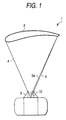
- a flight vehicle (hereinafter called the 'airframe') 1 having a parafoil includes, for example, a wing-like parafoil 2, a payload carrying frame 3 that is loaded with main equipment, a number of suspension lines 4, and a left and a right control line 5a and 5b (showing only one of them).
- the payload carrying frame 3 is suspended by the parafoil 2 via many suspension lines 4 in flight, and the lengths of tugging the control lines 5a and 5b are adjusted by a navigation guidance control unit 10 mounted in the upper portion of the payload carrying frame 3, so that the traveling direction is controlled.
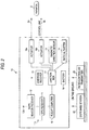
- the navigation guidance control unit 10 includes, as shown in Fig. 2, a GPS receiver 11, a DGPS beacon receiver 12, a magnetic direction sensor 13, a radio altimeter 14, an override receiver 15, a flight computer 16, a junction box 17, actuators 18a and 18b for DC motors and the like, and a battery 19.
- Antennas 11a and 12a are provided for the GPS receiver 11 and the DGPS beacon receiver 12, respectively.
- a DGPS base station 21 and a radio-controlled transmitter 22 are installed on the ground.
- the GPS receiver 11 together with the DGPS beacon receiver 12 functions as a DGPS for providing the ground speed and present position of the airframe 1 in real time.
- the GPS is usable alone.
- the magnetic direction sensor 13 is used to detect the azimuth of the airframe, and the radio altimeter 14 to detect the altitude thereof.
- These pieces of information are input to the flight computer 16 and utilized as means for estimating the wind velocity and wind direction.
- the flight computer 16 during automatic flight functions as a means for determining a flight path including speed, altitude, flight direction and the like to be followed on the basis of the information thus acquired.
- the flight computer 16 supplies control instructions to the actuators 18a and 18b and functions as a flight control means for adjusting the flight azimuth of the airframe 1 by adjusting lengths of tugging the left and right control lines 5a and 5b to turn the parafoil 2. With the control instruction to simultaneously tug the left and right control lines 5a and 5b, the flight computer 16 also operates to adjust a flight-path slope including forward airspeed, descent velocity and the like.
- the override receiver 15 Under instructions from the radio-controlled transmitter 22 operated by a radio controller on the ground, for example, the override receiver 15 is used to give detailed guidance at the time of emergency or landing. While this override function is actuated, the instructions about operating the actuators 18a and 18b and controlling the airframe 1 are issued from the radio-controlled transmitter 22 and priority is given over the instructions of the navigation guidance control unit 10 mounted in the airframe 1.
- a flight maneuver to be taken now is determined by the flight computer 16 so that the airframe may land at a target grounding point when the altitude becomes zero and control instructions are output to the actuators 18a and 18b in order to realize the maneuver.
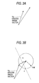
- the flight computer 16 is used to obtain two ground speed vectors Vg as shown in Fig. 3A on the basis of information from the override receiver 15, the DGPS beacon receiver 12, the DGPS base station 21 or GPS receiver 11 alone by making the airframe 1 do a steady turn. Then an intersecting point c between the vertical bisector a of a straight line connecting the front ends of the ground speed vectors Vg and a circle of ⁇ va ⁇ with the end-to-end length of the ground speed vectors Vg as its radius is mathematically obtained as shown in Fig. 3B. This point c is the center of turn as seen from the atmosphere.
- An airspeed vector Va necessary for use at this time may be an estimated value or a measured value resulting from using an air data sensor capable of measuring the airspeed vector Va of air.
- the centers of the circle estimated from data on several ground speed vectors are subjected to statistical processing; specifically, what shows less dispersion of estimated results of a plurality of centers of the circle is used as an actual center of the circle. Consequently, acquisition of a plurality of data points by making the airframe 1 have at least a half-turn is preferred.
- the estimated center of the circle has the wind vector Vw as shown in Fig. 4 and the wind estimation can be made by estimating the center of the turning circle.
- Fig. 5 shows a wind estimating method 2 by means of the DGPS and magnetic direction sensor 13 as another example which will be described below.
- the ground speed vectors Vg are then obtained on the basis of information from the GPS receiver 11, the DGPS beacon receiver 12, the DGPS base station 21 or GPS receiver 11 alone. Further, the azimuth of the airframe 1 estimated by the magnetic direction sensor 13, that is, a wind vector Vw is estimated from the traveling direction and roughly calculated by the following equation. An estimated value may be used for the airspeed vector Va that is needed at this time or otherwise a measured value using the air data sensor capable of measuring the airspeed vector Va of the air may also be used then.
- X w Vg ⁇ sin( ⁇ g)+Va ⁇ sin( ⁇ a)
- Y w Vg ⁇ cos( ⁇ g)+Va ⁇ cos( ⁇ a)
- the airspeed vector Va is also constant in the quasi-equilibrium gliding condition and regardless of presence or absence of wind, the forward speed and the descent velocity relative to the air will not vary greatly.
- This guidance law is not intended to guide the airframe 1 on the coordinates relative to the ground but to guide the airframe 1 on the coordinates relative to moving air, whereby greater accuracy of descent can be attained with the same guidance law under any condition ranging from no-wind to moderate gale exceeding the forward airspeed of the airframe 1.
- a quasi-target grounding point that is important in the coordinates relative to the ground will be described by reference to Fig. 6.
- the air mass and ground coordinates of guidance are set so that the +direction of the Y-axis may directly face the wind. While the ground coordinates are such that a target grounding point A is fixed to the origin thereof, the air mass coordinates move to the leeward (one direction) on the Y-axis of the ground coordinates with the quasi-target grounding point B always moved by the present altitude and wind velocity as an origin. Although the quasi-target grounding point B is always offset to the windward of the actual target grounding point A, this is due to taking into consideration the movement of the atmosphere, that is, the wind effect beforehand.
- the distance D decreases as the altitude H lowers and when the altitude H becomes zero, that is, at the point of time the airframe 1 lands, the quasi-target grounding point B coincides with the actual target. Therefore, the airframe 1 can be guided theoretically without being affected by the wind by guiding the airframe 1 to the quasi-target grounding point B as the origin of the ground coordinates at all times.
- Altitude adjustment is important in view of securing greater accuracy of descent of the airframe 1.
- the point is how to process the altitude near the target grounding point A with efficiency and there are a continuous and a race track turn method, for example, for the altitude processing.
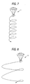
- This continuous turn is the most efficient method of processing the altitude that makes the most of the characteristics of the parafoil having a smaller turning radius than that of the flight vehicle.
- the altitude may be processed on a substantially fixed point by continuously turning the airframe 1 in the no-wind condition.
- the airframe 1 is turned by tugging the left or right control line 5a or 5b using the actuator 18a or 18b during the time expected to be necessary for its turn.
- the race track turn will subsequently be described.
- the airframe 1 is continuously turned while the wind exists under a certain condition, the turning airframe 1 is carried leeward at the same velocity as the wind velocity. While the airframe 1 is being continuously turned as shown in Fig. 8, the airframe 1 is periodically moved windward whereby to prevent the airframe 1 from unnecessarily departing from the target grounding point A according to this altitude processing method.
- the guidance law is constituted of five phases including wind estimation in phase 1; switching over to a nominal path, that is, a landing flight path in phase 2; altitude adjustment in phase 3; a final approach in phase 4; and a final flare in phase 5.
- a nominal path that is, a landing flight path in phase 2
- altitude adjustment in phase 3 a nominal path in phase 2
- a final approach in phase 4 a final flare in phase 5.
- wind velocity and wind direction are estimated at Step S2 in the phase 1; in other words, the initial value of the wind is estimated on the basis of the state quantity of the airframe obtained through the wind estimating method 1 using the DGPS or GPS alone by steadily turning the airframe 1 or the wind estimating method 2 using the DGPS and the magnetic direction sensor 13 by linearly traveling the airframe 1.
- the wind estimation is not limited to only the phase 1 but made in any other phase whenever the airframe 1 is steadily turned or linearly traveled so as to use the newest estimated value at all times.
- the landing flight path is determined by the flight computer 16 at Step S3 to determining the flight path according to the wind estimation.
- Step S4 to flight path guidance in the phase 2, the airframe 1 is moved along the path running in the same direction as the wind direction on the air coordinates. At this time, the airframe 1 travels in a direction perpendicular to the Y-axis of the air coordinates.
- the airframe 1 arrives at the landing flight path or a position close to the landing flight path at Step S 5 to changing the attitude, the airframe 1 is turned by tugging the right or left control line 5a or 5b during the time expected to be required for turning based on the turning performance thereof, and the airframe 1 travels on the landing flight path toward the leeward.
- the airframe 1 travels along the landing flight path on the assumption that it has already arrived at the landing flight path.
- the altitude adjustment in the phase 3 is made at the point of time the airframe 1 reaches the leeward from the quasi-target point B on the air coordinates.
- the landing flight path passes through the target grounding point A and is set at a near position parallel to a wind axis running in the same direction as the wind direction.
- the airframe 1 is prevented from being unnecessarily brought to the leeward by moving quickly onto the landing flight path.
- the airframe 1 enters the phase 3, that is, the continuous and race track turns when it is assumed necessary from the relation of the present position and the target grounding point A whereby to process the altitude, and descends while floating on the wind at path flight Step S7.
- the altitude adjustment is basically made by the continuous turn.
- the race track turn is made periodically as the airframe 1 floats leeward from the target and by making the airframe 1 travel windward, whereby the airframe 1 is prevented from unnecessarily departing from the target.
- the altitude adjustment in the phase 3 is intended to minimize the ground speed at the time of landing and ease the impact given to the payload and the final approach is made to direct the airframe 1 to the windward.
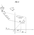
- the lift-drag ratio (L/D) is constant, the flight path toward the target exists only one path, so that the relation of the flight path of the final approach to the present position of the airframe 1 is as shown in Fig. 9.
- the start point DWP of the final approach of Fig. 9 is set close to the target by making the altitude adjustment so as to reduce the unnecessary movement of the airframe 1 to the leeward. Consequently, the flight path after the altitude adjustment is as shown by a solid line of Fig. 9.
- the flight change Step S8 in the phase 4 is followed in a stage where the start point DWP of the final approach becomes equal to a preset threshold or lower.
- the final approach is made by directing the airframe 1 windward in order to minimize the ground speed at the time of landing and reduce the impact given to the payload.
- the airframe 1 that has been traveling leeward prior to the phase 4 is caused to face the wind by 180° turning the airframe 1 and made to travel toward the target while correcting an azimuth error and a path angle error with respect to the target grounding point.
- an altimeter such as a radio altimeter is used to measure the relative distance between the airframe 1 and a ground plane and when the measured value comes to the threshold or lower, the airframe 1 is reduced in speed and made to soft-land by subjecting the airframe 1 to full flare, that is, tugging the control lines 5a and 5b by the same length.
- the payload is fixed to the payload carrying frame 3 prior to flight, loaded in the aircraft and dropped at the drop point set to ensure that the target grounding point is reached from the present position in consideration of the wind velocity and wind direction in the sky.
- the parafoil 2 opened by wind pressure in the air suspends the payload and is guided by the navigation guidance control unit 10 toward the target grounding point while gliding in a substantially balanced attitude; specifically, the airframe 1 is turned by tugging one of the left and right control lines 5a and 5b using the actuators 18a and 18b and landed at the target grounding point A accurately by changing the azimuth of the airframe in a desired direction or simultaneously tugging both the control lines 5a and 5b.
- the present invention can be implemented by suspending from the parafoil 2 an unmanned aircraft 51 as shown in Fig. 11 or a spacecraft 52 as shown in Fig. 12 in place of the payload carrying frame 3.
- a special navigation guidance control unit 10 can be loaded in that case, equipment mounted in the unmanned aircraft 51 or the spacecraft 52 is also usable.
- the unmanned aircraft 51 or the spacecraft 52 is made to travel toward a preset recovery area and on arriving at the recovery area after the termination of a predetermined flight or at the time of emergency, a parafoil-opening point is set so that the aircraft or spacecraft can reach the target recovery point based on the wind direction and velocity detected by an installed airspeed sensor. Then the unmanned aircraft or spacecraft can be guided and recovered in the same manner as what has been described in the aforementioned embodiment of the invention.
- the payload carrying frame 3 may be loaded with a payload 55 having an engine 57 with a propeller 56, a fuel tank 58 and the like.
- the airframe 1 rolls on the ground until the parafoil 2 obtains lift necessary for taking off from the thrust produced by the propeller 56 and after taking off, it cruises up to a target place like an ordinary aircraft.
- the traveling direction of the airframe 1 is controlled by properly tugging the left and right control lines 5a and 5b using the actuators and the airframe 1 is guided to a target grounding point through the operation described in the above embodiment of the invention after arrival at the target place.
- an automatic guidance system for guiding a flight vehicle having a parafoil to a target grounding point comprising the steps of: opening the parafoil of the flight vehicle dropped in a predetermined area above a grounding target point; estimating wind velocity and wind direction after the parafoil of the flight vehicle is opened; determining the landing flight path of the flight vehicle based on the estimated wind velocity and wind direction; guiding the flight of the flight vehicle to the determined landing flight path; and making the flight vehicle descend according to the landing flight path.
- the wind velocity and wind direction are estimated after the parafoil of the flight vehicle dropped in the predetermined area above the grounding target point is opened and the landing flight path of the flight vehicle is determined based on the estimated wind velocity and wind direction. Then the flight vehicle is made to descend along the determined landing flight path and accordingly an optimum landing flight path corresponding to the estimated wind velocity and wind direction is secured, whereby greater accuracy of descent can be attained.
- an automatic guidance system for a flight vehicle having a parafoil to a target grounding point comprises the steps of: opening the parafoil of the flight vehicle dropped in a predetermined area on the windward of and above a grounding target point; estimating wind velocity and wind direction after the parafoil of the flight vehicle is opened: determining a landing flight path according to which the flight vehicle descends from the windward to the leeward based on the estimated wind velocity and wind direction; guiding the flight of the flight vehicle to a position close to the determined landing flight path; changing the attitude of the flight vehicle so as to direct the flight vehicle to the leeward in the position close to the landing flight path; adjusting the altitude of the flight vehicle; making the flight vehicle with its altitude adjusted descend from the windward to the leeward according to the landing flight path; and making the flight vehicle land by changing the attitude of the flight vehicle so as to direct the flight vehicle windward on the leeward of the target grounding point.
- the step of adjusting the altitude of the flight vehicle is provided in addition to the first aspect of the invention. Accordingly, the flight vehicle is prevented from excessively floating leeward. Moreover, the flight vehicle is made to land by changing the attitude of the flight vehicle so as to direct the flight vehicle windward on the leeward of the target grounding point, whereby a landing impact is eased because the landing speed is suppressed.
- the estimation of the wind velocity and wind direction is calculated by the ground speed of the flight vehicle obtained by GPS or DGPS.
- the wind velocity and wind direction are efficiently estimated by the ground speed of the flight vehicle obtained by GPS or DGPS.
- the estimation of the wind velocity and wind direction is calculated by the ground speed of the flight vehicle, and the azimuth and airspeed of the flight vehicle obtained by GPS or DGPS.
- the wind velocity and wind direction are efficiently estimated by the ground speed of the flight vehicle and the azimuth and airspeed of the flight vehicle obtained by GPS or DGPS.
- the altitude adjustment of the flight vehicle is made by a continuous turn of the flight vehicle.
- the altitude adjustment of the flight vehicle is easily made by a continuous turn of the flight vehicle effectively utilizing the characteristics of the parafoil.
- a navigation guidance apparatus for a flight vehicle having a parafoil is such that the apparatus for guiding the flight vehicle having the parafoil to a target grounding point comprises wind-velocity and wind-direction estimating means for estimating wind velocity and wind direction after the parafoil of the flight vehicle is opened; land flight path determining means for determining the landing flight path of the flight vehicle based on the wind velocity and wind direction estimated by the wind-velocity and wind-direction estimating means; and flight control means for controlling the parafoil so that the flight vehicle descends according to a landing flight path determined by the flight path determining means.
- the provision of the wind-velocity and wind-direction estimating means for estimating wind velocity and wind direction, land flight path determining means for determining the landing flight path of the flight vehicle based on the wind velocity and wind direction, and flight control means for controlling the parafoil so that the flight vehicle descends according to the landing flight path makes the automatic guidance system of the first aspect to the fifith aspect of the invention attainable with efficiency.
- the wind-velocity and wind-direction estimating means includes a GPS receiver and a flight computer for estimating the wind velocity and wind direction based on ground speed vectors obtained by the GPS receiver.
- the flight computer is used to estimate the wind velocity and wind direction based on the ground speed vectors obtained by the GPS receiver as the flight vehicle travels.
- the wind-velocity and wind-direction estimating means includes a GPS receiver, a magnetic direction sensor for detecting the azimuth of the flight vehicle, and a flight computer for estimating the wind velocity and wind direction based on ground speed vectors obtained by the GPS receiver, the azimuth of the flight vehicle and the airspeed of the flight vehicle obtained by the magnetic direction sensor.
- the flight computer is used to estimate the wind velocity and wind direction based on the ground speed vectors obtained by the GPS receiver, the azimuth of the flight vehicle and the airspeed of the flight vehicle obtained by the magnetic direction sensor.
- the apparatus uses a DGPS beacon receiver in addition to the GPS receiver.
- the use of the DGPS beacon receiver in addition to the GPS receiver makes available the ground speed vectors with accuracy and also allows the wind velocity and wind direction to be estimated with accuracy.
- the flight path determining means is the flight computer for determining the flight path based on the wind velocity and the force of the wind that have been estimated and wherein the flight control means are actuators for tugging the control lines of the parafoil under the control of the flight computer.
- the flight path determining means is constituted of the flight computer and the flight control means are constituted of the flight computer and actuators for tugging the control lines of the parafoil.
Landscapes
- Engineering & Computer Science (AREA)
- Aviation & Aerospace Engineering (AREA)
- Radar, Positioning & Navigation (AREA)
- Remote Sensing (AREA)
- Physics & Mathematics (AREA)
- General Physics & Mathematics (AREA)
- Automation & Control Theory (AREA)
- Navigation (AREA)
- Control Of Position, Course, Altitude, Or Attitude Of Moving Bodies (AREA)
- Traffic Control Systems (AREA)
Applications Claiming Priority (2)
| Application Number | Priority Date | Filing Date | Title |
|---|---|---|---|
| JP33267298 | 1998-11-24 | ||
| JP33267298A JP4086384B2 (ja) | 1998-11-24 | 1998-11-24 | パラフォイルを備えた飛行体の自動誘導システム及びその航法誘導装置 |
Publications (3)
| Publication Number | Publication Date |
|---|---|
| EP1004952A2 true EP1004952A2 (fr) | 2000-05-31 |
| EP1004952A3 EP1004952A3 (fr) | 2001-03-14 |
| EP1004952B1 EP1004952B1 (fr) | 2005-06-15 |
Family
ID=18257595
Family Applications (1)
| Application Number | Title | Priority Date | Filing Date |
|---|---|---|---|
| EP99123182A Expired - Lifetime EP1004952B1 (fr) | 1998-11-24 | 1999-11-24 | Système de guidage automatique pour un engin volant comprenant un parapente et appareil de navigation pour un tel système |
Country Status (5)
| Country | Link |
|---|---|
| US (1) | US6343244B1 (fr) |
| EP (1) | EP1004952B1 (fr) |
| JP (1) | JP4086384B2 (fr) |
| CA (1) | CA2290118C (fr) |
| DE (1) | DE69925801T2 (fr) |
Cited By (5)
| Publication number | Priority date | Publication date | Assignee | Title |
|---|---|---|---|---|
| EP1463663A4 (fr) * | 2001-12-07 | 2009-08-05 | Atair Aerospace Inc | Systeme et procede pour le controle de parachute manoeuvrable |
| CN102749925A (zh) * | 2011-10-08 | 2012-10-24 | 张璞 | 伞降数字化避障语音引导设备 |
| DE10030036B4 (de) * | 2000-06-17 | 2014-07-17 | Eads Deutschland Gmbh | Fahrzeug-Steuerungssystem zur Bahnsteuerung unter Berücksichtigung einer das Fahrzeug beeinflussenden Strömung sowie ein Verfahren zur Erzeugung einer Bahn-Trajektorie |
| CN104142687A (zh) * | 2014-07-17 | 2014-11-12 | 西北工业大学 | 一种空间绳系机械臂目标抓捕后复合体姿态稳定控制方法 |
| CN111060106A (zh) * | 2019-12-30 | 2020-04-24 | 四川函钛科技有限公司 | 一种基于qar多维参数融合的飞机着陆轨迹修正方法 |
Families Citing this family (54)
| Publication number | Priority date | Publication date | Assignee | Title |
|---|---|---|---|---|
| US6587762B1 (en) * | 2000-08-18 | 2003-07-01 | Fxc Corporation | Automatic guidance unit for aerial delivery unit |
| JP4101474B2 (ja) * | 2001-05-16 | 2008-06-18 | 三菱重工業株式会社 | 航空機の飛行制御装置 |
| US20030025038A1 (en) * | 2001-08-06 | 2003-02-06 | Lockheed Martin Corporation | Autonomous control of a parafoil recovery system for UAVs |
| CA2469573A1 (fr) * | 2001-12-07 | 2003-06-19 | Atair Aerospace, Inc. | Vehicule multimode deployable |
| US7004836B2 (en) * | 2003-01-31 | 2006-02-28 | Igt | Gaming device having a die or dice directly associated with the reels in the primary game |
| JP4351897B2 (ja) * | 2003-11-11 | 2009-10-28 | 富士重工業株式会社 | 自律移動体、無人飛行船及び自律移動体の誘導方法 |
| JP4399287B2 (ja) * | 2004-02-09 | 2010-01-13 | 富士重工業株式会社 | 航空機及び航空機の風向推定方法 |
| JP4617990B2 (ja) * | 2005-04-28 | 2011-01-26 | 日本電気株式会社 | 自動飛行制御装置、自動飛行制御方法及び自動飛行制御プログラム |
| US8131405B2 (en) * | 2005-07-20 | 2012-03-06 | Atair Aerospace, Inc. | Method and apparatuses for controlling high wing loaded parafoils |
| JP4721347B2 (ja) * | 2006-01-10 | 2011-07-13 | 株式会社Ihiエアロスペース | 高速で帰還する帰還部材の回収方法及び回収装置 |
| FR2897712B1 (fr) * | 2006-02-20 | 2008-04-04 | Airbus France Sas | Dispositif d'aide au pilotage d'un aeronef lors d'une phase d'approche en vue d'un atterrissage. |
| KR100673524B1 (ko) * | 2006-04-20 | 2007-01-24 | 주식회사 코아블 | 파라포일 유도낙하산 운송시스템용 비행제어방법 |
| JP2007290647A (ja) * | 2006-04-27 | 2007-11-08 | Yamaha Motor Co Ltd | 無人ヘリコプタおよび外部環境推定装置 |
| US7703720B2 (en) | 2006-04-28 | 2010-04-27 | Pioneer Aerospace Corporation | Method and apparatus for parachute reefing control |
| CN101528538B (zh) * | 2006-09-14 | 2013-06-19 | 天帆有限两合公司 | 用于自由飞行、受约束的翼元件的操纵单元 |
| JP4957138B2 (ja) * | 2006-09-20 | 2012-06-20 | 保夫 木▲崎▼ | 回転翼航空機の回転翼 |
| JP4945752B2 (ja) * | 2006-11-07 | 2012-06-06 | 国立大学法人九州工業大学 | パラフォイルの飛行制御装置 |
| JP4925862B2 (ja) * | 2007-02-27 | 2012-05-09 | 三菱電機株式会社 | 計算機及び無人航空機 |
| US20100228406A1 (en) * | 2009-03-03 | 2010-09-09 | Honeywell International Inc. | UAV Flight Control Method And System |
| JP5166349B2 (ja) * | 2009-05-22 | 2013-03-21 | 株式会社日立製作所 | 固定翼機、固定翼機システムおよび固定翼機の着陸方法 |
| US20110251793A1 (en) * | 2010-02-16 | 2011-10-13 | Atair Aerospace, Inc. | Estimation of wind magnitude and direction |
| US8800930B1 (en) | 2010-03-22 | 2014-08-12 | The United States Of America As Represented By The Secretary Of The Navy | Aerial delivery system with high accuracy touchdown |
| US8437891B2 (en) * | 2010-04-13 | 2013-05-07 | The United States Of America As Represented By The Secretary Of The Navy | Method and apparatus for parafoil guidance that accounts for ground winds |
| CN102298385A (zh) * | 2011-04-29 | 2011-12-28 | 张璞 | 空军飞行员应急跳伞数字化安全降落控制装置 |
| US9014967B2 (en) | 2011-05-26 | 2015-04-21 | The Boeing Company | Airdrop controller system |
| US8571729B2 (en) * | 2012-02-08 | 2013-10-29 | The Boeing Company | Wind calculation system using a constant bank angle turn |
| US8781719B1 (en) * | 2012-07-02 | 2014-07-15 | The Boeing Company | High-low airdrop wind management |
| JP6128801B2 (ja) * | 2012-11-02 | 2017-05-17 | 株式会社Ihiエアロスペース | 空中発射システムの発射方位制御装置 |
| US20160137303A1 (en) * | 2013-06-18 | 2016-05-19 | Logos Technologies, Inc. | Systems and methods for using computer vision for parafoil flight control |
| US9508265B2 (en) * | 2014-07-24 | 2016-11-29 | The Charles Stark Draper Laboratory, Inc. | Methods and systems for wind mitigation in autonomous parafoil guidance |
| CN104267736B (zh) * | 2014-09-11 | 2017-05-17 | 中智科创机器人有限公司 | 一种帆船自主控制方法、装置及帆船 |
| CN104477416B (zh) * | 2014-12-03 | 2016-08-24 | 北京空间机电研究所 | 一种用于航天器减速着陆段多工作模式的风修正方法 |
| JP6195207B2 (ja) * | 2015-04-07 | 2017-09-13 | フジ・インバック株式会社 | 無人飛行機の狭地での発進及び回収方法 |
| CN105501261B (zh) * | 2015-11-24 | 2018-02-06 | 交控科技股份有限公司 | 一种恶劣天气下全自动驾驶方法、装置及系统 |
| KR101699797B1 (ko) | 2015-12-02 | 2017-02-01 | 정동호 | Gps유도 파라포일 공중운송 시스템 |
| KR101702573B1 (ko) * | 2015-12-07 | 2017-02-06 | 주식회사 누리텍 | 진보된 파라포일 공중운송시스템 |
| CN108369243B (zh) * | 2015-12-07 | 2020-09-18 | 乐天株式会社 | 风估计系统、风估计方法以及程序 |
| CN105867426B (zh) * | 2016-04-11 | 2018-08-21 | 西北工业大学 | 针对移动目标的飞机自动投放物资引导方法 |
| WO2017184806A1 (fr) * | 2016-04-20 | 2017-10-26 | Worcester Polytechnic Institute | Récupération de véhicule aéroporté |
| CN105912019A (zh) * | 2016-04-29 | 2016-08-31 | 南开大学 | 动力翼伞系统空投风场的辨识方法 |
| JP7046923B2 (ja) * | 2017-04-11 | 2022-04-04 | 日本化薬株式会社 | 飛行体および飛行体の制御方法 |
| JP6838656B2 (ja) * | 2017-06-30 | 2021-03-03 | 日本電気株式会社 | 着陸装置、着陸制御方法、着陸制御プログラム |
| CN108146639B (zh) * | 2018-01-03 | 2024-04-12 | 沈观清 | 用于中小型无人机回收的高速伞降系统、方法、及弹射伞 |
| JP6733948B2 (ja) * | 2018-02-28 | 2020-08-05 | 株式会社ナイルワークス | ドローン、その制御方法、および、制御プログラム |
| JP2020019463A (ja) * | 2018-08-03 | 2020-02-06 | 日本化薬株式会社 | パラシュートまたはパラグライダーの展開装置およびこれを備えた飛行体 |
| EP3858737A4 (fr) * | 2018-09-28 | 2022-06-08 | Nipponkayaku Kabushikikaisha | Corps volant pourvu d'un corps à déployer |
| JPWO2021002094A1 (fr) * | 2019-07-04 | 2021-01-07 | ||
| CN110598291B (zh) * | 2019-08-29 | 2023-01-17 | 中国航空工业集团公司沈阳飞机设计研究所 | 一种飞机十字形减速伞迎风投影面积折算系数的计算方法 |
| JP7332427B2 (ja) * | 2019-10-25 | 2023-08-23 | 慶應義塾 | パラシュート |
| CN112498741B (zh) * | 2020-10-30 | 2022-06-24 | 中南大学 | 一种探测飞行器及火星巡航探测的方法 |
| JP7510646B2 (ja) * | 2020-12-21 | 2024-07-04 | 紘基 河野 | 観測装置 |
| US12448130B1 (en) | 2024-04-17 | 2025-10-21 | United States Of America As Represented By The Secretary Of The Air Force | Steerable parachute for guiding a payload to a target |
| DE102024125332A1 (de) * | 2024-06-05 | 2025-12-11 | Neomium GmbH | Transport einer Last mittels eines Gleitschirms |
| JP7735018B1 (ja) * | 2025-04-18 | 2025-09-08 | コグニティブリサーチラボ株式会社 | 固定翼型無人飛行体システム及び固定翼型無人飛行体システムの制御方法 |
Family Cites Families (5)
| Publication number | Priority date | Publication date | Assignee | Title |
|---|---|---|---|---|
| DE433925C (de) | 1926-09-20 | Ronsdorfer Schlossfabrik Diede | Tuerschloss mit drehbarer Schliessfalle fuer Fahrzeuge | |
| JPH05185993A (ja) | 1992-01-09 | 1993-07-27 | Nissan Motor Co Ltd | グライディングパラシュートの誘導装置 |
| DE4306623A1 (en) | 1993-03-03 | 1993-08-05 | Heinz D Gehr | Land target system for parachute load - has computing unit comparing actual and required positions to determine corrective course achieved by positioning members |
| DE4336056A1 (de) | 1993-10-22 | 1995-04-27 | Nord Systemtechnik | Lenkbarer Fallschirm, insbesondere zur Beförderung von Lasten |
| JPH08156893A (ja) * | 1994-12-05 | 1996-06-18 | Mitsubishi Precision Co Ltd | パラシュート用誘導制御装置及びパラシュート誘導制御システム |
-
1998
- 1998-11-24 JP JP33267298A patent/JP4086384B2/ja not_active Expired - Lifetime
-
1999
- 1999-11-22 CA CA002290118A patent/CA2290118C/fr not_active Expired - Fee Related
- 1999-11-22 US US09/444,834 patent/US6343244B1/en not_active Expired - Lifetime
- 1999-11-24 EP EP99123182A patent/EP1004952B1/fr not_active Expired - Lifetime
- 1999-11-24 DE DE69925801T patent/DE69925801T2/de not_active Expired - Lifetime
Cited By (7)
| Publication number | Priority date | Publication date | Assignee | Title |
|---|---|---|---|---|
| DE10030036B4 (de) * | 2000-06-17 | 2014-07-17 | Eads Deutschland Gmbh | Fahrzeug-Steuerungssystem zur Bahnsteuerung unter Berücksichtigung einer das Fahrzeug beeinflussenden Strömung sowie ein Verfahren zur Erzeugung einer Bahn-Trajektorie |
| EP1463663A4 (fr) * | 2001-12-07 | 2009-08-05 | Atair Aerospace Inc | Systeme et procede pour le controle de parachute manoeuvrable |
| CN102749925A (zh) * | 2011-10-08 | 2012-10-24 | 张璞 | 伞降数字化避障语音引导设备 |
| CN104142687A (zh) * | 2014-07-17 | 2014-11-12 | 西北工业大学 | 一种空间绳系机械臂目标抓捕后复合体姿态稳定控制方法 |
| CN104142687B (zh) * | 2014-07-17 | 2017-01-11 | 西北工业大学 | 一种空间绳系机械臂目标抓捕后复合体姿态稳定控制方法 |
| CN111060106A (zh) * | 2019-12-30 | 2020-04-24 | 四川函钛科技有限公司 | 一种基于qar多维参数融合的飞机着陆轨迹修正方法 |
| CN111060106B (zh) * | 2019-12-30 | 2023-07-04 | 四川函钛科技有限公司 | 一种基于qar多维参数融合的飞机着陆轨迹修正方法 |
Also Published As
| Publication number | Publication date |
|---|---|
| DE69925801D1 (de) | 2005-07-21 |
| JP4086384B2 (ja) | 2008-05-14 |
| US6343244B1 (en) | 2002-01-29 |
| CA2290118C (fr) | 2007-07-10 |
| JP2000159192A (ja) | 2000-06-13 |
| EP1004952A3 (fr) | 2001-03-14 |
| EP1004952B1 (fr) | 2005-06-15 |
| DE69925801T2 (de) | 2005-11-03 |
| CA2290118A1 (fr) | 2000-05-24 |
Similar Documents
| Publication | Publication Date | Title |
|---|---|---|
| EP1004952B1 (fr) | Système de guidage automatique pour un engin volant comprenant un parapente et appareil de navigation pour un tel système | |
| EP3833600B1 (fr) | Localisation de site d'atterrissage pour la commande dynamique d'un aéronef vers un site d'atterrissage | |
| US6963795B2 (en) | Vehicle position keeping system | |
| US9939819B2 (en) | System and methods for automatically landing aircraft | |
| US6718236B1 (en) | Method for conducting a moving vehicle along a trajectory of a coordinated maneuver based on state information broadcast by other vehicles participating in the coordinated maneuver | |
| US6416019B1 (en) | Precision parachute recovery system | |
| US6338457B1 (en) | Precision parachute recovery system | |
| KR101494654B1 (ko) | 무인항공기 착륙유도 방법 및 장치와 착륙제어 방법 및 장치 | |
| US8108133B2 (en) | Vehicle position keeping system | |
| JP5083466B2 (ja) | 飛翔体の飛行状態制御装置 | |
| US9056679B1 (en) | System and method for airborne deployment of object designed for waterborne task | |
| US20220011785A1 (en) | Unmanned aerial vehicle control method and system based on moving base | |
| EP4026768B1 (fr) | Système de commande de position d'aéronef, aéronef et procédé de commande de position d'aéronef | |
| JPH06509297A (ja) | 自己誘導回収可能航空測定器モジュール | |
| CN111309041B (zh) | 一种弹射起飞拉起控制方法 | |
| JP2020149640A (ja) | 飛行システム及び着陸制御方法 | |
| CA2914291A1 (fr) | Procede de commande automatique de la phase de descente d'un aeronef au moyen d'un systeme d'avionique de bord executant un algorithme de descente | |
| CN114661065A (zh) | 固定翼无人机的起飞与降落系统及方法 | |
| US20230206774A1 (en) | Method and system for assisting with the approach of an aircraft with a view to landing | |
| US12509243B2 (en) | Automated towed glider control system | |
| EP4038464B1 (fr) | Usage conditionnel de vitesse commandée au lieu de la vitesse de l'air détectée pour informer des décisions de contrôle de vol | |
| KR100673524B1 (ko) | 파라포일 유도낙하산 운송시스템용 비행제어방법 | |
| US20070279254A1 (en) | Method and device to assist in the piloting of an aircraft | |
| CA2085566A1 (fr) | Systeme de decollage et d'atterrissage | |
| JPH05185993A (ja) | グライディングパラシュートの誘導装置 |
Legal Events
| Date | Code | Title | Description |
|---|---|---|---|
| PUAI | Public reference made under article 153(3) epc to a published international application that has entered the european phase |
Free format text: ORIGINAL CODE: 0009012 |
|
| AK | Designated contracting states |
Kind code of ref document: A2 Designated state(s): DE |
|
| AX | Request for extension of the european patent |
Free format text: AL;LT;LV;MK;RO;SI |
|
| PUAL | Search report despatched |
Free format text: ORIGINAL CODE: 0009013 |
|
| AK | Designated contracting states |
Kind code of ref document: A3 Designated state(s): AT BE CH CY DE DK ES FI FR GB GR IE IT LI LU MC NL PT SE |
|
| AX | Request for extension of the european patent |
Free format text: AL;LT;LV;MK;RO;SI |
|
| RIC1 | Information provided on ipc code assigned before grant |
Free format text: 7G 05D 1/10 A, 7B 64D 17/00 B |
|
| 17P | Request for examination filed |
Effective date: 20010629 |
|
| AKX | Designation fees paid |
Free format text: DE |
|
| 17Q | First examination report despatched |
Effective date: 20020801 |
|
| GRAP | Despatch of communication of intention to grant a patent |
Free format text: ORIGINAL CODE: EPIDOSNIGR1 |
|
| GRAS | Grant fee paid |
Free format text: ORIGINAL CODE: EPIDOSNIGR3 |
|
| GRAA | (expected) grant |
Free format text: ORIGINAL CODE: 0009210 |
|
| RIN1 | Information on inventor provided before grant (corrected) |
Inventor name: AMITO, ATSUSHI Inventor name: YONEDA, HIROSHI |
|
| AK | Designated contracting states |
Kind code of ref document: B1 Designated state(s): DE |
|
| REF | Corresponds to: |
Ref document number: 69925801 Country of ref document: DE Date of ref document: 20050721 Kind code of ref document: P |
|
| PLBE | No opposition filed within time limit |
Free format text: ORIGINAL CODE: 0009261 |
|
| STAA | Information on the status of an ep patent application or granted ep patent |
Free format text: STATUS: NO OPPOSITION FILED WITHIN TIME LIMIT |
|
| 26N | No opposition filed |
Effective date: 20060316 |
|
| PGFP | Annual fee paid to national office [announced via postgrant information from national office to epo] |
Ref country code: DE Payment date: 20131120 Year of fee payment: 15 |
|
| REG | Reference to a national code |
Ref country code: DE Ref legal event code: R119 Ref document number: 69925801 Country of ref document: DE |
|
| PG25 | Lapsed in a contracting state [announced via postgrant information from national office to epo] |
Ref country code: DE Free format text: LAPSE BECAUSE OF NON-PAYMENT OF DUE FEES Effective date: 20150602 |