EP1005030A1 - Gerät zum Abspielen von auf einer Informationsplatte gespeicherten Informationen - Google Patents
Gerät zum Abspielen von auf einer Informationsplatte gespeicherten Informationen Download PDFInfo
- Publication number
- EP1005030A1 EP1005030A1 EP99203836A EP99203836A EP1005030A1 EP 1005030 A1 EP1005030 A1 EP 1005030A1 EP 99203836 A EP99203836 A EP 99203836A EP 99203836 A EP99203836 A EP 99203836A EP 1005030 A1 EP1005030 A1 EP 1005030A1
- Authority
- EP
- European Patent Office
- Prior art keywords
- information
- lens unit
- information plate
- turntable
- rotating
- Prior art date
- Legal status (The legal status is an assumption and is not a legal conclusion. Google has not performed a legal analysis and makes no representation as to the accuracy of the status listed.)
- Withdrawn
Links
- 230000003287 optical effect Effects 0.000 claims abstract description 31
- 238000000034 method Methods 0.000 claims abstract description 3
- 238000005259 measurement Methods 0.000 description 2
- 230000001419 dependent effect Effects 0.000 description 1
Images
Classifications
-
- G—PHYSICS
- G11—INFORMATION STORAGE
- G11B—INFORMATION STORAGE BASED ON RELATIVE MOVEMENT BETWEEN RECORD CARRIER AND TRANSDUCER
- G11B7/00—Recording or reproducing by optical means, e.g. recording using a thermal beam of optical radiation by modifying optical properties or the physical structure, reproducing using an optical beam at lower power by sensing optical properties; Record carriers therefor
- G11B7/08—Disposition or mounting of heads or light sources relatively to record carriers
- G11B7/09—Disposition or mounting of heads or light sources relatively to record carriers with provision for moving the light beam or focus plane for the purpose of maintaining alignment of the light beam relative to the record carrier during transducing operation, e.g. to compensate for surface irregularities of the latter or for track following
- G11B7/095—Disposition or mounting of heads or light sources relatively to record carriers with provision for moving the light beam or focus plane for the purpose of maintaining alignment of the light beam relative to the record carrier during transducing operation, e.g. to compensate for surface irregularities of the latter or for track following specially adapted for discs, e.g. for compensation of eccentricity or wobble
- G11B7/0956—Disposition or mounting of heads or light sources relatively to record carriers with provision for moving the light beam or focus plane for the purpose of maintaining alignment of the light beam relative to the record carrier during transducing operation, e.g. to compensate for surface irregularities of the latter or for track following specially adapted for discs, e.g. for compensation of eccentricity or wobble to compensate for tilt, skew, warp or inclination of the disc, i.e. maintain the optical axis at right angles to the disc
-
- G—PHYSICS
- G11—INFORMATION STORAGE
- G11B—INFORMATION STORAGE BASED ON RELATIVE MOVEMENT BETWEEN RECORD CARRIER AND TRANSDUCER
- G11B7/00—Recording or reproducing by optical means, e.g. recording using a thermal beam of optical radiation by modifying optical properties or the physical structure, reproducing using an optical beam at lower power by sensing optical properties; Record carriers therefor
- G11B7/08—Disposition or mounting of heads or light sources relatively to record carriers
Definitions
- the invention relates to a device playing mm on an information plate stored information and / or for writing information on an information plate with a rotating turntable for rotating the information plate and a movable optical scanning unit for scanning the surface the information plate by means of an optical signal and a method for Angle setting of an optical scanning unit of a device for playing on an information plate stored information and / or for writing Information on an information plate, with a rotating drivable turntable is provided for rotation of the information plate and wherein the optical scanning unit is movable relative to the rotating information plate and for optical scanning the surface of the information plate is provided by means of an optical signal.
- Such a device is known for example from JP-A-03 228 229.
- This known device has adjusting screws on the turntable motor; by means of which one Alignment or adjustment of the turntable relative to the optical scanning unit is possible.
- Such adjustment is particularly high with information plates Storage density, e.g. DVD (Digital Video Disc) information plates, required because with such information plates, closer tolerances with regard to any Angular errors between the scanning unit and the information plate to be scanned as with conventional information discs according to the compact disc standard Need to become.
- Such angle errors are also referred to as tilt.
- the optical scanning unit an adjustable lens unit for guiding the optical signal with a Has adjusting device for adjusting the lens unit and that the Adjustment device is provided for an optimal angle adjustment of the Lens unit relative to an information disc rotating on the turntable to make.
- the device according to the invention has an adjustably mounted lens unit.
- the Lens unit has optical means for guiding and / or focusing an optical one Signal, especially a laser beam.
- an adjustment device for adjusting the Lens units can be used, for example, adjusting screws.
- the Lens unit is preferably pivotally mounted about two pivot axes, so that the angle between the output beam direction of the lens unit and one on the Turntable rotating information plate both in the radial direction and in tangential direction, i.e. in the direction of the information tracks on the information plate, is adjustable.
- an information plate is placed on the turntable and set in rotation.
- This Information plate used to adjust the lens unit is preferably a Reference information plate, which very precise and exact geometric dimensions and has optical properties. While the reference information plate is on the turntable rotates, the adjustment mechanism is used to make an exact adjustment the lens unit with respect to the reference information disc rotating on the turntable.
- the jitter value is preferably dependent as a measurement criterion used from the angle.
- Such an adjustable lens unit can be more easily and reliably Realize wisely.
- the scanning units of some manufacturers also already have a one-piece device for adjusting the lens unit to these known adjusting devices are however provided to the lens unit with respect to the housing of the Scanning unit or with regard to the mechanical guidance of the housing of the scanning unit align.
- An adjustment of the lens unit in the assembled module relative to However, the turntable or the information plate rotating on the turntable is not provided.
- this existing device can therefore also be used for Angle adjustment of the lens unit relative to one rotating on the turntable Information plate can be used.
- An additional adjustment mechanism on the Platter or platter motor is not required.
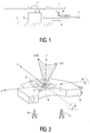
- Fig. 1 shows a device for playing on a circular information plate 1 stored information is provided.
- the information plate 1 is preferred an information disc with high storage density, for example an information disc according to the DVD (Digital Video Disc) standard.
- the information plate 1 is applied to a platter 2, in particular pressed on.
- the platter 2 is can be driven in rotation for a while 3 by means of a motor 4.
- the engine 4 is on one Chassis plate 5 of the device attached.
- an optical scanning unit 6 is provided, which in radial Direction x along a guide rail 7 by means of a not shown Drive mechanism is displaceable.
- the optical scanning unit 6 has one Lens unit 8, which is generated by means of a laser, not shown optical signal on the surface of the information plate 1 passes.
- the lens unit 8 is adjustable relative to the optical scanning unit 6. This enables one optimal angle setting of the lens unit relative to that on the platter 2 rotating information plate 1.
- the optical scanning unit 6 with the adjustably mounted lens unit 8 is in perspective View shown in Fig. 2.
- the lens unit 8 has at its center an exit lens 9.
- In the center of this output lens 9 is a Coordinate system x-y-z placed.
- the z-direction extends from the lens 9 in the direction the surface of the information plate 1.
- the x direction runs in the radial direction the rotating information plate 1 and the y-direction is tangent to the circular information tracks of the information plate 1.
- For optimal angle adjustment of the lens unit 8 with respect to the rotating information disc 1 are one first adjusting screw 10 and a second adjusting screw 11 are provided.
- the angle unit 8 can be pivoted about the axis y, whereby an angle ⁇ R is adjustable.
- the Lens unit 8 can be pivoted about the x-axis, whereby an angle ⁇ J is adjustable is.
- the angles ⁇ R and ⁇ J are each formed between the actual Beam direction of the laser beam directed onto the information plate and the optimal one Beam direction of the laser beam.
- the optimal beam direction can be determined by Adjust the pivoting of the lens unit 8. As a measurement criterion when setting the Lens unit 8, the jitter value is used depending on the angle.
Landscapes
- Moving Of The Head For Recording And Reproducing By Optical Means (AREA)
Abstract
Description
Claims (3)
- Gerät zum Abspielen von auf einer Informationsplatte gespeicherten Informationen und/oder zum Schreiben von Informationen auf eine Informationsplatte mit einem rotierend antreibbaren Plattenteller zur Rotation der Informationsplatte und einer bewegbaren optischen Abtasteinheit zur Abtastung der Oberfläche der Informationsplatte mittels eines optischen Signals, dadurch gekennzeichnet,
daß die optische Abtasteinheit eine verstellbar gelagerte Linseneinheit zur Führung des optischen Signals mit einer Einstellvorrichtung zur Verstellung der Linseneinheit aufweist und daß die Einstellvorrichtung dazu vorgesehen ist, eine optimale Winkeleinstellung der Linseneinheit relativ zu einer auf dem Plattenteller rotierenden Informationsplatte vorzunehmen. - Verfahren zur Winkeleinstellung einer optischen Abtasteinheit eines Gerätes zum Abspielen von auf einer Informationsplatte gespeicherten Informationen und/oder zum Schreiben von Informationen auf eine Informationsplatte, wobei ein rotierend antreibbarer Plattenteller zur Rotation der Informationsplatte vorgesehen ist und wobei die optische Abtasteinheit relativ zu der rotierenden Informationsplatte bewegbar ist und zur optischen Abtastung der Oberfläche der Informationsplatte mittels eines optischen Signals vorgesehen ist, dadurch gekennzeichnet,
daß die optische Abtasteinheit eine verstellbar gelagerte Linseneinheit zur Führung des optischen Signals mit einer Einstellvorrichtung zur Verstellung der Linseneinheit aufweist und daß mittels der Einstellvorrichtung eine optimale Winkeleinstellung der Linseneinheit relativ zu einer auf dem Plattenteller rotierenden Informationsplatte vorgenommen wird. - Verwendung einer verstellbar gelagerten Linseneinheit einer optischen Abtasteinheit eines Gerätes, das zum Abspielen von auf einer Informationsplatte gespeicherten Informationen und/oder zum Schreiben von Informationen auf eine Informationsplatte vorgesehen ist, zur optimalen Winkeleinstellung der Linseneinheit relativ zu einer auf einem Plattenteller des Gerätes rotierenden Informationsplatte.
Applications Claiming Priority (2)
| Application Number | Priority Date | Filing Date | Title |
|---|---|---|---|
| DE19854132 | 1998-11-24 | ||
| DE1998154132 DE19854132A1 (de) | 1998-11-24 | 1998-11-24 | Gerät zum Abspielen von auf einer Informationsplatte gespeicherten Informationen |
Publications (1)
| Publication Number | Publication Date |
|---|---|
| EP1005030A1 true EP1005030A1 (de) | 2000-05-31 |
Family
ID=7888813
Family Applications (1)
| Application Number | Title | Priority Date | Filing Date |
|---|---|---|---|
| EP99203836A Withdrawn EP1005030A1 (de) | 1998-11-24 | 1999-11-16 | Gerät zum Abspielen von auf einer Informationsplatte gespeicherten Informationen |
Country Status (3)
| Country | Link |
|---|---|
| EP (1) | EP1005030A1 (de) |
| JP (1) | JP2000182249A (de) |
| DE (1) | DE19854132A1 (de) |
Citations (2)
| Publication number | Priority date | Publication date | Assignee | Title |
|---|---|---|---|---|
| EP0538824A2 (de) * | 1991-10-22 | 1993-04-28 | SHARP Corporation | Neigungsabstimmungsgerät für Objektiv für optisches Anzeichnungs- und Wiedergabegerät |
| EP0649130A1 (de) * | 1993-10-15 | 1995-04-19 | Kabushiki Kaisha Kenwood | Vorrichtung zum Regeln der Neigung einer Objektivlinse für optische Abtasteinheit |
-
1998
- 1998-11-24 DE DE1998154132 patent/DE19854132A1/de not_active Withdrawn
-
1999
- 1999-11-16 EP EP99203836A patent/EP1005030A1/de not_active Withdrawn
- 1999-11-22 JP JP33180399A patent/JP2000182249A/ja active Pending
Patent Citations (2)
| Publication number | Priority date | Publication date | Assignee | Title |
|---|---|---|---|---|
| EP0538824A2 (de) * | 1991-10-22 | 1993-04-28 | SHARP Corporation | Neigungsabstimmungsgerät für Objektiv für optisches Anzeichnungs- und Wiedergabegerät |
| EP0649130A1 (de) * | 1993-10-15 | 1995-04-19 | Kabushiki Kaisha Kenwood | Vorrichtung zum Regeln der Neigung einer Objektivlinse für optische Abtasteinheit |
Also Published As
| Publication number | Publication date |
|---|---|
| JP2000182249A (ja) | 2000-06-30 |
| DE19854132A1 (de) | 2000-05-25 |
Similar Documents
| Publication | Publication Date | Title |
|---|---|---|
| DE3626029C2 (de) | ||
| DE68919893T2 (de) | Optische Kopfanordnungen für Plattenspieler. | |
| DE2462835C2 (de) | Vorrichtung zur Speicherung von Informationen auf einem Speicherelement | |
| DE2337015A1 (de) | Vorrichtung zur optischen abtastung einer rotierenden bildplatte | |
| DE69415762T2 (de) | Vorrichtung zum Regeln der Neigung einer Objektivlinse für optische Abtasteinheit | |
| DE69320346T2 (de) | Gerät und verfahren zur prüfung der ätzung von optischen servo-informationen auf magnetischen medien | |
| DE69521186T2 (de) | Galvanospiegel und damit versehenes Laufwerk für optische Platten | |
| DE69322836T2 (de) | Optische Platte | |
| DE4021115C2 (de) | Laufwerk für eine lesbare und beschreibbare optische Aufzeichnungs-Platte | |
| DE69832244T2 (de) | Vorrichtung zur Wiedergabe und Aufzeichnung eines optischen Speichermedium | |
| DE69030429T2 (de) | Gerät mit optischem Kopf zur Verarbeitung von Daten | |
| DE3607637C2 (de) | ||
| DE3873005T2 (de) | Optischer plattenspieler. | |
| DE68921140T2 (de) | Optischer Plattenspieler. | |
| CH678122A5 (de) | ||
| DE68924120T2 (de) | Optische Kopfanordnung. | |
| DE19503165C2 (de) | Optisches Aufzeichnungs- und Wiedergabesystem | |
| DE69518142T2 (de) | Optische platte und aufzeichnungs- und/oder wiedergabegerät | |
| DE69319773T2 (de) | Magnetkopfverwendende magneto-optische Informationsaufnahme und -wiedergabegerät und -verfahren | |
| DE3637947A1 (de) | Optische schreib/lese-vorrichtung | |
| DE2607275C3 (de) | Lichtstrahl-Abtasteinrichtung | |
| DE3887657T2 (de) | Optischer Kopf. | |
| EP1005030A1 (de) | Gerät zum Abspielen von auf einer Informationsplatte gespeicherten Informationen | |
| DE68907497T2 (de) | Elektro-optische Anordnung. | |
| DE69617873T2 (de) | Optischer Kopf für Informationsaufzeichnungs-/-wiedergabegerät |
Legal Events
| Date | Code | Title | Description |
|---|---|---|---|
| PUAI | Public reference made under article 153(3) epc to a published international application that has entered the european phase |
Free format text: ORIGINAL CODE: 0009012 |
|
| AK | Designated contracting states |
Kind code of ref document: A1 Designated state(s): BE DE FR GB |
|
| AX | Request for extension of the european patent |
Free format text: AL;LT;LV;MK;RO;SI |
|
| 17P | Request for examination filed |
Effective date: 20001130 |
|
| AKX | Designation fees paid |
Free format text: BE DE FR GB |
|
| RAP1 | Party data changed (applicant data changed or rights of an application transferred) |
Owner name: KONINKLIJKE PHILIPS ELECTRONICS N.V. Owner name: PHILIPS CORPORATE INTELLECTUAL PROPERTY GMBH |
|
| RAP1 | Party data changed (applicant data changed or rights of an application transferred) |
Owner name: KONINKLIJKE PHILIPS ELECTRONICS N.V. Owner name: PHILIPS INTELLECTUAL PROPERTY & STANDARDS GMBH |
|
| STAA | Information on the status of an ep patent application or granted ep patent |
Free format text: STATUS: THE APPLICATION HAS BEEN WITHDRAWN |
|
| 18W | Application withdrawn |
Effective date: 20041123 |