EP1005036B1 - Optisches Informationsaufzeichnungsmedium - Google Patents
Optisches Informationsaufzeichnungsmedium Download PDFInfo
- Publication number
- EP1005036B1 EP1005036B1 EP99123167A EP99123167A EP1005036B1 EP 1005036 B1 EP1005036 B1 EP 1005036B1 EP 99123167 A EP99123167 A EP 99123167A EP 99123167 A EP99123167 A EP 99123167A EP 1005036 B1 EP1005036 B1 EP 1005036B1
- Authority
- EP
- European Patent Office
- Prior art keywords
- layer
- medium
- recording
- thermal diffusion
- optical information
- Prior art date
- Legal status (The legal status is an assumption and is not a legal conclusion. Google has not performed a legal analysis and makes no representation as to the accuracy of the status listed.)
- Expired - Lifetime
Links
Images


Classifications
-
- G—PHYSICS
- G11—INFORMATION STORAGE
- G11B—INFORMATION STORAGE BASED ON RELATIVE MOVEMENT BETWEEN RECORD CARRIER AND TRANSDUCER
- G11B7/00—Recording or reproducing by optical means, e.g. recording using a thermal beam of optical radiation by modifying optical properties or the physical structure, reproducing using an optical beam at lower power by sensing optical properties; Record carriers therefor
- G11B7/24—Record carriers characterised by shape, structure or physical properties, or by the selection of the material
- G11B7/2403—Layers; Shape, structure or physical properties thereof
-
- G—PHYSICS
- G11—INFORMATION STORAGE
- G11B—INFORMATION STORAGE BASED ON RELATIVE MOVEMENT BETWEEN RECORD CARRIER AND TRANSDUCER
- G11B7/00—Recording or reproducing by optical means, e.g. recording using a thermal beam of optical radiation by modifying optical properties or the physical structure, reproducing using an optical beam at lower power by sensing optical properties; Record carriers therefor
- G11B7/24—Record carriers characterised by shape, structure or physical properties, or by the selection of the material
- G11B7/241—Record carriers characterised by shape, structure or physical properties, or by the selection of the material characterised by the selection of the material
- G11B7/252—Record carriers characterised by shape, structure or physical properties, or by the selection of the material characterised by the selection of the material of layers other than recording layers
- G11B7/254—Record carriers characterised by shape, structure or physical properties, or by the selection of the material characterised by the selection of the material of layers other than recording layers of protective topcoat layers
- G11B7/2548—Record carriers characterised by shape, structure or physical properties, or by the selection of the material characterised by the selection of the material of layers other than recording layers of protective topcoat layers consisting essentially of inorganic materials
-
- G—PHYSICS
- G11—INFORMATION STORAGE
- G11B—INFORMATION STORAGE BASED ON RELATIVE MOVEMENT BETWEEN RECORD CARRIER AND TRANSDUCER
- G11B7/00—Recording or reproducing by optical means, e.g. recording using a thermal beam of optical radiation by modifying optical properties or the physical structure, reproducing using an optical beam at lower power by sensing optical properties; Record carriers therefor
- G11B7/24—Record carriers characterised by shape, structure or physical properties, or by the selection of the material
- G11B7/241—Record carriers characterised by shape, structure or physical properties, or by the selection of the material characterised by the selection of the material
- G11B7/242—Record carriers characterised by shape, structure or physical properties, or by the selection of the material characterised by the selection of the material of recording layers
- G11B7/243—Record carriers characterised by shape, structure or physical properties, or by the selection of the material characterised by the selection of the material of recording layers comprising inorganic materials only, e.g. ablative layers
- G11B2007/24302—Metals or metalloids
- G11B2007/24304—Metals or metalloids group 2 or 12 elements (e.g. Be, Ca, Mg, Zn, Cd)
-
- G—PHYSICS
- G11—INFORMATION STORAGE
- G11B—INFORMATION STORAGE BASED ON RELATIVE MOVEMENT BETWEEN RECORD CARRIER AND TRANSDUCER
- G11B7/00—Recording or reproducing by optical means, e.g. recording using a thermal beam of optical radiation by modifying optical properties or the physical structure, reproducing using an optical beam at lower power by sensing optical properties; Record carriers therefor
- G11B7/24—Record carriers characterised by shape, structure or physical properties, or by the selection of the material
- G11B7/241—Record carriers characterised by shape, structure or physical properties, or by the selection of the material characterised by the selection of the material
- G11B7/242—Record carriers characterised by shape, structure or physical properties, or by the selection of the material characterised by the selection of the material of recording layers
- G11B7/243—Record carriers characterised by shape, structure or physical properties, or by the selection of the material characterised by the selection of the material of recording layers comprising inorganic materials only, e.g. ablative layers
- G11B2007/24302—Metals or metalloids
- G11B2007/24308—Metals or metalloids transition metal elements of group 11 (Cu, Ag, Au)
-
- G—PHYSICS
- G11—INFORMATION STORAGE
- G11B—INFORMATION STORAGE BASED ON RELATIVE MOVEMENT BETWEEN RECORD CARRIER AND TRANSDUCER
- G11B7/00—Recording or reproducing by optical means, e.g. recording using a thermal beam of optical radiation by modifying optical properties or the physical structure, reproducing using an optical beam at lower power by sensing optical properties; Record carriers therefor
- G11B7/24—Record carriers characterised by shape, structure or physical properties, or by the selection of the material
- G11B7/241—Record carriers characterised by shape, structure or physical properties, or by the selection of the material characterised by the selection of the material
- G11B7/242—Record carriers characterised by shape, structure or physical properties, or by the selection of the material characterised by the selection of the material of recording layers
- G11B7/243—Record carriers characterised by shape, structure or physical properties, or by the selection of the material characterised by the selection of the material of recording layers comprising inorganic materials only, e.g. ablative layers
- G11B2007/24302—Metals or metalloids
- G11B2007/2431—Metals or metalloids group 13 elements (B, Al, Ga, In)
-
- G—PHYSICS
- G11—INFORMATION STORAGE
- G11B—INFORMATION STORAGE BASED ON RELATIVE MOVEMENT BETWEEN RECORD CARRIER AND TRANSDUCER
- G11B7/00—Recording or reproducing by optical means, e.g. recording using a thermal beam of optical radiation by modifying optical properties or the physical structure, reproducing using an optical beam at lower power by sensing optical properties; Record carriers therefor
- G11B7/24—Record carriers characterised by shape, structure or physical properties, or by the selection of the material
- G11B7/241—Record carriers characterised by shape, structure or physical properties, or by the selection of the material characterised by the selection of the material
- G11B7/242—Record carriers characterised by shape, structure or physical properties, or by the selection of the material characterised by the selection of the material of recording layers
- G11B7/243—Record carriers characterised by shape, structure or physical properties, or by the selection of the material characterised by the selection of the material of recording layers comprising inorganic materials only, e.g. ablative layers
- G11B2007/24302—Metals or metalloids
- G11B2007/24312—Metals or metalloids group 14 elements (e.g. Si, Ge, Sn)
-
- G—PHYSICS
- G11—INFORMATION STORAGE
- G11B—INFORMATION STORAGE BASED ON RELATIVE MOVEMENT BETWEEN RECORD CARRIER AND TRANSDUCER
- G11B7/00—Recording or reproducing by optical means, e.g. recording using a thermal beam of optical radiation by modifying optical properties or the physical structure, reproducing using an optical beam at lower power by sensing optical properties; Record carriers therefor
- G11B7/24—Record carriers characterised by shape, structure or physical properties, or by the selection of the material
- G11B7/241—Record carriers characterised by shape, structure or physical properties, or by the selection of the material characterised by the selection of the material
- G11B7/242—Record carriers characterised by shape, structure or physical properties, or by the selection of the material characterised by the selection of the material of recording layers
- G11B7/243—Record carriers characterised by shape, structure or physical properties, or by the selection of the material characterised by the selection of the material of recording layers comprising inorganic materials only, e.g. ablative layers
- G11B2007/24302—Metals or metalloids
- G11B2007/24314—Metals or metalloids group 15 elements (e.g. Sb, Bi)
-
- G—PHYSICS
- G11—INFORMATION STORAGE
- G11B—INFORMATION STORAGE BASED ON RELATIVE MOVEMENT BETWEEN RECORD CARRIER AND TRANSDUCER
- G11B7/00—Recording or reproducing by optical means, e.g. recording using a thermal beam of optical radiation by modifying optical properties or the physical structure, reproducing using an optical beam at lower power by sensing optical properties; Record carriers therefor
- G11B7/24—Record carriers characterised by shape, structure or physical properties, or by the selection of the material
- G11B7/241—Record carriers characterised by shape, structure or physical properties, or by the selection of the material characterised by the selection of the material
- G11B7/242—Record carriers characterised by shape, structure or physical properties, or by the selection of the material characterised by the selection of the material of recording layers
- G11B7/243—Record carriers characterised by shape, structure or physical properties, or by the selection of the material characterised by the selection of the material of recording layers comprising inorganic materials only, e.g. ablative layers
- G11B2007/24302—Metals or metalloids
- G11B2007/24316—Metals or metalloids group 16 elements (i.e. chalcogenides, Se, Te)
-
- G—PHYSICS
- G11—INFORMATION STORAGE
- G11B—INFORMATION STORAGE BASED ON RELATIVE MOVEMENT BETWEEN RECORD CARRIER AND TRANSDUCER
- G11B7/00—Recording or reproducing by optical means, e.g. recording using a thermal beam of optical radiation by modifying optical properties or the physical structure, reproducing using an optical beam at lower power by sensing optical properties; Record carriers therefor
- G11B7/24—Record carriers characterised by shape, structure or physical properties, or by the selection of the material
- G11B7/241—Record carriers characterised by shape, structure or physical properties, or by the selection of the material characterised by the selection of the material
- G11B7/252—Record carriers characterised by shape, structure or physical properties, or by the selection of the material characterised by the selection of the material of layers other than recording layers
- G11B7/254—Record carriers characterised by shape, structure or physical properties, or by the selection of the material characterised by the selection of the material of layers other than recording layers of protective topcoat layers
- G11B2007/25408—Record carriers characterised by shape, structure or physical properties, or by the selection of the material characterised by the selection of the material of layers other than recording layers of protective topcoat layers consisting essentially of inorganic materials
- G11B2007/25411—Record carriers characterised by shape, structure or physical properties, or by the selection of the material characterised by the selection of the material of layers other than recording layers of protective topcoat layers consisting essentially of inorganic materials containing transition metal elements (Zn, Fe, Co, Ni, Pt)
-
- G—PHYSICS
- G11—INFORMATION STORAGE
- G11B—INFORMATION STORAGE BASED ON RELATIVE MOVEMENT BETWEEN RECORD CARRIER AND TRANSDUCER
- G11B7/00—Recording or reproducing by optical means, e.g. recording using a thermal beam of optical radiation by modifying optical properties or the physical structure, reproducing using an optical beam at lower power by sensing optical properties; Record carriers therefor
- G11B7/24—Record carriers characterised by shape, structure or physical properties, or by the selection of the material
- G11B7/241—Record carriers characterised by shape, structure or physical properties, or by the selection of the material characterised by the selection of the material
- G11B7/252—Record carriers characterised by shape, structure or physical properties, or by the selection of the material characterised by the selection of the material of layers other than recording layers
- G11B7/254—Record carriers characterised by shape, structure or physical properties, or by the selection of the material characterised by the selection of the material of layers other than recording layers of protective topcoat layers
- G11B2007/25408—Record carriers characterised by shape, structure or physical properties, or by the selection of the material characterised by the selection of the material of layers other than recording layers of protective topcoat layers consisting essentially of inorganic materials
- G11B2007/25414—Record carriers characterised by shape, structure or physical properties, or by the selection of the material characterised by the selection of the material of layers other than recording layers of protective topcoat layers consisting essentially of inorganic materials containing Group 13 elements (B, Al, Ga)
-
- G—PHYSICS
- G11—INFORMATION STORAGE
- G11B—INFORMATION STORAGE BASED ON RELATIVE MOVEMENT BETWEEN RECORD CARRIER AND TRANSDUCER
- G11B7/00—Recording or reproducing by optical means, e.g. recording using a thermal beam of optical radiation by modifying optical properties or the physical structure, reproducing using an optical beam at lower power by sensing optical properties; Record carriers therefor
- G11B7/24—Record carriers characterised by shape, structure or physical properties, or by the selection of the material
- G11B7/241—Record carriers characterised by shape, structure or physical properties, or by the selection of the material characterised by the selection of the material
- G11B7/252—Record carriers characterised by shape, structure or physical properties, or by the selection of the material characterised by the selection of the material of layers other than recording layers
- G11B7/254—Record carriers characterised by shape, structure or physical properties, or by the selection of the material characterised by the selection of the material of layers other than recording layers of protective topcoat layers
- G11B2007/25408—Record carriers characterised by shape, structure or physical properties, or by the selection of the material characterised by the selection of the material of layers other than recording layers of protective topcoat layers consisting essentially of inorganic materials
- G11B2007/25417—Record carriers characterised by shape, structure or physical properties, or by the selection of the material characterised by the selection of the material of layers other than recording layers of protective topcoat layers consisting essentially of inorganic materials containing Group 14 elements (C, Si, Ge, Sn)
-
- G—PHYSICS
- G11—INFORMATION STORAGE
- G11B—INFORMATION STORAGE BASED ON RELATIVE MOVEMENT BETWEEN RECORD CARRIER AND TRANSDUCER
- G11B7/00—Recording or reproducing by optical means, e.g. recording using a thermal beam of optical radiation by modifying optical properties or the physical structure, reproducing using an optical beam at lower power by sensing optical properties; Record carriers therefor
- G11B7/24—Record carriers characterised by shape, structure or physical properties, or by the selection of the material
- G11B7/241—Record carriers characterised by shape, structure or physical properties, or by the selection of the material characterised by the selection of the material
- G11B7/252—Record carriers characterised by shape, structure or physical properties, or by the selection of the material characterised by the selection of the material of layers other than recording layers
- G11B7/257—Record carriers characterised by shape, structure or physical properties, or by the selection of the material characterised by the selection of the material of layers other than recording layers of layers having properties involved in recording or reproduction, e.g. optical interference layers or sensitising layers or dielectric layers, which are protecting the recording layers
- G11B2007/25705—Record carriers characterised by shape, structure or physical properties, or by the selection of the material characterised by the selection of the material of layers other than recording layers of layers having properties involved in recording or reproduction, e.g. optical interference layers or sensitising layers or dielectric layers, which are protecting the recording layers consisting essentially of inorganic materials
- G11B2007/25706—Record carriers characterised by shape, structure or physical properties, or by the selection of the material characterised by the selection of the material of layers other than recording layers of layers having properties involved in recording or reproduction, e.g. optical interference layers or sensitising layers or dielectric layers, which are protecting the recording layers consisting essentially of inorganic materials containing transition metal elements (Zn, Fe, Co, Ni, Pt)
-
- G—PHYSICS
- G11—INFORMATION STORAGE
- G11B—INFORMATION STORAGE BASED ON RELATIVE MOVEMENT BETWEEN RECORD CARRIER AND TRANSDUCER
- G11B7/00—Recording or reproducing by optical means, e.g. recording using a thermal beam of optical radiation by modifying optical properties or the physical structure, reproducing using an optical beam at lower power by sensing optical properties; Record carriers therefor
- G11B7/24—Record carriers characterised by shape, structure or physical properties, or by the selection of the material
- G11B7/241—Record carriers characterised by shape, structure or physical properties, or by the selection of the material characterised by the selection of the material
- G11B7/252—Record carriers characterised by shape, structure or physical properties, or by the selection of the material characterised by the selection of the material of layers other than recording layers
- G11B7/257—Record carriers characterised by shape, structure or physical properties, or by the selection of the material characterised by the selection of the material of layers other than recording layers of layers having properties involved in recording or reproduction, e.g. optical interference layers or sensitising layers or dielectric layers, which are protecting the recording layers
- G11B2007/25705—Record carriers characterised by shape, structure or physical properties, or by the selection of the material characterised by the selection of the material of layers other than recording layers of layers having properties involved in recording or reproduction, e.g. optical interference layers or sensitising layers or dielectric layers, which are protecting the recording layers consisting essentially of inorganic materials
- G11B2007/25708—Record carriers characterised by shape, structure or physical properties, or by the selection of the material characterised by the selection of the material of layers other than recording layers of layers having properties involved in recording or reproduction, e.g. optical interference layers or sensitising layers or dielectric layers, which are protecting the recording layers consisting essentially of inorganic materials containing group 13 elements (B, Al, Ga)
-
- G—PHYSICS
- G11—INFORMATION STORAGE
- G11B—INFORMATION STORAGE BASED ON RELATIVE MOVEMENT BETWEEN RECORD CARRIER AND TRANSDUCER
- G11B7/00—Recording or reproducing by optical means, e.g. recording using a thermal beam of optical radiation by modifying optical properties or the physical structure, reproducing using an optical beam at lower power by sensing optical properties; Record carriers therefor
- G11B7/24—Record carriers characterised by shape, structure or physical properties, or by the selection of the material
- G11B7/241—Record carriers characterised by shape, structure or physical properties, or by the selection of the material characterised by the selection of the material
- G11B7/252—Record carriers characterised by shape, structure or physical properties, or by the selection of the material characterised by the selection of the material of layers other than recording layers
- G11B7/257—Record carriers characterised by shape, structure or physical properties, or by the selection of the material characterised by the selection of the material of layers other than recording layers of layers having properties involved in recording or reproduction, e.g. optical interference layers or sensitising layers or dielectric layers, which are protecting the recording layers
- G11B2007/25705—Record carriers characterised by shape, structure or physical properties, or by the selection of the material characterised by the selection of the material of layers other than recording layers of layers having properties involved in recording or reproduction, e.g. optical interference layers or sensitising layers or dielectric layers, which are protecting the recording layers consisting essentially of inorganic materials
- G11B2007/2571—Record carriers characterised by shape, structure or physical properties, or by the selection of the material characterised by the selection of the material of layers other than recording layers of layers having properties involved in recording or reproduction, e.g. optical interference layers or sensitising layers or dielectric layers, which are protecting the recording layers consisting essentially of inorganic materials containing group 14 elements except carbon (Si, Ge, Sn, Pb)
-
- G—PHYSICS
- G11—INFORMATION STORAGE
- G11B—INFORMATION STORAGE BASED ON RELATIVE MOVEMENT BETWEEN RECORD CARRIER AND TRANSDUCER
- G11B7/00—Recording or reproducing by optical means, e.g. recording using a thermal beam of optical radiation by modifying optical properties or the physical structure, reproducing using an optical beam at lower power by sensing optical properties; Record carriers therefor
- G11B7/24—Record carriers characterised by shape, structure or physical properties, or by the selection of the material
- G11B7/241—Record carriers characterised by shape, structure or physical properties, or by the selection of the material characterised by the selection of the material
- G11B7/252—Record carriers characterised by shape, structure or physical properties, or by the selection of the material characterised by the selection of the material of layers other than recording layers
- G11B7/257—Record carriers characterised by shape, structure or physical properties, or by the selection of the material characterised by the selection of the material of layers other than recording layers of layers having properties involved in recording or reproduction, e.g. optical interference layers or sensitising layers or dielectric layers, which are protecting the recording layers
- G11B2007/25705—Record carriers characterised by shape, structure or physical properties, or by the selection of the material characterised by the selection of the material of layers other than recording layers of layers having properties involved in recording or reproduction, e.g. optical interference layers or sensitising layers or dielectric layers, which are protecting the recording layers consisting essentially of inorganic materials
- G11B2007/25711—Record carriers characterised by shape, structure or physical properties, or by the selection of the material characterised by the selection of the material of layers other than recording layers of layers having properties involved in recording or reproduction, e.g. optical interference layers or sensitising layers or dielectric layers, which are protecting the recording layers consisting essentially of inorganic materials containing carbon
-
- G—PHYSICS
- G11—INFORMATION STORAGE
- G11B—INFORMATION STORAGE BASED ON RELATIVE MOVEMENT BETWEEN RECORD CARRIER AND TRANSDUCER
- G11B7/00—Recording or reproducing by optical means, e.g. recording using a thermal beam of optical radiation by modifying optical properties or the physical structure, reproducing using an optical beam at lower power by sensing optical properties; Record carriers therefor
- G11B7/24—Record carriers characterised by shape, structure or physical properties, or by the selection of the material
- G11B7/241—Record carriers characterised by shape, structure or physical properties, or by the selection of the material characterised by the selection of the material
- G11B7/252—Record carriers characterised by shape, structure or physical properties, or by the selection of the material characterised by the selection of the material of layers other than recording layers
- G11B7/257—Record carriers characterised by shape, structure or physical properties, or by the selection of the material characterised by the selection of the material of layers other than recording layers of layers having properties involved in recording or reproduction, e.g. optical interference layers or sensitising layers or dielectric layers, which are protecting the recording layers
- G11B2007/25705—Record carriers characterised by shape, structure or physical properties, or by the selection of the material characterised by the selection of the material of layers other than recording layers of layers having properties involved in recording or reproduction, e.g. optical interference layers or sensitising layers or dielectric layers, which are protecting the recording layers consisting essentially of inorganic materials
- G11B2007/25713—Record carriers characterised by shape, structure or physical properties, or by the selection of the material characterised by the selection of the material of layers other than recording layers of layers having properties involved in recording or reproduction, e.g. optical interference layers or sensitising layers or dielectric layers, which are protecting the recording layers consisting essentially of inorganic materials containing nitrogen
-
- G—PHYSICS
- G11—INFORMATION STORAGE
- G11B—INFORMATION STORAGE BASED ON RELATIVE MOVEMENT BETWEEN RECORD CARRIER AND TRANSDUCER
- G11B7/00—Recording or reproducing by optical means, e.g. recording using a thermal beam of optical radiation by modifying optical properties or the physical structure, reproducing using an optical beam at lower power by sensing optical properties; Record carriers therefor
- G11B7/24—Record carriers characterised by shape, structure or physical properties, or by the selection of the material
- G11B7/241—Record carriers characterised by shape, structure or physical properties, or by the selection of the material characterised by the selection of the material
- G11B7/252—Record carriers characterised by shape, structure or physical properties, or by the selection of the material characterised by the selection of the material of layers other than recording layers
- G11B7/257—Record carriers characterised by shape, structure or physical properties, or by the selection of the material characterised by the selection of the material of layers other than recording layers of layers having properties involved in recording or reproduction, e.g. optical interference layers or sensitising layers or dielectric layers, which are protecting the recording layers
- G11B2007/25705—Record carriers characterised by shape, structure or physical properties, or by the selection of the material characterised by the selection of the material of layers other than recording layers of layers having properties involved in recording or reproduction, e.g. optical interference layers or sensitising layers or dielectric layers, which are protecting the recording layers consisting essentially of inorganic materials
- G11B2007/25715—Record carriers characterised by shape, structure or physical properties, or by the selection of the material characterised by the selection of the material of layers other than recording layers of layers having properties involved in recording or reproduction, e.g. optical interference layers or sensitising layers or dielectric layers, which are protecting the recording layers consisting essentially of inorganic materials containing oxygen
-
- G—PHYSICS
- G11—INFORMATION STORAGE
- G11B—INFORMATION STORAGE BASED ON RELATIVE MOVEMENT BETWEEN RECORD CARRIER AND TRANSDUCER
- G11B7/00—Recording or reproducing by optical means, e.g. recording using a thermal beam of optical radiation by modifying optical properties or the physical structure, reproducing using an optical beam at lower power by sensing optical properties; Record carriers therefor
- G11B7/24—Record carriers characterised by shape, structure or physical properties, or by the selection of the material
- G11B7/241—Record carriers characterised by shape, structure or physical properties, or by the selection of the material characterised by the selection of the material
- G11B7/252—Record carriers characterised by shape, structure or physical properties, or by the selection of the material characterised by the selection of the material of layers other than recording layers
- G11B7/257—Record carriers characterised by shape, structure or physical properties, or by the selection of the material characterised by the selection of the material of layers other than recording layers of layers having properties involved in recording or reproduction, e.g. optical interference layers or sensitising layers or dielectric layers, which are protecting the recording layers
- G11B2007/25705—Record carriers characterised by shape, structure or physical properties, or by the selection of the material characterised by the selection of the material of layers other than recording layers of layers having properties involved in recording or reproduction, e.g. optical interference layers or sensitising layers or dielectric layers, which are protecting the recording layers consisting essentially of inorganic materials
- G11B2007/25716—Record carriers characterised by shape, structure or physical properties, or by the selection of the material characterised by the selection of the material of layers other than recording layers of layers having properties involved in recording or reproduction, e.g. optical interference layers or sensitising layers or dielectric layers, which are protecting the recording layers consisting essentially of inorganic materials containing sulfur
-
- G—PHYSICS
- G11—INFORMATION STORAGE
- G11B—INFORMATION STORAGE BASED ON RELATIVE MOVEMENT BETWEEN RECORD CARRIER AND TRANSDUCER
- G11B7/00—Recording or reproducing by optical means, e.g. recording using a thermal beam of optical radiation by modifying optical properties or the physical structure, reproducing using an optical beam at lower power by sensing optical properties; Record carriers therefor
- G11B7/24—Record carriers characterised by shape, structure or physical properties, or by the selection of the material
- G11B7/241—Record carriers characterised by shape, structure or physical properties, or by the selection of the material characterised by the selection of the material
- G11B7/252—Record carriers characterised by shape, structure or physical properties, or by the selection of the material characterised by the selection of the material of layers other than recording layers
- G11B7/257—Record carriers characterised by shape, structure or physical properties, or by the selection of the material characterised by the selection of the material of layers other than recording layers of layers having properties involved in recording or reproduction, e.g. optical interference layers or sensitising layers or dielectric layers, which are protecting the recording layers
- G11B2007/25705—Record carriers characterised by shape, structure or physical properties, or by the selection of the material characterised by the selection of the material of layers other than recording layers of layers having properties involved in recording or reproduction, e.g. optical interference layers or sensitising layers or dielectric layers, which are protecting the recording layers consisting essentially of inorganic materials
- G11B2007/25718—Record carriers characterised by shape, structure or physical properties, or by the selection of the material characterised by the selection of the material of layers other than recording layers of layers having properties involved in recording or reproduction, e.g. optical interference layers or sensitising layers or dielectric layers, which are protecting the recording layers consisting essentially of inorganic materials containing halides (F, Cl, Br, l)
-
- G—PHYSICS
- G11—INFORMATION STORAGE
- G11B—INFORMATION STORAGE BASED ON RELATIVE MOVEMENT BETWEEN RECORD CARRIER AND TRANSDUCER
- G11B7/00—Recording or reproducing by optical means, e.g. recording using a thermal beam of optical radiation by modifying optical properties or the physical structure, reproducing using an optical beam at lower power by sensing optical properties; Record carriers therefor
- G11B7/24—Record carriers characterised by shape, structure or physical properties, or by the selection of the material
- G11B7/241—Record carriers characterised by shape, structure or physical properties, or by the selection of the material characterised by the selection of the material
- G11B7/252—Record carriers characterised by shape, structure or physical properties, or by the selection of the material characterised by the selection of the material of layers other than recording layers
- G11B7/253—Record carriers characterised by shape, structure or physical properties, or by the selection of the material characterised by the selection of the material of layers other than recording layers of substrates
- G11B7/2531—Record carriers characterised by shape, structure or physical properties, or by the selection of the material characterised by the selection of the material of layers other than recording layers of substrates comprising glass
-
- G—PHYSICS
- G11—INFORMATION STORAGE
- G11B—INFORMATION STORAGE BASED ON RELATIVE MOVEMENT BETWEEN RECORD CARRIER AND TRANSDUCER
- G11B7/00—Recording or reproducing by optical means, e.g. recording using a thermal beam of optical radiation by modifying optical properties or the physical structure, reproducing using an optical beam at lower power by sensing optical properties; Record carriers therefor
- G11B7/24—Record carriers characterised by shape, structure or physical properties, or by the selection of the material
- G11B7/241—Record carriers characterised by shape, structure or physical properties, or by the selection of the material characterised by the selection of the material
- G11B7/252—Record carriers characterised by shape, structure or physical properties, or by the selection of the material characterised by the selection of the material of layers other than recording layers
- G11B7/253—Record carriers characterised by shape, structure or physical properties, or by the selection of the material characterised by the selection of the material of layers other than recording layers of substrates
- G11B7/2533—Record carriers characterised by shape, structure or physical properties, or by the selection of the material characterised by the selection of the material of layers other than recording layers of substrates comprising resins
- G11B7/2534—Record carriers characterised by shape, structure or physical properties, or by the selection of the material characterised by the selection of the material of layers other than recording layers of substrates comprising resins polycarbonates [PC]
-
- G—PHYSICS
- G11—INFORMATION STORAGE
- G11B—INFORMATION STORAGE BASED ON RELATIVE MOVEMENT BETWEEN RECORD CARRIER AND TRANSDUCER
- G11B7/00—Recording or reproducing by optical means, e.g. recording using a thermal beam of optical radiation by modifying optical properties or the physical structure, reproducing using an optical beam at lower power by sensing optical properties; Record carriers therefor
- G11B7/24—Record carriers characterised by shape, structure or physical properties, or by the selection of the material
- G11B7/241—Record carriers characterised by shape, structure or physical properties, or by the selection of the material characterised by the selection of the material
- G11B7/252—Record carriers characterised by shape, structure or physical properties, or by the selection of the material characterised by the selection of the material of layers other than recording layers
- G11B7/256—Record carriers characterised by shape, structure or physical properties, or by the selection of the material characterised by the selection of the material of layers other than recording layers of layers improving adhesion between layers
-
- G—PHYSICS
- G11—INFORMATION STORAGE
- G11B—INFORMATION STORAGE BASED ON RELATIVE MOVEMENT BETWEEN RECORD CARRIER AND TRANSDUCER
- G11B7/00—Recording or reproducing by optical means, e.g. recording using a thermal beam of optical radiation by modifying optical properties or the physical structure, reproducing using an optical beam at lower power by sensing optical properties; Record carriers therefor
- G11B7/24—Record carriers characterised by shape, structure or physical properties, or by the selection of the material
- G11B7/241—Record carriers characterised by shape, structure or physical properties, or by the selection of the material characterised by the selection of the material
- G11B7/252—Record carriers characterised by shape, structure or physical properties, or by the selection of the material characterised by the selection of the material of layers other than recording layers
- G11B7/258—Record carriers characterised by shape, structure or physical properties, or by the selection of the material characterised by the selection of the material of layers other than recording layers of reflective layers
- G11B7/259—Record carriers characterised by shape, structure or physical properties, or by the selection of the material characterised by the selection of the material of layers other than recording layers of reflective layers based on silver
-
- G—PHYSICS
- G11—INFORMATION STORAGE
- G11B—INFORMATION STORAGE BASED ON RELATIVE MOVEMENT BETWEEN RECORD CARRIER AND TRANSDUCER
- G11B7/00—Recording or reproducing by optical means, e.g. recording using a thermal beam of optical radiation by modifying optical properties or the physical structure, reproducing using an optical beam at lower power by sensing optical properties; Record carriers therefor
- G11B7/24—Record carriers characterised by shape, structure or physical properties, or by the selection of the material
- G11B7/241—Record carriers characterised by shape, structure or physical properties, or by the selection of the material characterised by the selection of the material
- G11B7/252—Record carriers characterised by shape, structure or physical properties, or by the selection of the material characterised by the selection of the material of layers other than recording layers
- G11B7/258—Record carriers characterised by shape, structure or physical properties, or by the selection of the material characterised by the selection of the material of layers other than recording layers of reflective layers
- G11B7/2595—Record carriers characterised by shape, structure or physical properties, or by the selection of the material characterised by the selection of the material of layers other than recording layers of reflective layers based on gold
Definitions
- the present invention relates to an optical information recording medium on which information can be recorded, reproduced, erased and rewritten with high density and at high speed using an optical means, such as irradiation of a laser beam.
- an optical information recording medium the difference in optical characteristics caused by local irradiation of a laser beam onto a recording material is utilized as a recording state.
- a material whose optical characteristics are varied reversibly erasing and rewriting of information is possible.
- rewritable media generally a magneto-optical recording medium and a phase change recording medium have been well known.
- these optical recording media a large volume of information can be recorded, and recording, reproduction, erasure, and rewriting can be performed at high speed.
- such optical recording media are excellent in portability. Therefore, it is conceivable that in a highly information-oriented society, the demands for such optical recording media will further increase, and thus it is desired to increase further their capacity and the speed in recording, reproducing, erasing or rewriting information in them.
- phase change recording medium With respect to light with a specific wavelength the quantity of reflected light from a portion in a crystalline state is different from that from a portion in an amorphous state, and this difference is utilized as a recording state.
- modulating an output power of the laser erasure of recorded signals and recording by overwriting can be performed at the same time.
- information signals can be erased and rewritten easily at high speed.
- FIG. 9 shows an example of a layer structure of a conventional phase change recording medium.
- the conventional phase change recording medium includes a substrate 1, and a protective layer 2, a recording layer 4, a protective layer 8, and a reflective layer 6 that are laminated sequentially on the substrate 1.
- resin such as polycarbonate or PMMA, glass, or the like is used.
- the recording layer 4 has states different in optical characteristics and is formed of a material that can be varied reversibly between the different states.
- a chalcogenide-based material containing Te or Se as the main component is used as the material for the recording layer 4.
- the chalcogenide-based material examples include materials containing Te-Sb-Ge, Te-Sn-Ge, Te-Sb-Ge-Se, Te-Sn-Ge-Au, Ag-In-Sb-Te, In-Sb-Se, In-Te-Se, or the like as the main component.
- the reflective layer 6 is formed of metal such as Au, Al, Cr, or the like or an alloy thereof and is provided for the purpose of obtaining a heat release effect and effective optical absorption in the recording layer 4.
- the protective layers 2 and 8 have functions for protecting the recording layer 4, such as functions for preventing oxidation, evaporation, or deformation of a material of the recording layer 4.
- the absorptance of the recording medium or the difference in reflectance between a recording portion and an erasure portion (hereinafter referred to as "reflectance difference") can be adjusted.
- the protective layers 2 and 8 also have a function for adjusting optical characteristics of the recording medium.
- the protective layers 2 and 8 As a material of the protective layers 2 and 8, in addition to sulfide such as ZnS or the like, oxide such as SiO 2 , Ta 2 O 5 , Al 2 O 3 , or the like, nitride such as Ge-N, Si 3 N 4 , Al 3 N 4 , or the like, or nitrogen oxide such as GeO-N, Si-O-N, Al-O-N, or the like, dielectric such as carbide, fluoride, or the like, or suitable combinations thereof have been proposed. Generally, ZnS-SiO 2 has been used in many cases.
- an excess amount of heat changes a portion longer than a predetermined length in the recording layer 4 into an amorphous state.
- a configuration is employed in which AclAa is maintained to be larger than 1 and in a certain range, wherein Aa indicates optical absorptance of the recording layer 4 in an amorphous state and Ac represents optical absorptance of the recording layer 4 in a crystalline state.
- Aa indicates optical absorptance of the recording layer 4 in an amorphous state
- Ac represents optical absorptance of the recording layer 4 in a crystalline state.
- the optical transmission type medium is used in a method in which the medium is allowed to have transmittance and a configuration satisfying 0 ⁇ Tc ⁇ Ta is employed, wherein Ta indicates transmittance of the medium when its recording layer is in an amorphous state and Tc represents transmittance of the medium when its recording layer is in a crystalline state.
- the optical absorption type medium is used in a method in which a layer causing absorption is provided in the medium and a configuration satisfying 0 ⁇ Ac2 ⁇ Aa2 is employed, wherein Aa2 indicates optical absorption in this layer when the recording layer is in an amorphous state and Ac2 represents that when the recording layer is in a crystalline state.
- Ac / Aa > 1 can be attained by, for instance, reducing the thickness of the reflective layer 6 in FIG. 9 and enabling optical transmission.
- Ac / Aa > 1 can be attained by, for example, inserting a layer absorbing light between the reflective layer 6 and the protective layer 8 in FIG. 9.
- a medium with a configuration satisfying a reflectance relationship of Rc ⁇ Ra has a great advantage in that a configuration satisfying Ac / Aa > 1 can be designed easily.
- the sum of reflectance of the portions in an amorphous state and in a crystalline state is generally larger than that in a medium having a configuration satisfying a reflectance relationship of Rc > Ra Therefore, there is a disadvantage/in that noise in reproducing signals increases easily.
- a medium with a configuration satisfying a reflectance relationship of Rc > Ra such a disadvantage is not caused easily.
- the medium has a disadvantage in that a large value of Ac / Aa cannot be obtained. Therefore, it is desirable to use these methods properly depending on required media.
- JP-A-8-050739 a technique is disclosed in which a recording layer and an optical transmission type reflective layer are provided and a thermal diffusion auxiliary layer, for helping thermal diffusion in the reflective layer is provided while being in contact with the reflective layer.
- This publication does not describe a technique for providing optical effects to the thermal diffusion auxiliary layer actively, and it is described that the thickness of the layer is set to be in a range in which optical design is not hindered.
- JP-A-9-91755 a technique of providing a dielectric layer on an optical transmission type reflective layer is disclosed. In this case, however, the dielectric layer is provided for reducing phase difference and there is no description about thermal effects obtained by providing the dielectric layer.
- the publication also does not describe the optical effects obtained by adjusting the thickness of the layer.
- a so-called multilayer recording medium technique As an example in which optical transmission type media are applied, a so-called multilayer recording medium technique has been known.
- This technique enables access to all recording media by providing at least two sets of recording media via a transparent separating layer and allowing a laser beam to be incident only from one side.
- the recording density in an incident direction of a laser beam can be increased and the capacity of the multilayer recording medium as a whole can be increased.
- the optical transmission type configuration is advantageous in repeatability or adjacent erasing characteristics due to a relatively small amount of excess heat filling the inside of the medium.
- the reflective layer is thin, it is difficult to cool a recording layer quickly after the layer was heated and therefore marks are difficult to be formed, which has been a problem.
- Rc > Ra basically it was difficult to have a very high value of Ac / Aa.
- In designing an optical transmission type medium to be positioned on an incident side of a laser beam for forming a multilayer recording medium conventionally it was required to decrease the thickness of a recording layer to obtain sufficiently high transmittance.
- crystallization occurs with difficulty. Consequently, it was difficult to obtain the compatibility between high transmittance and a high erasing ratio.
- New techniques for further improving the repeated recording characteristics have been demanded.
- EP-A-0 566 107 (cf. the preamble by claim 1) discloses an optical information recording with a thermal diffusion layer arranged between a recording layer and a reflective layer
- EP-A-0 810 590 discloses a medium in which a recording layer, an optical interference layer and a thermal diffusion layer are arranged in this order.
- the present invention aims to solve the above-mentioned problems in the conventional technique, to provide an optical information recording medium in which the cooling power of the recording medium can be improved, distortion of overwritten marks can be decreased, and recording can be performed at a higher speed with higher density, and to provide optical transmission type recording media for a multilayer recording medium in which the compatibility between high transmittance and a high erasing ratio can be obtained.
- the cooling power of the recording layer can be further improved and at the same time the overwriting distortion can be decreased due to the improvement in value of Ac / Aa. Therefore, recording can be performed at higher speed with higher density.
- the thermal conductivity of a material forming the thermal diffusion layer is at least 0.05 W/m ⁇ K at 500K. According to this preferable example, the cooling effect in the thermal diffusion layer can be further improved.
- a refractive index of the thermal diffusion layer is at least 1.6 with respect to a wavelength of a laser beam used for recording and reproduction of information. According to this preferable example, the effect for increasing the value of Ac / Aa in the thermal diffusion layer can be made more effective.
- an absorption coefficient of the thermal diffusion layer is 1.5 or less with respect to a wavelength of a laser beam used for recording and reproduction of information. According to this preferable example, heat generation in the thermal diffusion layer can be further suppressed, thus allowing the cooling effect in the thermal diffusion layer to be more effective.
- the thermal diffusion layer contains at least one selected from a group consisting of Al-N, Al-O-N, Al-C, Si, Si-N, SiO 2 , Si-O-N, Si-C, Ti-N, TiO 2 ,Ti-C, Ta-N, Ta 2 O 5 , Ta-O-N, Ta-C, Zn-O, ZnS, ZnSe, Zr-N, Zr-O-N, Zr-C, and W-C.
- the reflective layer contains at least one selected from a group consisting of Au, Ag, and Cu.
- the value of Ac / Aa can be set to be large and at the same time high cooling power can be obtained due to high thermal conductivity even in the case where the reflective layer is thin.
- the reflective layer has a thickness between 1nm and 20nm.
- the reflective layer is thinner than 1 nm, it is difficult to form it so as to be a uniform layer. Therefore, thermal and optical effects of the reflective layer decrease.
- the reflective layer is thicker than 20 nm, the light transmittance of the medium decreases and therefore it is difficult to obtain the optical absorptive correction (Ac/Aa > 1).
- the recording layer has a thickness between 3nm and 20nm.
- the recording layer is thinner than 3nm, it is difficult to form a recording material into a uniform layer. Therefore, effective phase change between an amorphous state and a crystalline state is difficult to ensure.
- the thermal diffusion within an inplane of the recording layer increases, thus causing adjacent erasure easily in performing recording with high density.
- the recording layer is formed of a phase change material containing at least one selected from a group consisting of Te, Se, and Sb.
- the optical information recording medium has an average light transmittance between 40% and 80% with respect to the laser beam, further preferably between 50% and 70%.
- the average light transmittance is defined as the transmittance in a state where signals have been recorded in the medium (hereinafter, the average light transmittance is referred to simply as "light transmittance").
- the medium when in the medium, another recording medium is provided on the opposite side to an incident side of a laser beam, recording and reproduction in both the media can be performed only by the irradiation of the laser beam from one side. It is highly preferred to employ a configuration of this so-called multilayer recording medium, since the recording capacity of the medium can be increased efficiently.
- At least one other optical information recording medium is provided on the side opposite to an incident side of the laser beam. According to this preferable example, a still higher density recording medium can be obtained.
- an interface layer having an effect for facilitating crystallization of the recording layer is provided while being in contact with at least one side of the recording layer.
- a recording layer becomes very thin and therefore the crystallization of the recording layer is difficult in many cases.
- the interface layer is provided while being in contact with the recording layer, it is possible to shorten the time required for the crystallization of the material of the recording layer, thus enabling recording at higher speed.
- the interface layer is formed of a material containing at least N.
- a material containing N is excellent in denseness, thus greatly shortening the time required for the crystallization of the material of the recording layer.
- FIG. 1 is a cross-sectional view showing a layer structure of an optical information recording medium according to a first embodiment of the present invention.
- an optical information recording medium of the present embodiment includes a substrate 1, and a protective layer 2, an interface layer 3, a recording layer 4, an interface layer 5, an optical transmission type reflective layer 6, and a thermal diffusion layer 7 that are laminated sequentially on the substrate 1.
- the recording layer 4 is formed of a material whose optical characteristics are varied reversibly by irradiation of a laser beam.
- the present invention is not limited to the above-mentioned structure. Any structures may be acceptable as long as they include the recording layer 4, the optical transmission type reflective layer 6, and the thermal diffusion layer 7 that is in contact with the reflective layer 6.
- the present invention can be applied to various structures such as one including another layer such as a protective layer between the interface layer 5 and the reflective layer 6, one in which the whole protective layer 2 is replaced by the interface layer 3, or one including no interface layer 3, instead of the structure as shown in FIG. 1.
- the protective layer 2 is provided mainly for the purpose of adjusting optical characteristics of, for example, enabling effective optical absorption in the recording layer 4.
- a material of the protective layer 2 one that enables the above-mentioned purpose to be achieved is used.
- examples of such a material include sulfide such as ZnS or the like, oxide such as SiO 2 , Ta 2 O 5 , Al 2 O 3 , or the like, nitride such as Ge-N, Si 3 N 4 , Al 3 N 4 , or the like, nitrogen oxide such as Ge-O-N, Si-O-N, Al-O-N, or the like, dielectric such as carbide, fluoride, or the like, or suitable combinations thereof (for example, ZnS-SiO 2 )
- the interface layers 3 and 5 serve for protecting the recording layer 4 by, for example, preventing oxidation, corrosion, or deformation of the recording layer 4 and also perform the following two important roles by being provided while being in contact with the recording layer 4.
- a first important role of the interface layer is to prevent atomic diffusion between the recording layer 4 and the protective layer 2, and particularly when the protective layer 2 contains sulfur or sulfide, to prevent such a component from diffusing into the recording layer 4.
- the interface layer may be positioned on any one side or both sides of the recording layer 4. In order to prevent the atomic diffusion further effectively, however, it is preferred to provide the interface layer on both sides of the recording layer 4.
- the interface layer is provided only on one side of the recording layer 4, the effect for suppressing the atomic diffusion can be improved by providing the interface layer on the side exposed to a great thermal load, i.e.
- a second important role of the interface layer is to exhibit an effect of facilitating crystallization of a recording material without deteriorating the thermal stability of recording marks (amorphous portions) when the interface layer is provided while being in contact with the recording layer 4. Since the interface layer performs such an important role, erasure with higher speed becomes possible. This effect becomes significant, particularly when the interface layer is provided on the side that is cooled more quickly than the other side of the recording layer after being irradiated by a laser beam or on the side on which a crystalline nucleus is formed more easily than on the other side, i.e. on an interface of the recording layer on the opposite side to a laser-beam incident side in many cases.
- the interface layer in view of the two roles of the interface layer, it is preferred to provide the interface layer on both sides of the recording layer 4 in order to provide both excellent rewriting characteristics at high speed and excellent repeatability.
- the interface layer may not be particularly necessary in some cases when the recording conditions of the medium require only low specifications, for example, when the recording conditions include low linear velocity and low density or when excellent repeatability is not particularly required.
- the material forming the interface layers 3 and 5 materials that can perform the above-mentioned roles may be acceptable.
- the material is one containing nitride, oxide nitride, oxide, carbide, or fluoride as the main component.
- sulfide or selenide may be mixed.
- Ge-N, Cr-N, Si-N, Al-N, Nb-N, Mo-N, Ti-N, Zr-N, Ta-N or the like can be used as nitride.
- oxide nitride Ge-ON, Cr-O-N, Si-O-N, Al-O-N, Nb-O-N, Mo-O-N, Ti-O-N, Zr-O-N, Ta-O-N, or the like can be used.
- oxide SiO 2 , Al 2 O 3 , TiO 2 , Ta 2 O 5 , Zr-O, or the like can be used, and Ge-C, Cr-C, Si-C, Al-C, Ti-C, Zr-C, Ta-C, or the like can be used as carbide.
- Li-F, Ca-F, or the like can be used as fluoride. Alternatively, a suitable mixture thereof may be used.
- the material used for the interface layers 3 and 5 may be one that does not disperse easily into the recording layer 4 or that does not easily hinder the optical change of the recording layer 4 even when dispersing into the recording layer 4 and that facilitates the crystallization of the recording layer 4 when being provided while being in contact with the recording layer 4.
- the interface layers 3 and 5 have a thickness of at least 1nm, since an effect for preventing the atomic dispersion is deteriorated when the interfaces layers 3 and 5 are thinner than 1 nm.
- a material of the recording layer 4 one whose optical characteristics vary reversibly is used.
- a phase change recording medium it is preferable to use a chalcogenide-based material containing Te or Se as the main component.
- a chalcogenide-based material containing Te or Se examples include those containing Te-Sb-Ge, Te-Sb, Te-Sb-Zn, Te-Sb-Ag, Te-Bi-Ge, Te-Sb-Ge-Se, Te-Sn-Ge-Au, Te-Sb-Ag-In, Se-In-Sb, or Te-Se-In as the main component.
- the recording layer 4 may contain sputter gas components such as Ar, Kr, or the like and H, C, H 2 O, or the like as impurities.
- sputter gas components such as Ar, Kr, or the like and H, C, H 2 O, or the like as impurities.
- impurities no problem may be caused as long as the contents of such impurities are suppressed to the degree at which signal recording and reproduction are not hindered.
- a small amount (less than about 10 at%) of other materials may be added to the main component of the recording layer 4 in some cases. Similarly in this case, however, such other materials are acceptable when their contents are suppressed to the degree at which signal recording and reproduction are not hindered.
- the recording layer 4 has a thickness between 3nm and 20nm: The reasons follow.
- the recording material is difficult to be formed in a uniform layer when the recording layer 4 is thinner than 3 nm, and therefore effective phase change between an amorphous state and a crystalline state becomes difficult to ensure.
- the recording layer 4 has a thickness of at least 20 nm, the thermal diffusion in an inplane of the recording layer increases, thus causing adjacent erasure easily in recording information with high density.
- a material of the reflective layer 6 one containing at least one of Au, Ag, and Cu is used.
- the reason why such a material is used is that its optical constant is advantageous in having a high value of Ac / Aa and that due to high thermal conductivity a high cooling power can be obtained even in the case of using a thin film.
- a material of the reflective layer 6 a mixture of at least one of Au, Ag, and Cu and another material, or an alloy may be used. These other materials are used for enabling corrosion prevention or further effective optical design. Particularly, such materials include Cr, Pt, Pd, Al, Mg, W, Ni, Mo, Si, Ge, or the like. However, a material that is suitably selected according to intended use may be used.
- the reflective layer 6 has a thickness between 1 nm and 20 nm.
- the reflective layer 6 is difficult to be formed in a uniform layer when being thinner than 1 nm, and therefore thermal and optical effects of the reflective layer 6 are deteriorated.
- the reflective layer 6 is thicker than 20 nm, optical transmission of a medium decreases. Thus, it is difficult to obtain the above-mentioned optical absorptive correction ( Ac / Aa>1 ) .
- the thermal diffusion layer 7 that mainly characterizes the present invention is described as follows.
- the thermal diffusion layer 7 performs the following two important roles.
- a first role of the thermal diffusion layer 7 is to cool the heat generated in the recording layer 4.
- an optical transmission type thin layer is used as the reflective layer 6, a cooling effect in the reflective layer 6 decreases.
- thermal diffusion should occur effectively in the thermal diffusion layer 7. Therefore, in the thermal diffusion layer 7, the absorptance of a laser beam in a wavelength range of a laser beam used for recording and reproduction must be low to some degree.
- n-ik When a complex index of refraction of the thermal diffusion layer 7 in a wavelength of a laser beam used for recording and reproduction is represented by n-ik, it is preferable that an absorption coefficient k satisfies the relationship of k ⁇ 1.5.
- the material forming the thermal diffusion layer 7 is better to have the highest thermal conductivity possible.
- the cooling effect of this thermal diffusion layer 7 enables a C/N ratio (a carrier to noise ratio) of a recording signal to be increased.
- C/N ratio a carrier to noise ratio
- a second role of the thermal diffusion layer 7 is further to increase the value of Ac / Aa when the medium has the same reflectance as that in the case where no thermal diffusion layer 7 is provided, by controlling its thickness d .
- a refractive index n of the thermal diffusion layer 7 satisfies the relationship of n > 1.60, since the larger the refractive index n of the thermal diffusion layer 7 is, the more considerably the effect of increasing Ta and Tc can be obtained.
- the value 1.60 is an approximate refractive index of a layer (for instance, an overcoat layer, a UV resin layer, or a dummy substrate) that is provided on the opposite side to a laser-beam incident side and is in contact with the reflective layer 6 in a structure without using the thermal diffusion layer 7.
- the thickness dis in the range either of 0 ⁇ d ⁇ (5/16) ⁇ / n or (7/16) ⁇ / n ⁇ d ⁇ (1/2) ⁇ / n.
- n-ik a complex index of refraction
- the thermal conductivity is better to be as high as possible, and it-is preferable that the thermal conductivity is at least 0.05 W/m ⁇ K at 500K.
- the thermal diffusion layer 7 should be formed of an excellent film in which cracking, corrosion, peeling off, or the like does not occur.
- Concrete materials satisfying these conditions include, for example, Al-N, Al-O-N, Al-C, Si, Si-N, SiO 2 , Si-O-N, Si.C, Ti-N, TiO 2 , Ti-C, Ta-N, Ta 2 O 5 , Ta-O-N, Ta-C, Zn-O, ZnS, ZnSe, Zr-N, Zr-O-N, Zr-C, and W-C.
- Alternatively, mixtures thereof, mixtures of such materials and a suitable amount of metal or semimetal, or alloys may be used.
- the optical information recording medium according to the present invention is formed to be an optical transmission type medium, a multilayer recording medium in which information can be recorded and reproduced by irradiation of a laser beam from one side can be formed. This provides an optical information recording medium in which recording can be performed with higher density to be obtained.
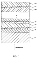
- FIG. 7- shows a structural example of a multilayer recording medium according to the present embodiment.
- the multilayer recording medium of the present embodiment includes a substrate 23, n (a natural number satisfying n ⁇ 2) sets of media 16, 18,..., 20, 22 that are laminated sequentially on the substrate 23 via separating layers 17, 19, 21, and the like.
- media 16, 18, ...,20 to the medium located at the ( n -1)th position counted from a laser-beam incident side hereinafter, the medium located at the n -th position counted from the laser-beam incident side is referred to as "the n -th medium" are formed of optical transmission type media.
- the separating layers 17, 19, 21, and the like are formed of resin such as ultraviolet curing resin or delayed action resin, dielectrics, or the like and are transparent layers with respect to a laser beam to be used.
- the k -th medium ( k is a natural number satisfying 1 ⁇ k ⁇ n ) can be recorded and reproduced through the first to the ( k -1)th media.
- Any of the first to the n- th media may be a medium exclusively used for reproduction (ROM (Read Only Memory)) or a write-once type medium.
- n 2
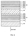
- FIG. 8 shows a structural example of a multilayer recording medium formed of two sets of media.
- this multilayer recording medium includes a substrate 100, and a first medium 101, a separating layer 109, and a second medium 201 that are laminated sequentially on the substrate 100.
- the first medium 101 includes a protective layer 102, an interface layer 103, a recording layer 104, an interface layer 105, a protective layer 106, a reflective layer 107, and a thermal diffusion layer 108 that are laminated sequentially from the substrate 100 side.
- the second medium 201 includes a protective layer 202, an interface layer 203, a recording layer 204, an interface layer 205, a protective layer 206, and a reflective layer 207 that are laminated sequentially from the separating layer 109 side.
- the same materials as described with respect to the medium shown in FIG. 1 can be used for the protective layers 102, 106, 202, and 206, the interface layers 103, 105, 203, and 205, the recording layers 104 and 204, the reflective layers 107 and 207, and the thermal diffusion layer 108.
- the separating layer 109 is provided mainly for the purpose of optically separating the first medium 101 and the second medium 201.
- the separating layer 109 is formed of a material that enables optical absorptance with respect to a laser beam used for recording and reproduction to be as low as possible.
- resin made of an organic material, such as ultraviolet curing resin and delayed action resin, a double sided adhesive sheet for an optical disk, an inorganic dielectric such as SiO 2 , Al 2 O 3 , ZnS, or the like, or a glass material can be used.
- the separating layer 109 is required to have a thickness at least equal to a focal depth ⁇ Z of a laser beam so that in recording and reproduction of one medium, crosstalk from the other medium can be suppressed to such a small degree as to be neglected.
- the thickness of the separating layer 109 is within an acceptable tolerance of the objective lens so that the distance between two media is in a range in which the objective lens can focus a laser beam.
- ⁇ r 2 ⁇ R 2 ⁇ T 1 ⁇ T 1 holds, wherein ⁇ R2 indicates the reflectance difference in the second medium 201 alone, and ⁇ r2 represents the reflectance difference in the second medium 201 in reproduction of the second medium 201 through the first medium 101.
- the optical design of the first medium 101 and the second medium 201 must be determined so that all these factors are balanced.
- a concrete example of optical designs is described as follows.
- a medium was designed so that the recording layer 104 of the first medium 101 had a reflectance R1c of 7.5% in a crystalline state and a reflectance R1a of 0.5% in an amorphous state, the recording layer 204 of the second medium 201 had a reflectance R2c of 15% in a crystalline state and a reflectance R2a of 43% in an amorphous state, and the first medium 101 had a transmittance of 50% when recording is performed only in the first medium.
- An optical design value was adjusted by varying the thickness mainly of the recording layer 104, the protective layers 102 and 106, and the reflective layer 107.
- the reflectance differences i.e. signal amplitudes in the first medium 101 and in the second medium 201 are almost equal to each other.
- Such a design can prevent tracking from being unstable due to extreme change in signal amplitudes when the medium to be recorded or reproduced is switched between the first medium 101 and the second medium 201.
- the reflectance difference is relatively small after the completion of design and therefore the signal amplitude becomes relatively small in many cases.
- the level P3 has to be set in a range in which no signal deterioration is caused by the reproduction light.
- the reproduction power levels in the first medium 101 and the second medium 201 are different from each other.
- the wavelengths of respective laser beams with which the first medium 101 and the second medium 201 are reproduced may be different, but laser beams with the same wavelength level are used in general.
- the first medium 101 has a light transmittance between 40% and 80%, further desirably between 50% and 70%.
- the signal amplitude in recording and reproducing the second medium 201 through the first medium 101 is obtained by multiplying a square of the transmittance T1 of the first medium 101. Therefore, when the first medium 101 has a light transmittance of less than 40%, the signal amplitude is less than 0.16 times, which is quite small.
- the light transmittance of the first medium 101 is very low, the quantity of light transmitted to reach the second medium 201 is decreased greatly, thus deteriorating the recording sensitivity of the second medium 201.
- the light transmittance of the first medium 101 is set to be at least 40%, further desirably at least 50%.
- the light transmittance of the first medium 101 is set to be 80% or less, further desirably 70% or less.
- FIG. 1 A method of manufacturing the above-described optical information recording medium is described using an optical information recording medium with a structure shown in FIG. 1 as an example as follows.
- Methods of manufacturing multilayer films forming the above-mentioned optical information recording medium include a sputtering method, vacuum evaporation, CVD, and the like. In this case, an example using the sputtering method is described as follows.
- FIG. 2 is a schematic view showing an example of a film-forming device.
- a vacuum pump (not shown in the figure) is connected to a vacuum container 9 via an air outlet 15, so that a high vacuum can be maintained within the vacuum container 9. Further, the vacuum container 9 is provided with a gas supply port 14, so that rare gases, nitrogen, oxygen, or mixed gases thereof can be supplied from the gas supply port 14 at a constant flow rate.
- numeral 10 indicates a substrate positioned within the vacuum container 9, and this substrate 10 is attached to a drive 11 for revolving the substrate 10 on its own axis or rotating the substrate 10.
- Numeral 12 indicates a plurality of sputter targets positioned so as to oppose the substrate 10 within the vacuum container 9. These sputter targets 12 are connected to cathodes 13, respectively.
- the cathodes 13 are connected to a DC power supply or a high-frequency power supply (not shown in the figure) via a switch not shown in the figure.
- the vacuum container 9 and the substrate 10 are maintained at a positive charge by grounding the vacuum container 9.
- a rare gas or a mixed gas of a rare gas and a very small amount of nitrogen, oxygen, or the like is used selectively depending on the case.
- the rare gas one capable of forming a film, such as Ar, Kr, or the like, may be used.
- a mixed gas of a rare gas and a very small amount of nitrogen or oxygen is used for forming the recording layer 4 and the protective layer 2, mass transfer in repeated recording of a medium can be suppressed, thus improving the repeatability.
- films with an excellent quality can be obtained by sputtering using a reactive sputtering method.
- Ge-Cr-N is used for the interface layers 3 and 5
- Ge-Cr or a material containing Ge, Cr, and O is used for targets and a mixed gas of a rare gas and nitrogen is used as a film-forming gas.
- a gas containing nitrogen atoms such as N 2 O, NO 2 , NO, N 2 , or the like, or a mixed gas of a suitable combination thereof and a rare gas may be used.
- a layer with an excellent film quality may be obtained by mixing a very small amount of oxygen into a film-forming gas as required.
- a recording/reproducing method and an erasing method in an optical information recording medium formed as described above are described as follows.
- an optical head on which a laser beam source and an objective lens are mounted a drive for leading a laser beam to a predetermined position to be irradiated, a tracking control unit and a focusing control unit for controlling positions in a track direction and a direction perpendicular to a film surface, a laser drive for modulating a laser power, and a rotation control unit for rotating the medium are used.
- Signals are recorded or erased by rotating the medium using the rotation control unit and then focusing a laser beam onto a minute spot using an optical system to irradiate the laser beam onto the medium.
- Recording marks or erased portions are formed by modulating the laser power between P1 and P2, wherein P1 indicates a power level for generating an amorphous state, which enables a local part of the recording layer 4 to be changed to an amorphous state reversibly by irradiation of the laser beam, and similarly, P2 represents a power level for generating a crystalline state, which enables a part of the recording layer 4 to be changed to a crystalline state reversibly by irradiation of the laser beam.
- P1 indicates a power level for generating an amorphous state, which enables a local part of the recording layer 4 to be changed to an amorphous state reversibly by irradiation of the laser beam
- P2 represents a power level for generating a crystalline state, which
- a reproduction power level P3 is set to be lower than both the power levels P1 and P2 described above, not to affect an optical state of a recording mark by irradiation of a laser beam at the power level, and to obtain sufficient reflectance for reproduction of recording marks from an medium by the irradiation of the laser beam.
- Signals obtained from the medium by the irradiation of the laser beam at the power level P3 are read by a detector, and thus information signals are reproduced.
- an optical information recording medium with the structure shown in FIG. 1 was formed using disk-shaped polycarbonate resin with a thickness of 0.6 mm and a diameter of 120 mm as a substrate 1, a material prepared by mixing 20 mol% of SiO 2 into ZnS for a protective layer 2, Ge 21 Sb 25 Te 54 for a recording layer 4, Ge-Cr-O-N for interface layers 3 and 5, Au for a reflective layer 6, and Al-O-N for a thermal diffusion layer 7.
- FIG. 3 shows simulation results of optical characteristics in this case.
- the recording layer 4 had a thickness of 10 nm
- the interface layers 3 and 5 had thicknesses of 10 nm and 30 nm respectively
- the reflective layer 6 had a thickness of 10 nm, which are respectively constant.
- the horizontal axis indicates the thickness (unit: ⁇ ⁇ / 64 n ) of the thermal diffusion layer 7 and shows the value obtained when the value of Ac / Aa is maximum in configurations satisfying Ra ⁇ 5% and Rc ⁇ 15%.
- the thickness of the protective layer 2 was approximately (26 to 30) ⁇ /64 n.
- FIG. 4 shows the variation in value of Ac / Aa obtained by the above-mentioned optical calculations. As can be seen from FIGs.
- the protective layer 2 had a thickness of 100nm
- the recording layer 4 a thickness of 10 nm
- the interface layers 3 and 5 thicknesses of 10 nm and 30 nm
- the reflective layer 6 a thickness of 10nm.
- the thermal diffusion layers 7 in the three media had thicknesses of 40 nm (8 ⁇ /64 n ), 60nm (12 ⁇ / 64 n ), and 80 nm (16 ⁇ / 64 n ), respectively, and these media are indicated with numerals (1), (2), and (3).
- a medium (0) having the same structure with that of the medium (1) except that no thermal diffusion layer 7 was provided was manufactured.
- the recording layer 4 and the protective layer 2 were formed by supplying a gas prepared by mixing 2.5% of nitrogen into Ar at a constant flow rate so as to obtain respective total pressures of 1.0mTorr and 0.5mTorr and applying a DC power of 1.27 W/cm 2 and a RF power of 5.10 W/cm 2 to cathodes, respectively.
- the reflective layer 6 was formed by supplying an Ar gas so as to obtain a total pressure of 3.0m Torr and applying a DC power of 4.45 W/cm 2 .
- Ge-Cr was used as a target material and a mixed gas of Ar and nitrogen as a sputter gas, and the sputter gas pressure was set to be ImTorr, the partial pressure of nitrogen to be 40% in the sputter gas, and the sputter power density to be 6.37 W/cm 2 .
- Characteristics of the disk were evaluated with respect to reflectance, a C/N ratio, and an overwriting erasing ratio.
- a (8-16) modulation mode was employed and recording was performed by using a laser beam with a wavelength of 650 nm and an objective lens with a numeral aperture of 0.60.
- the shortest bit length was 0.28 ⁇ m (that is to say, the shortest mark length is 0.41 ⁇ m) and the rotational speed of the disk was set so as to obtain a linear velocity of 8.2 m/s.
- a substrate 1 a substrate with a track pitch of 1.20 ⁇ m, i.e. a substrate in which groove portions and land portions were formed alternately every 0.60 ⁇ m, was used.
- the C/N ratio was evaluated by recording a mark with a length of 3T (hereinafter referred to as a "3T mark") in the (8 -16) modulation mode and measuring the C/N ratio.
- the erasing characteristics were evaluated by recording a 3T mark in the (8 - 16) modulation mode at an appropriate laser power, then overwriting it with a mark having a length of 11T (hereinafter referred to as a "11T mark”), and measuring the erasing ratio of the 3T mark (hereinafter referred to as a "3T erasing ratio”) and the erasing ratio of the 11T mark (hereinafter referred to as a "11T erasing ratio”) when a 11T mark was overwritten with a 3T mark.
- Table 1 shows the evaluation results of the media (0) to (3).
- Table 1 Medium Number Reflectance (%) Transmittance (%) C/N Ratio (dB) 3T Erasing Ratio (-dB) 11T Erasing Ratio (-dB) Rc Ra Tc Ta (0) 16.1 4.7 20.0 40.0 52.0 30 33 (1) 16.2 4.5 24.5 48.0 54.5 33 36 (2) 16.8 4.4 23.8 48.0 55.0 33 35 (3) 17.1 4.2 21.0 45.0 55.0 32 34
- the measurement of the transmittance of the media was performed by manufacturing disks with completely the same structures as those of the media (0) to (3) on mirror substrates and measuring transmittance of these disks using a spectroscope. As can be seen from Table 1, any transmittance obtained in the media (1) to (3) with thermal diffusion layers is higher than that in the medium (0) having no thermal diffusion layer.
- FIGs. 5 and 6 show simulation results of the optical characteristics.
- a recording layer 4 had a thickness of 10 nm, interface layers 3 and 5 thicknesses of 20 nm and 35 nm respectively, and a reflective layer 6 a thickness of 15nm.
- the thickness dof the thermal diffusion layer 7 (Si) satisfies 0 ⁇ d ⁇ 12 ⁇ / 64 n
- the value of Ac / Aa is increased at approximately the same Rc and Ra compared to the case where no thermal diffusion layer 7 (Si) is provided.
- a medium (4) was manufactured with the same structure as that of the medium (1) except for a protective layer 2 with a thickness of 120 nm, interface layers 3 and 5 made of Cr-Al-O-N with thicknesses of 20 nm and 35 nm, a reflective layer 6 formed ofAu with a thickness of 15 nm, and a thermal diffusion layer 7 made of Si with a thickness of 30nm(8 ⁇ /64 n ).
- a medium (0)' was manufactured with the same structure as that of the medium (4) except that no thermal diffusion layer 7 was provided.
- Table 2 shows the same evaluation results with respect to the media (4) and (0)' as those with respect to the media (0) to (3).
- Table 2 Medium Number Reflectance (%) C/N Ratio (dB) 3T Erasing Ratio (-dB) 11T Erasing Ratio (-dB) Rc Ra (0)' 15.1 1.2 52.4 30 32 (4) 16.5 1.4 54.3 33 35
- an optical information recording medium with the structure shown in FIG. 8 was manufactured using disk-shaped polycarbonate resin with a thickness of 0.6 mm and a diameter of 120 mm as a substrate 100, a material obtained by mixing 20 mol% of SiO 2 into ZnS for protective layers 102, 106, 202, and 206, Ge-Cr-N for interface layers 103, 105, 203, and 205, a AgPdCu alloy for reflective layers 107 and 207, TiO 2 for a thermal diffusion layer 108, and Ge 4 Sb 2 Te 7 for recording layers 104 and 204.
- the recording layers 104 and 204 have thicknesses of 6 nm and 9 nm, all the interface layers 103, 105, 203, and 205 a thickness of 2nm, the reflective layers 107 and 207 thicknesses of 10 nm and 80 nm, the thermal diffusion layer 108 a thickness of 40 nm, the protective layers 102 and 106 thicknesses of 110 nm and 34 nm, and the protective layers 202 and 206 thicknesses of 90 nm and 40 nm, respectively.
- the respective layers are formed under the same conditions as those in the above-described first embodiment.
- Characteristics of the disk were evaluated by measuring a C/N ratio, an overwriting erasing ratio and cycling characteristics with respect to both a first medium 101 and a second medium 201.
- a (8 - 16) modulation mode was employed and recording and reproduction were performed with respect to the first medium 101 and the second medium 201 by using a laser beam with a wavelength of 405 nm and an objective lens with a numeral aperture of 0.65.
- the shortest mark length was 0.26 ⁇ m and the rotational speed of the disk was set so as to obtain a linear velocity of 8.2 m/s.
- the C/N ratio was evaluated by recording a mark with a length of 3T (hereinafter referred to as a "3T mark”) ten times at an appropriate laser beam power in the (8 - 16) modulation mode and measuring the C/N ratios.
- the overwriting erasing characteristics were evaluated by recording a 3T mark nine times at an appropriate laser power in the (8 - 16) modulation mode, then overwriting the 3T mark with a mark having a length of 11T (hereinafter referred to as a "11T mark”) once at the same power, and measuring the erasing ratio of the 3T mark (hereinafter referred to as a "3T erasing ratio").
- the cycling characteristics evaluation was performed by evaluating how much the jitter value was decreased when random signals were recorded as the number of recording times increased.
- the power used for the reproduction of signals was set to be 1.0 mW with respect to both the first medium 101 and the second medium 201.
- the recording and reproduction of the second medium 201 were performed under the condition in which signals were not recorded in the first medium 101 for convenience.
- the two-layer recording medium described above is referred to as a medium (5).
- a two-layer recording medium (6) was manufactured with the same structure as that of the medium (5) except that no thermal diffusion layer 108 was provided.
- Table 3 shows evaluation results with respect to the media (5) and (6).
- Table 3 Medium Number Thermal Diffusion Layer C/N Ratio Erasing Ratio Cycling Characteristics L1 L2 L1 L2 L1 L2 (5) TiO 2 ⁇ ⁇ ⁇ ⁇ ⁇ (6) None ⁇ ⁇ ⁇ ⁇ ⁇ ⁇ ⁇ ⁇
- L1 indicates the first medium 101 and L2 represents the second medium 201.
- the case where at least 50 dB was obtained is indicated by ⁇ and the case where less than 50dB was obtained is indicated by ⁇ .
- the case where a 3T erasing ratio of at least 33 dB was obtained is indicated by ⁇ and the case where a 3T erasing ratio of less than 33dB was obtained is indicated by ⁇ .
- the reason can be described as follows.
- a value of optical absorptive correction (a value of Ac / Aa ) between a crystalline state and an amorphous state as described above. Therefore, the erasing ratio is low and the C/N ratio of a 3T signal after 10-times overwriting recording also is decreased in the medium (6).
- the medium (5) having the thermal diffusion layer 108 not only a high C/N ratio and a high erasing ratio but also high light transmittance can be obtained at the same time with respect to the first medium 101 (L1). Thus, excellent characteristics of the second medium 201 (L2) also can be obtained.
- the thermal diffusion layer 108 has an effect for improving the cycling characteristics. It is conceivable that the cooling power that has been deteriorated by employing the thin reflective layer was compensated by the thermal diffusion layer 108 and the thermal load on the medium in repeated recording was decreased in the medium (5).
- two-layer recording media (7) to (10) were manufactured using the same structure as that of the medium (5) except for the thermal diffusion layers 108 that are formed of Ti-N, Ta 2 O 5 , Si-N, and Zr-N, respectively.
- the same evaluations were performed with respect to the media (7) to (10) and the same excellent characteristics as those in the medium (5) were obtained.
- the thermal diffusion layers 108 were provided, the compatibility between high transmittance and high absorptive correction was obtained and the cycling characteristics were improved greatly.
- an optical information recording medium is provided with a recording layer whose optical characteristics are varied reversibly by irradiation of a laser beam, a reflective layer that transmits the laser beam with a wavelength ⁇ , and a thermal diffusion layer provided while being in contact with the reflective layer.
- a thickness dof the thermal diffusion layer was set to be within a range of 0 ⁇ d ⁇ (5/16) ⁇ / n or (7/16) ⁇ / n ⁇ d ⁇ (1/2) ⁇ / n, wherein n indicates a refractive index of the thermal diffusion layer.
- the cooling power of the recording layer can be further improved and at the same time overwriting distortion can be decreased by the increase in value of Ac / Aa.
- recording can be performed at higher speed with higher density.
- the C/N ratio of a recording signal can be increased. Further, since the thermal load on the medium can be decreased, repeated recording characteristics also can be improved.
Landscapes
- Chemical & Material Sciences (AREA)
- Inorganic Chemistry (AREA)
- Optical Record Carriers And Manufacture Thereof (AREA)
- Thermal Transfer Or Thermal Recording In General (AREA)
Claims (13)
- Optisches Informationsaufzeichnungsmedium mit:einer Aufzeichnungsschicht (4), deren optische Kennwerte durch Bestrahlung mit einem Laserstrahl reversibel variiert werden;einer reflektierenden Schicht (6), die einen Laserstrahl mit einer Wellenlänge λ, durchläßt; undeiner Thermodiffusionsschicht (7), die in Kontakt mit der reflektierenden Schicht vorgesehen ist,
wobei eine Dicke d der Thermodiffusionsschicht (7) in einem Bereich von 0 < d ≤ (5/16)λ/n oder (7/16)λ/n ≤ d ≤ (1/2) λ/n liegt, wobei n eine Brechzahl der Thermodiffusionsschicht bezeichnet,
dadurch gekennzeichnet, daß die reflektierende Schicht (6) zwischen der Thermodiffusionsschicht (7) und der Aufzeichnungsschicht (4) liegt. - Optisches Informationsaufzeichnungsmedium nach Anspruch 1,
wobei die Wärmeleitfähigkeit eines die Thermodiffusionsschicht (7) bildenden Materials mindestens 0,05 W/m·K bei 500 K beträgt. - Optisches Informationsaufzeichnungsmedium nach Anspruch 1 oder 2,
wobei die Brechzahl der Thermodiffusionsschicht (7) mindestens 1,6 für eine zur Aufzeichnung und Wiedergabe von Informationen verwendete Wellenlänge des Laserstrahls beträgt. - Optisches Informationsaufzeichnungsmedium nach Anspruch 1, 2 oder 3,
wobei der Absorptionskoeffizient der Thermodiffusionsschicht (7) höchstens 1,5 für eine zur Aufzeichnung und Wiedergabe von Informationen verwendete Wellenlänge des Laserstrahls beträgt. - Optisches Informationsaufzeichnungsmedium nach Anspruch 1, 2, 3 oder 4,
wobei die Thermodiffusionsschicht (7) mindestens eine Komponente enthält, die aus einer Gruppe ausgewählt ist, die aus Al-N, Al-O-N, Al-C, Si, Si-N, SiO2, Si-O-N, Si-C, Ti-N, TiO2, Ti-C, Ta-N, Ta2O5, Ta-O-N, Ta-C, Zn-O, ZnS, ZnSe, Zr-N, Zr-O-N, Zr-C und W-C besteht. - Medium nach einem der Ansprüche 1 bis 5,
wobei die reflektierende Schicht (6) mindestens eine Komponente enthält, die aus einer Gruppe ausgewählt ist, die aus Au, Ag und Cu besteht. - Medium nach einem der Ansprüche 1 bis 6,
wobei die reflektierende Schicht (6) eine Dicke zwischen 1 nm und 20 nm hat. - Medium nach einem der Ansprüche 1 bis 6,
wobei die Aufzeichnungsschicht (4) eine Dicke zwischen 3 nm und 20 nm hat. - Medium nach einem der Ansprüche 1 bis 8,
wobei die Aufzeichnungsschicht (4) aus einem Phasenänderungsmaterial gebildet ist, das mindestens eine Komponente enthält, die aus einer Gruppe ausgewählt ist, die aus Te, Se und Sb besteht. - Medium nach einem der Ansprüche 1 bis 9,
wobei das optische Informationsaufzeichnungsmedium für den Laserstrahl einen mittleren Lichtdurchlaßgrad zwischen 40 % und 80 % hat. - Optisches Informationsaufzeichnungsmedium nach Anspruch 10,
wobei mindestens ein anderes optisches Informationsaufzeichnungsmedium auf der der Einfallsseite des Laserstrahls gegenüberliegenden Seite vorgesehen ist. - Medium nach einem der Ansprüche 1 bis 11,
wobei das optische Informationsaufzeichnungsmedium ferner eine Grenzflächenschicht (3, 5) aufweist, die eine Wirkung zur Erleichterung der Kristallisation der Aufzeichnungsschicht (4) hat und die in Kontakt mit mindestens einer Seite der Aufzeichnungsschicht (4) steht. - Optisches Informationsaufzeichnungsmedium nach Anspruch 12,
wobei die Grenzflächenschicht (3, 5) aus einem Material gebildet ist, das mindestens N enthält.
Applications Claiming Priority (2)
| Application Number | Priority Date | Filing Date | Title |
|---|---|---|---|
| JP33463798 | 1998-11-25 | ||
| JP33463798 | 1998-11-25 |
Publications (2)
| Publication Number | Publication Date |
|---|---|
| EP1005036A1 EP1005036A1 (de) | 2000-05-31 |
| EP1005036B1 true EP1005036B1 (de) | 2006-02-08 |
Family
ID=18279610
Family Applications (1)
| Application Number | Title | Priority Date | Filing Date |
|---|---|---|---|
| EP99123167A Expired - Lifetime EP1005036B1 (de) | 1998-11-25 | 1999-11-23 | Optisches Informationsaufzeichnungsmedium |
Country Status (5)
| Country | Link |
|---|---|
| US (1) | US6449239B1 (de) |
| EP (1) | EP1005036B1 (de) |
| KR (1) | KR100372181B1 (de) |
| CN (1) | CN1174399C (de) |
| DE (1) | DE69929739T2 (de) |
Families Citing this family (30)
| Publication number | Priority date | Publication date | Assignee | Title |
|---|---|---|---|---|
| JP2001023245A (ja) * | 1999-07-09 | 2001-01-26 | Sony Corp | 光記録媒体および光記録装置 |
| KR100455853B1 (ko) | 1999-12-21 | 2004-11-06 | 마쯔시다덴기산교 가부시키가이샤 | 광학 정보 기록매체와 그 기록 재생 방법 및 이것을이용한 광학 정보의 기록 재생 시스템 |
| JP4269471B2 (ja) * | 2000-02-21 | 2009-05-27 | ソニー株式会社 | 光記録媒体、光ピックアップおよび光記録再生装置 |
| KR100458299B1 (ko) * | 2000-10-10 | 2004-11-26 | 티디케이가부시기가이샤 | 광기록방법 및 광기록매체 |
| US6734455B2 (en) * | 2001-03-15 | 2004-05-11 | Micron Technology, Inc. | Agglomeration elimination for metal sputter deposition of chalcogenides |
| JP4814476B2 (ja) * | 2001-04-20 | 2011-11-16 | Tdk株式会社 | 光情報媒体の再生方法 |
| CN1734608A (zh) * | 2001-09-12 | 2006-02-15 | 松下电器产业株式会社 | 光学信息记录媒体 |
| JP4166455B2 (ja) * | 2001-10-01 | 2008-10-15 | 株式会社半導体エネルギー研究所 | 偏光フィルム及び発光装置 |
| JP4024510B2 (ja) * | 2001-10-10 | 2007-12-19 | 株式会社半導体エネルギー研究所 | 記録媒体、および基材 |
| TWI254301B (en) * | 2002-04-05 | 2006-05-01 | Tdk Corp | Optical recording medium and method for optically recording information in the same |
| TWI254934B (en) | 2002-04-26 | 2006-05-11 | Tdk Corp | Optical recording medium and method for optically recording data in the same |
| JP2004030843A (ja) * | 2002-06-28 | 2004-01-29 | Pioneer Electronic Corp | 情報記録再生媒体 |
| US20040038080A1 (en) * | 2002-07-01 | 2004-02-26 | Tdk Corporation | Optical recording medium and method for recording data in the same |
| JP4092147B2 (ja) * | 2002-07-04 | 2008-05-28 | Tdk株式会社 | 光記録媒体及び光記録方法 |
| JP4282285B2 (ja) * | 2002-08-12 | 2009-06-17 | Tdk株式会社 | 光記録媒体及び光記録方法 |
| US20040076907A1 (en) * | 2002-10-22 | 2004-04-22 | Tdk Corporation | Optical recording medium and method for manufacturing the same |
| US7781146B2 (en) * | 2002-11-22 | 2010-08-24 | Tdk Corporation | Optical recording medium |
| AU2003289318A1 (en) * | 2002-12-13 | 2004-07-09 | Matsushita Electric Industrial Co., Ltd. | Optical information recording medium and method for manufacturing same |
| US7932015B2 (en) | 2003-01-08 | 2011-04-26 | Tdk Corporation | Optical recording medium |
| JP2005071402A (ja) * | 2003-08-25 | 2005-03-17 | Tdk Corp | 光情報記録媒体 |
| JP2005122872A (ja) * | 2003-09-22 | 2005-05-12 | Ricoh Co Ltd | 2層相変化型情報記録媒体及びその記録再生方法 |
| US7858290B2 (en) * | 2003-10-02 | 2010-12-28 | Panasonic Corporation | Information recording medium and method for manufacturing the same |
| JP4064905B2 (ja) * | 2003-10-29 | 2008-03-19 | 株式会社東芝 | 相変化光記録媒体 |
| JP2005251279A (ja) * | 2004-03-03 | 2005-09-15 | Nec Corp | 光学的情報記録媒体及びその製造方法 |
| WO2005091282A1 (en) * | 2004-03-18 | 2005-09-29 | Ricoh Company, Ltd. | Optical recording medium and two layered optical recording medium, recording and reproducing method and recording and reproducing apparatus using media |
| TW200601322A (en) * | 2004-04-07 | 2006-01-01 | Hitachi Maxell | Information recording medium |
| JP4227091B2 (ja) * | 2004-10-01 | 2009-02-18 | 株式会社東芝 | 相変化光記録媒体 |
| US20060114791A1 (en) * | 2004-11-30 | 2006-06-01 | Charles Marshall | Ultra-high data density optical media system |
| JP4193147B2 (ja) * | 2005-09-29 | 2008-12-10 | 日本電気株式会社 | 光学的情報記録媒体及びその製造方法 |
| US20070154674A1 (en) * | 2005-12-29 | 2007-07-05 | Imation Corp. | Recordable optical media with thermal buffer layer |
Family Cites Families (14)
| Publication number | Priority date | Publication date | Assignee | Title |
|---|---|---|---|---|
| EP0368194B1 (de) * | 1988-11-07 | 1998-06-17 | Hitachi, Ltd. | Magneto-optisches Speichermedium |
| JP3038853B2 (ja) * | 1990-09-13 | 2000-05-08 | 株式会社ニコン | 高レベルのマージンが拡大したオーバーライト可能な光磁気記録媒体 |
| EP0566107B1 (de) * | 1992-04-17 | 1998-03-18 | Matsushita Electric Industrial Co., Ltd. | Optisches Informationsaufzeichnungsmedium und Verfahren zum Entwurf seiner Struktur |
| EP0569664B1 (de) | 1992-05-15 | 1999-05-19 | Ricoh Company, Ltd | Optisches Informationsaufzeichnungsmedium und es verwendendes Aufzeichnungsverfahren |
| CN1083615A (zh) * | 1992-08-19 | 1994-03-09 | 菲利浦电子有限公司 | 信息存储系统 |
| JP3313246B2 (ja) | 1994-08-08 | 2002-08-12 | 松下電器産業株式会社 | 光学的情報記録媒体 |
| JP3516996B2 (ja) * | 1994-09-21 | 2004-04-05 | 株式会社東芝 | 情報記録媒体およびその製造方法 |
| JPH08129777A (ja) | 1994-11-02 | 1996-05-21 | Matsushita Electric Ind Co Ltd | 光学的情報記録媒体 |
| JP2785763B2 (ja) | 1995-09-27 | 1998-08-13 | 日本電気株式会社 | 相変化光ディスク |
| TW336317B (en) | 1996-02-28 | 1998-07-11 | Asahi Chemical Ind | Design method of phase change type recording medium and the phase change optical recording medium |
| JPH09270156A (ja) * | 1996-04-01 | 1997-10-14 | Canon Inc | 光磁気記録媒体 |
| TW414892B (en) | 1996-05-28 | 2000-12-11 | Ibm | Optical data storage system with multiple rewriteable phase-change recording layers |
| JP3738523B2 (ja) * | 1997-04-09 | 2006-01-25 | 株式会社ニコン | 記録可能な光ディスク |
| US6017620A (en) * | 1997-04-10 | 2000-01-25 | Tdk Corporation | Magneto-optical recording medium |
-
1999
- 1999-11-18 US US09/442,900 patent/US6449239B1/en not_active Expired - Lifetime
- 1999-11-23 DE DE69929739T patent/DE69929739T2/de not_active Expired - Lifetime
- 1999-11-23 EP EP99123167A patent/EP1005036B1/de not_active Expired - Lifetime
- 1999-11-25 KR KR10-1999-0052715A patent/KR100372181B1/ko not_active Expired - Fee Related
- 1999-11-25 CN CNB991248953A patent/CN1174399C/zh not_active Expired - Lifetime
Also Published As
| Publication number | Publication date |
|---|---|
| CN1254914A (zh) | 2000-05-31 |
| CN1174399C (zh) | 2004-11-03 |
| KR20000035689A (ko) | 2000-06-26 |
| DE69929739T2 (de) | 2006-08-10 |
| US6449239B1 (en) | 2002-09-10 |
| DE69929739D1 (de) | 2006-04-20 |
| EP1005036A1 (de) | 2000-05-31 |
| KR100372181B1 (ko) | 2003-02-14 |
Similar Documents
| Publication | Publication Date | Title |
|---|---|---|
| EP1005036B1 (de) | Optisches Informationsaufzeichnungsmedium | |
| EP0978831B1 (de) | Optisches Aufzeichnungsmedium und Verfahren zu seiner Herstellung, Verfahren zur Informationsaufzeichnung und -wiedergabe darauf, und Aufzeichnungs-/Wiedergabegerät | |
| EP1347448B1 (de) | Optisches Aufzeichnungsmedium und zugehöriges Aufzeichnungsverfahren | |
| EP0945860B1 (de) | Optisches Informationsaufzeichnungsmedium und Verfahren zur Aufzeichnung und Wiedergabe von optischen Informationen | |
| EP1189216B1 (de) | Optisches aufzeichnungsmedium, verfahren zur aufzeichnung und wiedergabe, und optisches aufzeichnungs- und -wiedergabesystem | |
| EP1349160B1 (de) | Optisches Informationsaufzeichnungsmedium und Verfahren zur dessen Herstellung | |
| JP2000298875A (ja) | 光記録媒体 | |
| EP1542217B1 (de) | Optisches informationsaufzeichnungsmedium und herstellungsverfahren dafür | |
| EP1102252B1 (de) | Optisches Phasenwechselaufzeichnungsmedium mit Kristallkeimbildungsschicht | |
| EP1609615A1 (de) | Datenaufzeichnungsmedium und verfahren zu dessen herstellung | |
| EP1345218B1 (de) | Medium für optische Datenspeicherung sowie dessen Herstellungsverfahren, und Aufzeichnungs- sowie Reproduktionsverfahren unter Benutzung dieses Mediums | |
| JP2000222777A (ja) | 光学情報記録媒体 | |
| EP1548721B1 (de) | Optisches aufzeichnungsmedium | |
| EP1575042B1 (de) | Optisches Informationsaufzeichnungsmedium, Herstellungsverfahren, Aufzeichnungsverfahren und Aufzeichnungsvorrichtung dafür | |
| KR20010022958A (ko) | 재기록가능한 광 정보매체 | |
| EP1523001B1 (de) | Optischer Datenträger und Verfahren zur Herstellung desselben | |
| JP4124535B2 (ja) | 光学情報記録媒体およびその記録再生方法 | |
| EP1630801A1 (de) | Optisches informationsaufzeichnungsmedium und prozess zu seiner herstellung | |
| JP2004005920A (ja) | 相変化型情報記録媒体 | |
| JP2004318917A (ja) | 光記録媒体 | |
| JP2004079151A (ja) | 相変化型情報記録媒体 | |
| EP1524656B1 (de) | Medium zur optischen Datenspeicherung und Verfahren zu dessen Herstellung | |
| JP4214155B2 (ja) | 光学情報記録媒体及びその記録再生方法 | |
| JP2004005938A (ja) | 2層構成型光記録媒体 | |
| JP2004030877A (ja) | 2層構成型光記録媒体 |
Legal Events
| Date | Code | Title | Description |
|---|---|---|---|
| PUAI | Public reference made under article 153(3) epc to a published international application that has entered the european phase |
Free format text: ORIGINAL CODE: 0009012 |
|
| AK | Designated contracting states |
Kind code of ref document: A1 Designated state(s): DE FR GB NL |
|
| AX | Request for extension of the european patent |
Free format text: AL;LT;LV;MK;RO;SI |
|
| 17P | Request for examination filed |
Effective date: 20000425 |
|
| AKX | Designation fees paid |
Free format text: DE FR GB NL |
|
| 17Q | First examination report despatched |
Effective date: 20041206 |
|
| GRAP | Despatch of communication of intention to grant a patent |
Free format text: ORIGINAL CODE: EPIDOSNIGR1 |
|
| GRAS | Grant fee paid |
Free format text: ORIGINAL CODE: EPIDOSNIGR3 |
|
| GRAA | (expected) grant |
Free format text: ORIGINAL CODE: 0009210 |
|
| AK | Designated contracting states |
Kind code of ref document: B1 Designated state(s): DE FR GB NL |
|
| REG | Reference to a national code |
Ref country code: GB Ref legal event code: FG4D |
|
| REF | Corresponds to: |
Ref document number: 69929739 Country of ref document: DE Date of ref document: 20060420 Kind code of ref document: P |
|
| ET | Fr: translation filed | ||
| PLBE | No opposition filed within time limit |
Free format text: ORIGINAL CODE: 0009261 |
|
| STAA | Information on the status of an ep patent application or granted ep patent |
Free format text: STATUS: NO OPPOSITION FILED WITHIN TIME LIMIT |
|
| 26N | No opposition filed |
Effective date: 20061109 |
|
| REG | Reference to a national code |
Ref country code: FR Ref legal event code: PLFP Year of fee payment: 17 |
|
| REG | Reference to a national code |
Ref country code: FR Ref legal event code: PLFP Year of fee payment: 18 |
|
| REG | Reference to a national code |
Ref country code: FR Ref legal event code: PLFP Year of fee payment: 19 |
|
| PGFP | Annual fee paid to national office [announced via postgrant information from national office to epo] |
Ref country code: FR Payment date: 20171012 Year of fee payment: 19 |
|
| PGFP | Annual fee paid to national office [announced via postgrant information from national office to epo] |
Ref country code: GB Payment date: 20171122 Year of fee payment: 19 Ref country code: NL Payment date: 20171016 Year of fee payment: 19 |
|
| PGFP | Annual fee paid to national office [announced via postgrant information from national office to epo] |
Ref country code: DE Payment date: 20181113 Year of fee payment: 20 |
|
| REG | Reference to a national code |
Ref country code: NL Ref legal event code: MM Effective date: 20181201 |
|
| GBPC | Gb: european patent ceased through non-payment of renewal fee |
Effective date: 20181123 |
|
| PG25 | Lapsed in a contracting state [announced via postgrant information from national office to epo] |
Ref country code: NL Free format text: LAPSE BECAUSE OF NON-PAYMENT OF DUE FEES Effective date: 20181201 |
|
| PG25 | Lapsed in a contracting state [announced via postgrant information from national office to epo] |
Ref country code: FR Free format text: LAPSE BECAUSE OF NON-PAYMENT OF DUE FEES Effective date: 20181130 |
|
| REG | Reference to a national code |
Ref country code: DE Ref legal event code: R071 Ref document number: 69929739 Country of ref document: DE |
|
| PG25 | Lapsed in a contracting state [announced via postgrant information from national office to epo] |
Ref country code: GB Free format text: LAPSE BECAUSE OF NON-PAYMENT OF DUE FEES Effective date: 20181123 |