EP1005108A2 - Universelle Erdungsklemmezusammenbau - Google Patents
Universelle Erdungsklemmezusammenbau Download PDFInfo
- Publication number
- EP1005108A2 EP1005108A2 EP99309452A EP99309452A EP1005108A2 EP 1005108 A2 EP1005108 A2 EP 1005108A2 EP 99309452 A EP99309452 A EP 99309452A EP 99309452 A EP99309452 A EP 99309452A EP 1005108 A2 EP1005108 A2 EP 1005108A2
- Authority
- EP
- European Patent Office
- Prior art keywords
- messenger
- clip
- interchangeable
- strand
- ground
- Prior art date
- Legal status (The legal status is an assumption and is not a legal conclusion. Google has not performed a legal analysis and makes no representation as to the accuracy of the status listed.)
- Withdrawn
Links
Images


Classifications
-
- H—ELECTRICITY
- H01—ELECTRIC ELEMENTS
- H01R—ELECTRICALLY-CONDUCTIVE CONNECTIONS; STRUCTURAL ASSOCIATIONS OF A PLURALITY OF MUTUALLY-INSULATED ELECTRICAL CONNECTING ELEMENTS; COUPLING DEVICES; CURRENT COLLECTORS
- H01R4/00—Electrically-conductive connections between two or more conductive members in direct contact, i.e. touching one another; Means for effecting or maintaining such contact; Electrically-conductive connections having two or more spaced connecting locations for conductors and using contact members penetrating insulation
- H01R4/58—Electrically-conductive connections between two or more conductive members in direct contact, i.e. touching one another; Means for effecting or maintaining such contact; Electrically-conductive connections having two or more spaced connecting locations for conductors and using contact members penetrating insulation characterised by the form or material of the contacting members
- H01R4/64—Connections between or with conductive parts having primarily a non-electric function, e.g. frame, casing, rail
- H01R4/646—Connections between or with conductive parts having primarily a non-electric function, e.g. frame, casing, rail for cables or flexible cylindrical bodies
-
- H—ELECTRICITY
- H01—ELECTRIC ELEMENTS
- H01R—ELECTRICALLY-CONDUCTIVE CONNECTIONS; STRUCTURAL ASSOCIATIONS OF A PLURALITY OF MUTUALLY-INSULATED ELECTRICAL CONNECTING ELEMENTS; COUPLING DEVICES; CURRENT COLLECTORS
- H01R4/00—Electrically-conductive connections between two or more conductive members in direct contact, i.e. touching one another; Means for effecting or maintaining such contact; Electrically-conductive connections having two or more spaced connecting locations for conductors and using contact members penetrating insulation
- H01R4/24—Connections using contact members penetrating or cutting insulation or cable strands
- H01R4/2404—Connections using contact members penetrating or cutting insulation or cable strands the contact members having teeth, prongs, pins or needles penetrating the insulation
- H01R4/2408—Connections using contact members penetrating or cutting insulation or cable strands the contact members having teeth, prongs, pins or needles penetrating the insulation actuated by clamping screws
Definitions
- the present invention relates generally to devices and methods for implementing a ground connection between a conductor of a cable messenger strand and a cable clamp.
- the present invention is directed to a universal ground clip assembly comprising a unique ground clip that may be utilized with interchangeable messenger clamps which have jaws that are typically clamped over the insulation jacket of the cable messenger strand.
- the present invention also pertains to the method of installing the universal ground clip assembly.
- a multitude of approaches have been taken to address the problem of grounding a cable clamp to a cable messenger strand.
- Some approaches involve stripping the insulation from the messenger strand to effect a ground connection using conventional grounding techniques. For instance, once the insulation has been removed, a cable clamp is positioned around the strand, a ground wire is positioned in contact with the messenger strand conductor between the conductor and the strand, and the clamp is secured to the strand thus effecting the ground connection.
- Such conventional techniques are time consuming.
- stripping of the insulation may be hazardous to personnel and can adversely affect the integrity of the cable and strand.
- the present invention addresses the above needs by providing a universal ground clip assembly whose primary object or purpose is to electrically connect interchangeable messenger clamps to a cable messenger strand strung between utility poles.
- the messenger strand typically includes an insulation jacket for insulating a conductor.
- the ground clip assembly comprises a grounding clip positioned over the insulation jacket of the messenger strand.
- the grounding clip includes a penetration means for penetrating the messenger strand insulation jacket and engaging the messenger strand conductor wherein compression of the grounding clip on the messenger strand causes the penetration means to penetrate the insulation jacket thereby establishing an electrical connection with the messenger strand conductor.
- this embodiment of the clip assembly includes a variety of interchangeable messenger damp means, such as a ground or span clamp, capable of engaging the grounding clip.
- the interchangeable messenger clamp means Upon engagement, the interchangeable messenger clamp means establishes an electrical connection with the grounding clip.
- the interchangeable messenger clamp means may further include a ground connection means for electrically connecting the interchangeable messenger clamp means to a ground.
- the grounding clip is preferably positioned and compressed on the messenger strand prior to installation of the interchangeable messenger clamp means.
- the grounding clip preferably comprises a saddle clip having a generally U-shaped cross-section with opposing first and second side members.
- the penetration means may either comprise a pointed prong formed in at least one of the first and second side members or at least one pointed prong formed in each of the first and second side members.
- the present invention also addresses the above needs in another embodiment by providing a universal ground clip whose primary object or purpose is to establish electrical connection with a cable messenger strand strung between utility poles.
- the messenger strand typically includes an insulation jacket for insulating a conductor.
- the ground clip comprises a generally U-shaped saddle body having opposing first and second side members and a length sufficient to accommodate a variety of interchangeable messenger clamp means.
- the saddle body positioned over the insulation jacket of the messenger strand.
- the clip further includes a penetration means for penetrating the messenger strand insulation jacket and engaging the messenger strand conductor. Compression of the saddle body on the messenger strand causes the penetration means to penetrate the insulation jacket thereby establishing an electrical connection with the messenger strand conductor.
- the saddle body is positioned and compressed on the messenger strand prior to installation of the interchangeable clamp means while the penetration means comprises a pointed prong formed in at least one of the first and second side members or at least one pointed prong formed in each of the first and second side members.
- the present invention addresses the above needs in another embodiment by providing a method for electrically connecting interchangeable messenger clamps to a cable messenger strand strung between utility poles wherein the messenger strand includes an insulation jacket for insulating a conductor.
- the method comprises the steps of: (a) forming a grounding clip out of sheet metal; (b) further fashioning the grounding clip to include a penetration means for penetrating the messenger strand insulation jacket and engaging the messenger strand conductor; (c) positioning the grounding clip over the insulation jacket of the messenger strand; (d) compressing the grounding clip so as to cause the penetration means to penetrate the insulation jacket thereby establishing an electrical connection with the messenger strand conductor; and (e) selectively attaching interchangeable messenger clamp means to the grounding clip thereby establishing an electrical connection with the grounding clip.
- the step of compressing the grounding clip is accomplished using a conventional hand tool, such as a pair of plyers, and occurs prior to the step of selectively attaching interchangeable messenger clamp means.
- the interchangeable messenger damp means preferably comprises a ground or span clamp and may further include a ground connection means for electrically connecting the interchangeable messenger clamp means to a ground.
- the grounding clip preferably comprises a saddle clip having a generally U-shaped cross-section with first and second side members.
- the penetration means may either comprise a pointed prong formed in at least one of the first and second side members or at least one pointed prong formed in each of the first and second side members.
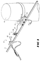
- clip assembly 10 is preferably utilized in the aerial installation of a conventional cable messenger strand 11 or the like that is strung between utility poles 12.
- one purpose of clip assembly 10 is to electrically connect a variety of conventional interchangeable messenger clamps, denoted as 13a, 13b, 13c, 13d throughout the figures, to the messenger strand 11.
- the messenger strand 11 typically includes an insulation jacket 14 for insulating a conductor 16.
- a grounding clip 17 formed from sheet metal is positioned over the insulation jacket 14 of the messenger strand 11.
- the grounding clip 17 includes a penetration means for penetrating the messenger strand insulation jacket 14 and engaging the messenger strand conductor 16 wherein compression of the grounding clip 17 on the messenger strand 11 causes the penetration means to penetrate the insulation jacket 14 thereby establishing an electrical connection with the messenger strand conductor 16. Compression of the grounding clip 17 is preferably accomplished through the use of a conventional hand tool 18, such as plyers.
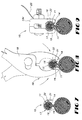
- the grounding clip 17 preferably comprises a saddle clip having a generally U-shaped cross-section with opposing first 19 and second 21 side members and a length sufficient to accommodate a variety of interchangeable messenger clamp means.
- the penetration means may either comprise a pointed prong 22 formed in at least one of the first 19 and second 21 side members or at least one pointed prong 22 formed in each of the first 19 and second 21 side members.
- the clip assembly 10 may further include the variety of interchangeable messenger clamp means, such as a ground clamp 13b, 13d, span clamp 13a, or any other type 13c of clamp for messenger strands, capable of engaging the grounding clip 17.
- the interchangeable messenger clamp means Upon engagement, the interchangeable messenger clamp means establishes an electrical connection with the grounding clip 17.
- the interchangeable messenger clamp means may further include a ground connection means, such as a ground wire 23, for electrically connecting the interchangeable messenger clamp means to a ground (not shown).
- the grounding clip 17 is preferably positioned and compressed on the messenger strand 11 prior to installation of the interchangeable messenger clamp means 13a-d.
- Figures 7-9 illustrate a method for electrically connecting interchangeable messenger clamps 13a-d to the cable messenger strand 11 strung between utility poles.
- the method comprises the steps of: (a) forming a grounding clip 17 out of sheet metal; (b) further fashioning the grounding clip to include a penetration means 22 for penetrating the messenger strand insulation jacket 14 and engaging the messenger strand conductor 16; (c) positioning the grounding clip 17 over the insulation jacket 14 of the messenger strand 11; (d) compressing the grounding clip 17 so as to cause the penetration means 22 to penetrate the insulation jacket 14 thereby establishing an electrical connection with the messenger strand conductor 16 ; and (e) selectively attaching interchangeable messenger clamp means 13a, 13b, 13c, or 13d to the grounding clip 17 thereby establishing an electrical connection with the grounding clip 17.
- the step of compressing the grounding clip 17 is accomplished using a conventional hand tool, such as a pair of plyers 18, and occurs prior to the step of selectively attaching interchange
Landscapes
- Cable Accessories (AREA)
- Multi-Conductor Connections (AREA)
- Elimination Of Static Electricity (AREA)
- Suspension Of Electric Lines Or Cables (AREA)
- Connections By Means Of Piercing Elements, Nuts, Or Screws (AREA)
- Connections Effected By Soldering, Adhesion, Or Permanent Deformation (AREA)
Applications Claiming Priority (2)
| Application Number | Priority Date | Filing Date | Title |
|---|---|---|---|
| US11004398P | 1998-11-26 | 1998-11-26 | |
| US110043P | 1998-11-26 |
Publications (2)
| Publication Number | Publication Date |
|---|---|
| EP1005108A2 true EP1005108A2 (de) | 2000-05-31 |
| EP1005108A3 EP1005108A3 (de) | 2002-04-24 |
Family
ID=22330931
Family Applications (1)
| Application Number | Title | Priority Date | Filing Date |
|---|---|---|---|
| EP99309452A Withdrawn EP1005108A3 (de) | 1998-11-26 | 1999-11-26 | Universelle Erdungsklemmezusammenbau |
Country Status (4)
| Country | Link |
|---|---|
| EP (1) | EP1005108A3 (de) |
| JP (1) | JP2000166069A (de) |
| CA (1) | CA2290938A1 (de) |
| MX (1) | MXPA99011022A (de) |
Cited By (1)
| Publication number | Priority date | Publication date | Assignee | Title |
|---|---|---|---|---|
| EP1684384A1 (de) * | 2005-01-19 | 2006-07-26 | Alcatel | Erdungsvorrichtung für Kabel mit Kabelmantel |
Families Citing this family (1)
| Publication number | Priority date | Publication date | Assignee | Title |
|---|---|---|---|---|
| CN114069278B (zh) * | 2021-11-16 | 2024-09-20 | 国网山东省电力公司青岛供电公司 | 一种高压输电线路检修专用接地线夹装置及其使用方法 |
Family Cites Families (4)
| Publication number | Priority date | Publication date | Assignee | Title |
|---|---|---|---|---|
| US3435126A (en) * | 1967-01-04 | 1969-03-25 | Douglas L P Hamilton | Means securing a cable sheath to a grounding and supporting member |
| FR2379925A1 (fr) * | 1977-02-08 | 1978-09-01 | Dervaux Ets | Pince pour l'ancrage intermediaire de lignes aeriennes |
| US4500157A (en) * | 1982-09-21 | 1985-02-19 | Amp Incorporated | Mounting and grounding clamp for shielded cable |
| US5772455A (en) * | 1995-05-30 | 1998-06-30 | Electric Motion Company, Inc. | Combination messenger strand ground and cable lashing wire clamp |
-
1999
- 1999-11-26 MX MXPA99011022A patent/MXPA99011022A/es unknown
- 1999-11-26 JP JP11335599A patent/JP2000166069A/ja active Pending
- 1999-11-26 EP EP99309452A patent/EP1005108A3/de not_active Withdrawn
- 1999-11-26 CA CA002290938A patent/CA2290938A1/en not_active Abandoned
Cited By (2)
| Publication number | Priority date | Publication date | Assignee | Title |
|---|---|---|---|---|
| EP1684384A1 (de) * | 2005-01-19 | 2006-07-26 | Alcatel | Erdungsvorrichtung für Kabel mit Kabelmantel |
| CN100434785C (zh) * | 2005-01-19 | 2008-11-19 | 阿尔卡特公司 | 用于具有外护套的电缆的接地装置 |
Also Published As
| Publication number | Publication date |
|---|---|
| JP2000166069A (ja) | 2000-06-16 |
| MXPA99011022A (es) | 2005-01-10 |
| CA2290938A1 (en) | 2000-05-26 |
| EP1005108A3 (de) | 2002-04-24 |
Similar Documents
| Publication | Publication Date | Title |
|---|---|---|
| US5685072A (en) | Cable clamp apparatus and method | |
| JP3029301B2 (ja) | 接続クリップ | |
| CA2287637C (en) | Multiple cable connector and method therefor | |
| US5163643A (en) | Span clamp assembly | |
| JP2002500425A (ja) | 電気コネクタ | |
| US4697339A (en) | Method for the processing of a cable end and cable connector for connection to the cable | |
| GB1587453A (en) | Electrical connector | |
| US7113149B2 (en) | Apparatus and method for clamping cables in an antenna | |
| EP1005108A2 (de) | Universelle Erdungsklemmezusammenbau | |
| US7007381B2 (en) | Method of attaching an electric conductor to an electrically conductive terminal via a telescoping sleeve | |
| US4334726A (en) | Bonding device | |
| JPS6095865A (ja) | フラツトケ−ブル用端子台 | |
| JP3006659U (ja) | 断線を防止できるケ−ブル導体接続部の構造 | |
| JPH0785943A (ja) | 多心ケーブルの端末処理方法 | |
| JP2995715B2 (ja) | 鉄線がい装ケーブルの引留部 | |
| JPS587796Y2 (ja) | 金車通過形引留クランプ | |
| JPH0970116A (ja) | 送電線の端部構造及びその形成方法 | |
| JPS6084910A (ja) | 耐張碍子用の電線引止めクランプ | |
| JPS6261282A (ja) | 同軸ケ−ブル接栓 | |
| JPH07279926A (ja) | 送配電線用機材の連結ピン構造 | |
| JP2581254Y2 (ja) | 架空地線端末処理部 | |
| JP2001251722A (ja) | 線の接続方法および接続装置 | |
| JP2001339835A (ja) | 締付コネクタ及びこれを用いたケーブル終端接続部 | |
| JPH10145956A (ja) | 電力ケーブルの接続部及び接続方法 | |
| JPH09298373A (ja) | リード線の固定構造 |
Legal Events
| Date | Code | Title | Description |
|---|---|---|---|
| PUAI | Public reference made under article 153(3) epc to a published international application that has entered the european phase |
Free format text: ORIGINAL CODE: 0009012 |
|
| AK | Designated contracting states |
Kind code of ref document: A2 Designated state(s): AT BE CH CY DE DK ES FI FR GB GR IE IT LI LU MC NL PT SE |
|
| AX | Request for extension of the european patent |
Free format text: AL;LT;LV;MK;RO;SI |
|
| RAP1 | Party data changed (applicant data changed or rights of an application transferred) |
Owner name: THOMAS & BETTS INTERNATIONAL, INC. |
|
| PUAL | Search report despatched |
Free format text: ORIGINAL CODE: 0009013 |
|
| AK | Designated contracting states |
Kind code of ref document: A3 Designated state(s): AT BE CH CY DE DK ES FI FR GB GR IE IT LI LU MC NL PT SE |
|
| AX | Request for extension of the european patent |
Free format text: AL;LT;LV;MK;RO;SI |
|
| RIC1 | Information provided on ipc code assigned before grant |
Free format text: 7H 01R 4/64 A, 7H 01R 4/24 B, 7H 02G 7/05 B |
|
| AKX | Designation fees paid | ||
| STAA | Information on the status of an ep patent application or granted ep patent |
Free format text: STATUS: THE APPLICATION IS DEEMED TO BE WITHDRAWN |
|
| REG | Reference to a national code |
Ref country code: DE Ref legal event code: 8566 |
|
| 18D | Application deemed to be withdrawn |
Effective date: 20011201 |