EP1005112B1 - Elektrischer Verbinder - Google Patents
Elektrischer Verbinder Download PDFInfo
- Publication number
- EP1005112B1 EP1005112B1 EP99123511A EP99123511A EP1005112B1 EP 1005112 B1 EP1005112 B1 EP 1005112B1 EP 99123511 A EP99123511 A EP 99123511A EP 99123511 A EP99123511 A EP 99123511A EP 1005112 B1 EP1005112 B1 EP 1005112B1
- Authority
- EP
- European Patent Office
- Prior art keywords
- lever
- connector
- slide
- casing
- connecting means
- Prior art date
- Legal status (The legal status is an assumption and is not a legal conclusion. Google has not performed a legal analysis and makes no representation as to the accuracy of the status listed.)
- Expired - Lifetime
Links
- 230000003213 activating effect Effects 0.000 claims abstract description 12
- 230000000295 complement effect Effects 0.000 claims abstract description 6
- 230000013011 mating Effects 0.000 claims abstract description 6
- 230000033001 locomotion Effects 0.000 claims abstract description 5
- 230000003321 amplification Effects 0.000 description 3
- 238000003199 nucleic acid amplification method Methods 0.000 description 3
- 238000006073 displacement reaction Methods 0.000 description 2
- 230000005540 biological transmission Effects 0.000 description 1
- 230000007423 decrease Effects 0.000 description 1
- 230000002349 favourable effect Effects 0.000 description 1
Images


Classifications
-
- H—ELECTRICITY
- H01—ELECTRIC ELEMENTS
- H01R—ELECTRICALLY-CONDUCTIVE CONNECTIONS; STRUCTURAL ASSOCIATIONS OF A PLURALITY OF MUTUALLY-INSULATED ELECTRICAL CONNECTING ELEMENTS; COUPLING DEVICES; CURRENT COLLECTORS
- H01R13/00—Details of coupling devices of the kinds covered by groups H01R12/70 or H01R24/00 - H01R33/00
- H01R13/62—Means for facilitating engagement or disengagement of coupling parts or for holding them in engagement
- H01R13/629—Additional means for facilitating engagement or disengagement of coupling parts, e.g. aligning or guiding means, levers, gas pressure electrical locking indicators, manufacturing tolerances
- H01R13/62977—Pivoting levers actuating linearly camming means
-
- H—ELECTRICITY
- H01—ELECTRIC ELEMENTS
- H01R—ELECTRICALLY-CONDUCTIVE CONNECTIONS; STRUCTURAL ASSOCIATIONS OF A PLURALITY OF MUTUALLY-INSULATED ELECTRICAL CONNECTING ELEMENTS; COUPLING DEVICES; CURRENT COLLECTORS
- H01R13/00—Details of coupling devices of the kinds covered by groups H01R12/70 or H01R24/00 - H01R33/00
- H01R13/62—Means for facilitating engagement or disengagement of coupling parts or for holding them in engagement
- H01R13/629—Additional means for facilitating engagement or disengagement of coupling parts, e.g. aligning or guiding means, levers, gas pressure electrical locking indicators, manufacturing tolerances
- H01R13/62905—Additional means for facilitating engagement or disengagement of coupling parts, e.g. aligning or guiding means, levers, gas pressure electrical locking indicators, manufacturing tolerances comprising a camming member
- H01R13/62911—U-shaped sliding element
Definitions
- the present invention relates to an electric connector for a connecting unit having a large number of ways, and particularly, but not exclusively, for a connecting unit of the type used to connect an electronic central control unit to a vehicle electric system.
- Electric connecting units which substantially comprise a plug connector having a number of electric terminals; and a socket connector having a number of complementary electric terminals cooperating with respective electric terminals of the plug connector when the two connectors are mated.
- the plug connector is connected to a bundle of cables forming part of the vehicle wiring, while the socket connector is conveniently integrated in the central control unit.
- the force required to mate the connectors increases in direct proportion to the number of electric terminals of the connectors, and, in fact, mainly equals the sum of the forces required to insert each of the terminals inside the respective complementary terminal.
- Electric connecting units which comprise a lever device for reducing the manual force required and ensuring accurate guidance to mate the connectors.
- EP-A-0 363 804 illustrates a connecting unit featuring such a device, and wherein one of the two connectors carries a slide movable in a transverse direction with respect to the connection direction and having cam slots cooperating with respective engaging pins carried by the other connector to produce a relative translation between the connectors in the relative engagement direction in response to translation of the slide in said transverse direction.
- a lever hinged to the body of the first connector and connected to the slide provides for translating the slide and so reducing the force required to mate the connectors.
- a plug and socket type electrical connector comprising a lever device is disclosed in DE 196 51436.
- the resisting arm of the lever i.e. the distance between the fixed hinge axis of the lever and the point of application of the thrust transmitted to the slide, must be conveniently small with respect to the power arm of the lever.
- a short resisting arm results in a small amount of translation of the slide and, hence, in an unfavourable transmission of forces between the slide and the other connector.
- the efficiency of the lever device may be improved by increasing the length of the power arm or the angular travel of the lever.
- Such dimensions can only be increased to a certain extent.
- connection of the lever as described above results in severe frictional forces which considerably increase the manual force required to activate the lever.
- an electric connector as defined in claim 1.
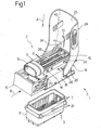
- number 1 indicates as a whole an electric connecting unit, in particular for connecting an electronic central control unit (not shown) to a vehicle electric system.
- Unit 1 substantially comprises a first plug connector 2 and a second socket connector 3 connectable to each other in a connection direction A.
- Connector 2 comprises an insulating casing 5 having a large number of cavities 6 extending parallel to direction A and for housing respective female electric terminals 4 (only one shown, withdrawn from the respective cavity, in Figure 1); and
- connector 3 comprises an insulating casing 6 conveniently formed in one piece with the outer casing (not shown) of the electronic central control unit, and a number of male electric terminals 7 extending parallel to direction A.
- Insulating casing 5 of connector 2 is substantially in the form of a hollow parallelepipedon, with a tubular lateral appendix 8 for guiding the cables 10 of respective electric terminals 4.
- unit 1 comprises a lever device 14 permitting guided mating of first connector 2 and second connector 3 with little manual effort.
- Device 14 substantially comprises a slide 15 (Figure 4) movable inside and with respect to casing 5 in a direction B perpendicular to direction A.
- Slide 15 is substantially C-shaped, and comprises two substantially flat lateral walls 16 spaced apart and parallel to directions A and B, and a transverse end wall 17. Lateral walls 16 of slide 15 slide inside respective lateral walls 18 of casing 5, and define a cavity 19 for receiving, in use, insulating casing 6 of connector 3.
- Each lateral wall 16 has a number of cam slots 20 which cooperate with respective pins 21 on the outside of casing 6 to produce an approach movement of connectors 2 and 3 in response to translation of slide 15 inwards of casing 5 in direction B.
- Each slot 20 comprises an input portion 20a parallel to direction A; an inclined intermediate portion 20b; and an end portion 20c parallel to direction B. More specifically ( Figure 4), the slots 20 close to the free ends of walls 16 have no input portions 20a, and the intermediate portions 20b terminate directly at said free ends.
- Device 14 also comprises a first-class lever 24 ( Figures 1 and 2) for activating slide 15, and which in turn comprises a substantially straight, elongated, C-section grip 25, and two lateral end arms 26.
- a first-class lever 24 ( Figures 1 and 2) for activating slide 15, and which in turn comprises a substantially straight, elongated, C-section grip 25, and two lateral end arms 26.
- Arms 26 comprise respective end pins 27 facing each other and defining an axis C of instantaneous rotation of lever 24 with respect to slide 15. Arms 26 extend on either side of casing 5, at respective openings 28 in the lateral walls 18 of casing 5, so that pins 27 engage in sliding manner respective slots 29 formed in respective end portions 30 of walls 16 of slide 15 and extending parallel to connection direction A.
- Lever 24 also comprises two appendixes 34, which extend from grip 25 (Figures 1 and 2) in a direction substantially parallel to and on the inside of arms 26.
- Appendixes 34 have respective slots 35 elongated substantially radially with respect to axis C, and are engaged in sliding manner by respective pins 36 carried laterally by casing 5 and defining an axis D permitting articulation of lever 24 with respect to casing 5.
- Arms 26 also comprise respective intermediate inner pins 37 of axis E parallel to and located in an intermediate position with respect to axes C and D.
- the top edges of lateral walls 16 of slide 15 have respective flanges 38 defining, with corresponding flanges 39 of casing 5, respective longitudinal guides 40 engaged in sliding manner by respective pins 37.
- Figure 5 shows lever 24 in the raised or open position, which corresponds to maximum projection of slide 15 from casing 5, and in which pins 36 engage the top ends of respective slots 35, lever 24 therefore has a maximum resisting arm, defined by the distance between axes C and D, and connector 2 may be mated with connector 3 so that pins 21 initially engage cam slots 20 of slide 15.
- lever 24 may be rotated downwards ( Figures 6 and 7) to translate slide 15 in direction B and so engage connectors 2, 3 and the respective electric terminals in direction A.
- Lever 24 and casing 5 have conventional click-on fastening means (43, 44) to lock lever 24 releasably in the closed position shown in Figure 7.
- lever 24 has a radial component of translation with respect to axis D, in the direction defined by slots 35 and substantially upwards with reference to the Figures, so that pins 36 slide along and towards the bottom ends of respective slots 35 towards pins 27, and the distance between axes D and C, which defines the resisting arm of lever 24, decreases gradually to the minimum value corresponding to the Figure 6 position.
- pins 21 interact with inclined intermediate portions 20a of cam slots 20, so that the intermediate stage in the rotation of lever 24 calls for overcoming the mating load of the connectors.
- lever 24 has a radial translation component in the opposite direction (i.e. towards axis C), and the resisting arm of lever 24 increases gradually until it is eventually restored to a relative maximum when pins 21 engage end portions 20c, parallel to direction B, of cam slots 20, which portions are reached when the connectors are fully mated.
- the value of the resisting arm of lever 24 is therefore greater and corresponds to smaller load amplification but greater displacement of slide 15 per unit rotation of lever 24; at the intermediate stage in the rotation of lever 24, in which the mating load is maximum, the value of the resisting arm of lever 24 is lower and corresponds to greater load amplification to mate the connectors with very little manual effort; and at the final stage in the travel of lever 24, in which the load to be overcome is again low, the value of the resisting arm of lever 24 is again high, and corresponds to smaller load amplification but greater displacement of slide 15 per unit of rotation of lever 24.
- the movable-axis articulation between lever 24 and casing 5 provides for varying the resisting arm of the lever during its travel, and so effectively reducing the manual activating load while at the same time favourable transmitting motion to slide 15 to reduce the dimensions and angular travel of the lever.
- lever 24 reduces friction, thus further reducing the activating load.
- lever device 14 may be carried by socket connector 3 as opposed to plug connector 2.
Landscapes
- Details Of Connecting Devices For Male And Female Coupling (AREA)
- Coupling Device And Connection With Printed Circuit (AREA)
- Connector Housings Or Holding Contact Members (AREA)
Claims (7)
- Elektrischer Steckverbinder (2) der Art mit einem Isoliergehäuse (5) mit einer Anzahl von Hohlräumen (10) für elektrische Anschlüsse (4), die sich in einer Verbindungsrichtung (A) des Steckverbinders (2) zu einem entgegengesetzten Steckverbinder (3) erstrecken; und einer Hebelvorrichtung (14) zum Reduzieren der zur Verbindung mit dem entgegengesetzten Steckverbinder (3) erforderlichen Kraft, wobei die Hebelvorrichtung (14) einen relativ zu dem Gehäuse (5) in einer Richtung (B) senkrecht zu der Verbindungsrichtung (A) gleitenden Schlitten (15) aufweist und eine mit dem entgegengesetzten Steckverbinder (3) wechselwirkende Nockeneinrichtung (20) besitzt, um als Reaktion auf eine Verschiebung des Schlittens (15) eine Kraft zum Ineinandergreifen der Steckverbinder (2, 3) zu erzeugen; und einem Aktivierungshebel (24) zum Aktivieren des Schlittens (15), der mit dem Schlitten (15) durch eine erste Gelenkverbindungseinrichtung (27, 29) und mit dem Gehäuse (5) durch eine zweite Gelenkverbindungseinrichtung (35, 36) verbunden ist,
dadurch gekennzeichnet, dass die erste und die zweite Gelenkverbindungseinrichtung ein Paar Drehgelenkelemente (27, 29; 35, 36) aufweisen, die miteinander in einer gleitenden Weise verbunden sind, um dem Aktivierungshebel (24) eine translatorische Bewegungskomponente zu erteilen; und
dass die Drehgelenkelemente (27, 29) der ersten Gelenkverbindungseinrichtung wenigstens einen ersten Stift (27) aufweisen, der eine erste Drehgelenkachse (C) definiert und in einer gleitenden Weise mit einem ersten Schlitz (29) in Eingriff steht, der in einer Richtung im Wesentlichen parallel zur Verbindungsrichtung (A) verlängert ist; die Drehgelenkelemente (35, 36) der zweiten Gelenkverbindungseinrichtung wenigstens einen zweiten Stift (36) aufweisen, der eine zweite Drehgelenkachse (D) definiert und in einer gleitenden Weise mit einem zweiten Schlitz (35) in Eingriff steht; der erste und der zweite Stift (27, 36) mit dem ersten bzw. dem zweiten Schlitz (29, 35) in einer gleitenden Weise in Eingriff stehen, um den Abstand zwischen der ersten und der zweiten Drehgelenkachse (C, D) entlang des Weges des Aktivierungshebels (24) zu verändern. - Steckverbinder nach Anspruch 1,
dadurch gekennzeichnet, dass der Aktivierungshebel (24) ein zweiarmiger Hebel ist;
dass die erste und die zweite Gelenkverbindungseinrichtung (27, 29; 35, 36) an einem Endabschnitt (26) bzw. einem Zwischenabschnitt (34) des Aktivierungshebels (24) angeordnet sind. - Steckverbinder nach Anspruch 1 oder 2,
dadurch gekennzeichnet, dass der zweite Schlitz (35) in einer im Wesentlichen radialen Richtung bezüglich der ersten Drehgelenkachse (C) verlängert ist. - Steckverbinder nach Anspruch 2 oder 3,
dadurch gekennzeichnet, dass der erste Stift (27) und der zweite Schlitz (35) durch den Aktivierungshebel (24) getragen sind;
dass der erste Schlitz (29) durch den Schlitten (15) getragen ist; und
dass der zweite Stift (36) durch das Gehäuse (5) getragen ist. - Steckverbinder nach einem der Ansprüche 3 bis 4,
dadurch gekennzeichnet, dass der Aktivierungshebel (24) wenigstens einen dritten Stift (37) aufweist, der an einer Zwischenposition zwischen der ersten und der zweiten Gelenkverbindungseinrichtung (27, 29; 35, 36) angeordnet ist und in einer gleitenden Weise mit einer durch wenigstens den Schlitten (15) des Gehäuses (5) definierten Führung (40) in Eingriff steht. - Steckverbinder nach Anspruch 5,
dadurch gekennzeichnet, dass die Führung (40) parallel zur Laufrichtung (B) des Schlittens (15) ist. - Steckverbinder nach Anspruch 5 oder 6,
dadurch gekennzeichnet, dass die Führung (40) durch jeweilige parallele Flansche (38, 39) des Gehäuses (5) und des Schlittens (15) definiert ist.
Applications Claiming Priority (2)
| Application Number | Priority Date | Filing Date | Title |
|---|---|---|---|
| IT1998TO001002A IT1303186B1 (it) | 1998-11-27 | 1998-11-27 | Connettore elettrico. |
| ITTO981002 | 1998-11-27 |
Publications (3)
| Publication Number | Publication Date |
|---|---|
| EP1005112A2 EP1005112A2 (de) | 2000-05-31 |
| EP1005112A3 EP1005112A3 (de) | 2000-11-08 |
| EP1005112B1 true EP1005112B1 (de) | 2005-08-17 |
Family
ID=11417212
Family Applications (1)
| Application Number | Title | Priority Date | Filing Date |
|---|---|---|---|
| EP99123511A Expired - Lifetime EP1005112B1 (de) | 1998-11-27 | 1999-11-25 | Elektrischer Verbinder |
Country Status (5)
| Country | Link |
|---|---|
| US (1) | US6345995B1 (de) |
| EP (1) | EP1005112B1 (de) |
| AT (1) | ATE302479T1 (de) |
| DE (1) | DE69926708T2 (de) |
| IT (1) | IT1303186B1 (de) |
Families Citing this family (46)
| Publication number | Priority date | Publication date | Assignee | Title |
|---|---|---|---|---|
| GB2334632B (en) * | 1998-02-23 | 2002-03-13 | Delphi Automotive Systems Gmbh | Two-part electrical connector |
| DE20013281U1 (de) * | 2000-08-02 | 2001-12-13 | Robert Bosch Gmbh, 70469 Stuttgart | Kabelbaumstecker mit einem Verriegelungsschieber und einer Vorverrastung |
| JP3492309B2 (ja) * | 2000-11-02 | 2004-02-03 | エフシーアイジャパン株式会社 | コネクタ |
| ITTO20010290A1 (it) * | 2001-03-27 | 2002-09-27 | Framatome Connectors Italia | Connetore elettrico. |
| DE20106746U1 (de) * | 2001-04-19 | 2002-08-29 | Robert Bosch Gmbh, 70469 Stuttgart | Kabelbaumstecker mit kompaktem Verriegelungselement in einer schüttelfesten und wasserdichten Ausführung |
| ES1049362Y (es) * | 2001-06-01 | 2002-04-16 | Lear Automotive Eeds Spain | Dispositivo perfeccionado de anclaje para caja de conectores en cajas de servicios. |
| ES1049360Y (es) * | 2001-06-01 | 2002-04-16 | Lear Automotive Eeds Spain | Dispositivo de conexion leva-guia |
| ES1050690Y (es) * | 2001-12-07 | 2002-08-16 | Lear Automotive Eeds Spain | Conector multifilar con dispositivo de enclavamiento. |
| ES1051490Y (es) * | 2001-12-21 | 2002-12-01 | Lear Automotive Eeds Spain | Conjunto modulo-conector estanco. |
| US20040253864A1 (en) * | 2001-12-21 | 2004-12-16 | Lear Corporation | Watertight connector-module assembly |
| DE10227591B3 (de) * | 2002-06-20 | 2004-02-05 | Fci | Verbinderanordnung |
| ITTO20020701A1 (it) * | 2002-08-06 | 2004-02-07 | Framatome Connectors Int | Connettore elettrico. |
| US6960090B2 (en) * | 2002-08-07 | 2005-11-01 | Tyco Electronics Amp Gmbh | Plug connector arrangement with latching actuation slide means |
| US6824406B1 (en) * | 2003-06-26 | 2004-11-30 | Delphi Technologies, Inc. | Electrical connector assembly |
| JP4001113B2 (ja) * | 2004-01-14 | 2007-10-31 | 住友電装株式会社 | レバー式コネクタ |
| KR100516513B1 (ko) * | 2004-02-19 | 2005-09-26 | 타이코에이엠피 주식회사 | 차량용 정션박스 및 그 조립방법 |
| US7070438B2 (en) * | 2004-03-31 | 2006-07-04 | Jst Corporation | Connector lever lock |
| US6971894B2 (en) * | 2004-03-31 | 2005-12-06 | Jst Corporation | Dual action mechanical assisted connector |
| US6899554B1 (en) * | 2004-04-19 | 2005-05-31 | Jst Corporation | Dual action mechanical assisted connector |
| ITTO20050089A1 (it) * | 2005-02-16 | 2006-08-17 | Fci Italia S P A | Connettore elettrico |
| KR100950350B1 (ko) * | 2005-04-08 | 2010-03-29 | 제이에스티 코포레이션 | 이중 작동 기계적 보조 커넥터 |
| JP4705675B2 (ja) * | 2005-04-08 | 2011-06-22 | ジェイエスティー コーポレーション | 二作動機械式支援コネクタ |
| US7361036B2 (en) * | 2005-10-06 | 2008-04-22 | Fci Americas Technology, Inc. | Electrical connector with lever and latch |
| JP4602218B2 (ja) * | 2005-10-18 | 2010-12-22 | 矢崎総業株式会社 | レバー式コネクタ |
| US7297031B2 (en) * | 2005-12-01 | 2007-11-20 | Advanced Testing Technologies, Inc. | Re-configurable electrical connectors |
| US7553198B1 (en) | 2005-12-01 | 2009-06-30 | Advanced Testing Technologies, Inc. | Re-configurable electrical connectors |
| US7416426B2 (en) * | 2006-01-31 | 2008-08-26 | Fci Americas Technology, Inc. | Push mate assisted electrical connector |
| DE102006058680A1 (de) * | 2006-12-13 | 2008-06-19 | Kostal Kontakt Systeme Gmbh | Elektrischer Steckverbinder |
| US20080242137A1 (en) * | 2007-03-30 | 2008-10-02 | General Electric Company | Single step operation connector assembly |
| JP4468465B2 (ja) * | 2008-03-28 | 2010-05-26 | タイコエレクトロニクスジャパン合同会社 | レバー式コネクタ |
| JP5135173B2 (ja) * | 2008-11-13 | 2013-01-30 | タイコエレクトロニクスジャパン合同会社 | 電気コネクタ組立体 |
| JP4523987B1 (ja) * | 2009-02-27 | 2010-08-11 | タイコエレクトロニクスジャパン合同会社 | スライドカム付きコネクタ |
| IT1398888B1 (it) * | 2010-03-04 | 2013-03-21 | Tyco Electronics Amp Italia Srl | Connettore elettrico |
| FR2971372B1 (fr) * | 2011-02-03 | 2013-11-29 | Tyco Electronics France Sas | Connecteur enfichable avec mecanisme de support de bonnette de protection arriere |
| US8469723B2 (en) | 2011-03-01 | 2013-06-25 | Advanced Testing Technologies, Inc. | Re-configurable electrical connectors |
| US9028163B2 (en) * | 2011-10-26 | 2015-05-12 | Alexander J. Advey | Lever-action connector assembly |
| JP5843167B2 (ja) * | 2012-11-15 | 2016-01-13 | 住友電装株式会社 | レバー式コネクタ |
| JP6339873B2 (ja) * | 2014-06-27 | 2018-06-06 | モレックス エルエルシー | コネクタ |
| US9379486B2 (en) * | 2014-11-20 | 2016-06-28 | Delphi Technologies, Inc. | Ratcheting lever actuated connector assembly |
| JP6607088B2 (ja) * | 2016-03-04 | 2019-11-20 | 住友電装株式会社 | コネクタ |
| US11171450B2 (en) | 2019-07-12 | 2021-11-09 | International Business Machines Corporation | Method and apparatus for the alignment and locking of removable elements with a connector |
| JP7249506B2 (ja) * | 2019-10-18 | 2023-03-31 | 株式会社オートネットワーク技術研究所 | レバー式コネクタ |
| US11233351B1 (en) * | 2020-09-29 | 2022-01-25 | Onanon, Inc. | Locking connector system |
| JP1706310S (ja) * | 2021-06-18 | 2022-01-31 | 電気コネクタ用ハウジング | |
| JP1706309S (ja) * | 2021-06-18 | 2022-01-31 | 電気コネクタ用ハウジング | |
| CN116073185B (zh) * | 2023-02-09 | 2025-11-21 | 昆山安费诺正日电子有限公司 | 电连接器及其电连接组件 |
Family Cites Families (9)
| Publication number | Priority date | Publication date | Assignee | Title |
|---|---|---|---|---|
| GB8823738D0 (en) | 1988-10-10 | 1988-11-16 | Amp Italia | Latching mechanism for plug & socket type electrical connector |
| DE3930772A1 (de) * | 1989-09-14 | 1991-03-28 | Elco Elektronik Gmbh | Elektrische kontaktsteckvorrichtung |
| US5876226A (en) * | 1994-10-14 | 1999-03-02 | The Whitaker Corporation | Connector with cam member |
| JP3050275B2 (ja) * | 1994-11-29 | 2000-06-12 | 矢崎総業株式会社 | レバー嵌合式コネクタ |
| DE4443349C2 (de) * | 1994-12-06 | 1996-09-26 | Delphi Automotive Systems Gmbh | Elektrische Steckverbindung |
| EP0722203B1 (de) * | 1995-01-16 | 2003-04-16 | Molex Incorporated | Elektrischer Steckverbinder mit verbessertem Nockensystem |
| FR2730587B3 (fr) * | 1995-02-09 | 1997-04-30 | Amp France | Connecteur electrique a mecanismes de verrouillage secondaire et d'accouplement |
| DE19651436A1 (de) * | 1996-12-11 | 1998-06-18 | Bosch Gmbh Robert | Vorrichtung zum Verbinden von elektrischen Kontakten |
| JP3345566B2 (ja) * | 1997-07-01 | 2002-11-18 | 矢崎総業株式会社 | レバー嵌合式コネクタ |
-
1998
- 1998-11-27 IT IT1998TO001002A patent/IT1303186B1/it active IP Right Grant
-
1999
- 1999-11-23 US US09/448,006 patent/US6345995B1/en not_active Expired - Lifetime
- 1999-11-25 AT AT99123511T patent/ATE302479T1/de not_active IP Right Cessation
- 1999-11-25 EP EP99123511A patent/EP1005112B1/de not_active Expired - Lifetime
- 1999-11-25 DE DE69926708T patent/DE69926708T2/de not_active Expired - Lifetime
Also Published As
| Publication number | Publication date |
|---|---|
| ITTO981002A1 (it) | 2000-05-27 |
| ITTO981002A0 (it) | 1998-11-27 |
| DE69926708D1 (de) | 2005-09-22 |
| ATE302479T1 (de) | 2005-09-15 |
| DE69926708T2 (de) | 2006-06-22 |
| US6345995B1 (en) | 2002-02-12 |
| EP1005112A3 (de) | 2000-11-08 |
| EP1005112A2 (de) | 2000-05-31 |
| IT1303186B1 (it) | 2000-10-30 |
Similar Documents
| Publication | Publication Date | Title |
|---|---|---|
| US6345995B1 (en) | Electric connector | |
| US5681175A (en) | Electrical connector assembly with improved camming system | |
| EP0991145B1 (de) | Zweiteiliger Steckverbinder | |
| EP0938162B1 (de) | Zweiteiliger elektrischer Steckverbinder | |
| US4778403A (en) | Zero insertion force connector | |
| US5474461A (en) | Lever-operated connector | |
| EP1396052B1 (de) | Elektrischer steckverbinder | |
| US7347710B2 (en) | Electric wire connector having a lock securing mechanism | |
| EP0582866B1 (de) | Elektrischer Verbinder mit sekundärem Sperrmechanismus | |
| US6709165B2 (en) | Plug portion for an optical plug connection | |
| US6325680B1 (en) | Female contact for an electrical connector | |
| EP0790676A2 (de) | Hebelverbinder | |
| EP0933836A2 (de) | Verbinder mit Kupplungshilfsmechanismus | |
| US6464532B1 (en) | Connector for a flat foil conductor | |
| GB2377325A (en) | Lever type connector | |
| EP0667654B1 (de) | Elektrischer Stecker mit verbesserter Vorrichtung zum Verriegeln und Entriegeln | |
| US5785540A (en) | Electrical connector with an actuating slide | |
| EP0630075B1 (de) | Steckverbinder mit Betätigungshebel und Verfahren für die Zusammensetzung und Verbindung | |
| EP1905134B1 (de) | Elektrischer verbinder | |
| KR19980063818A (ko) | 전기 접점 연결 장치 | |
| EP2180558A1 (de) | Verbinder mit Selbsthaltefeststellvorrichtung | |
| GB2305786A (en) | Electrical connector with guiding structure | |
| EP1024560B1 (de) | Zweiteiliger elektrischer Verbinder | |
| EP0731535A2 (de) | Elektrischer Verbinder versehen mit einem Nockenmechanismus | |
| US5876254A (en) | Apparatus for securing contacts in a contact housing |
Legal Events
| Date | Code | Title | Description |
|---|---|---|---|
| PUAI | Public reference made under article 153(3) epc to a published international application that has entered the european phase |
Free format text: ORIGINAL CODE: 0009012 |
|
| AK | Designated contracting states |
Kind code of ref document: A2 Designated state(s): AT BE CH CY DE DK ES FI FR GB GR IE IT LI LU MC NL PT SE |
|
| AX | Request for extension of the european patent |
Free format text: AL;LT;LV;MK;RO;SI |
|
| PUAL | Search report despatched |
Free format text: ORIGINAL CODE: 0009013 |
|
| AK | Designated contracting states |
Kind code of ref document: A3 Designated state(s): AT BE CH CY DE DK ES FI FR GB GR IE IT LI LU MC NL PT SE |
|
| AX | Request for extension of the european patent |
Free format text: AL;LT;LV;MK;RO;SI |
|
| 17P | Request for examination filed |
Effective date: 20010226 |
|
| AKX | Designation fees paid |
Free format text: AT BE CH CY DE DK ES FI FR GB GR IE IT LI LU MC NL PT SE |
|
| RAP1 | Party data changed (applicant data changed or rights of an application transferred) |
Owner name: FCI |
|
| GRAP | Despatch of communication of intention to grant a patent |
Free format text: ORIGINAL CODE: EPIDOSNIGR1 |
|
| GRAS | Grant fee paid |
Free format text: ORIGINAL CODE: EPIDOSNIGR3 |
|
| GRAA | (expected) grant |
Free format text: ORIGINAL CODE: 0009210 |
|
| RAP1 | Party data changed (applicant data changed or rights of an application transferred) |
Owner name: FCI |
|
| AK | Designated contracting states |
Kind code of ref document: B1 Designated state(s): AT BE CH CY DE DK ES FI FR GB GR IE IT LI LU MC NL PT SE |
|
| PG25 | Lapsed in a contracting state [announced via postgrant information from national office to epo] |
Ref country code: NL Free format text: LAPSE BECAUSE OF FAILURE TO SUBMIT A TRANSLATION OF THE DESCRIPTION OR TO PAY THE FEE WITHIN THE PRESCRIBED TIME-LIMIT Effective date: 20050817 Ref country code: LI Free format text: LAPSE BECAUSE OF FAILURE TO SUBMIT A TRANSLATION OF THE DESCRIPTION OR TO PAY THE FEE WITHIN THE PRESCRIBED TIME-LIMIT Effective date: 20050817 Ref country code: IT Free format text: LAPSE BECAUSE OF FAILURE TO SUBMIT A TRANSLATION OF THE DESCRIPTION OR TO PAY THE FEE WITHIN THE PRESCRIBED TIME-LIMIT;WARNING: LAPSES OF ITALIAN PATENTS WITH EFFECTIVE DATE BEFORE 2007 MAY HAVE OCCURRED AT ANY TIME BEFORE 2007. THE CORRECT EFFECTIVE DATE MAY BE DIFFERENT FROM THE ONE RECORDED. Effective date: 20050817 Ref country code: FI Free format text: LAPSE BECAUSE OF FAILURE TO SUBMIT A TRANSLATION OF THE DESCRIPTION OR TO PAY THE FEE WITHIN THE PRESCRIBED TIME-LIMIT Effective date: 20050817 Ref country code: CH Free format text: LAPSE BECAUSE OF FAILURE TO SUBMIT A TRANSLATION OF THE DESCRIPTION OR TO PAY THE FEE WITHIN THE PRESCRIBED TIME-LIMIT Effective date: 20050817 Ref country code: BE Free format text: LAPSE BECAUSE OF FAILURE TO SUBMIT A TRANSLATION OF THE DESCRIPTION OR TO PAY THE FEE WITHIN THE PRESCRIBED TIME-LIMIT Effective date: 20050817 Ref country code: AT Free format text: LAPSE BECAUSE OF FAILURE TO SUBMIT A TRANSLATION OF THE DESCRIPTION OR TO PAY THE FEE WITHIN THE PRESCRIBED TIME-LIMIT Effective date: 20050817 |
|
| REG | Reference to a national code |
Ref country code: GB Ref legal event code: FG4D |
|
| REG | Reference to a national code |
Ref country code: CH Ref legal event code: EP |
|
| REG | Reference to a national code |
Ref country code: IE Ref legal event code: FG4D |
|
| REF | Corresponds to: |
Ref document number: 69926708 Country of ref document: DE Date of ref document: 20050922 Kind code of ref document: P |
|
| PG25 | Lapsed in a contracting state [announced via postgrant information from national office to epo] |
Ref country code: SE Free format text: LAPSE BECAUSE OF FAILURE TO SUBMIT A TRANSLATION OF THE DESCRIPTION OR TO PAY THE FEE WITHIN THE PRESCRIBED TIME-LIMIT Effective date: 20051117 Ref country code: GR Free format text: LAPSE BECAUSE OF FAILURE TO SUBMIT A TRANSLATION OF THE DESCRIPTION OR TO PAY THE FEE WITHIN THE PRESCRIBED TIME-LIMIT Effective date: 20051117 Ref country code: DK Free format text: LAPSE BECAUSE OF FAILURE TO SUBMIT A TRANSLATION OF THE DESCRIPTION OR TO PAY THE FEE WITHIN THE PRESCRIBED TIME-LIMIT Effective date: 20051117 |
|
| PG25 | Lapsed in a contracting state [announced via postgrant information from national office to epo] |
Ref country code: IE Free format text: LAPSE BECAUSE OF NON-PAYMENT OF DUE FEES Effective date: 20051125 Ref country code: GB Free format text: LAPSE BECAUSE OF NON-PAYMENT OF DUE FEES Effective date: 20051125 Ref country code: CY Free format text: LAPSE BECAUSE OF FAILURE TO SUBMIT A TRANSLATION OF THE DESCRIPTION OR TO PAY THE FEE WITHIN THE PRESCRIBED TIME-LIMIT Effective date: 20051125 |
|
| PG25 | Lapsed in a contracting state [announced via postgrant information from national office to epo] |
Ref country code: ES Free format text: LAPSE BECAUSE OF FAILURE TO SUBMIT A TRANSLATION OF THE DESCRIPTION OR TO PAY THE FEE WITHIN THE PRESCRIBED TIME-LIMIT Effective date: 20051128 |
|
| PG25 | Lapsed in a contracting state [announced via postgrant information from national office to epo] |
Ref country code: MC Free format text: LAPSE BECAUSE OF NON-PAYMENT OF DUE FEES Effective date: 20051130 Ref country code: LU Free format text: LAPSE BECAUSE OF NON-PAYMENT OF DUE FEES Effective date: 20051130 |
|
| PG25 | Lapsed in a contracting state [announced via postgrant information from national office to epo] |
Ref country code: PT Free format text: LAPSE BECAUSE OF FAILURE TO SUBMIT A TRANSLATION OF THE DESCRIPTION OR TO PAY THE FEE WITHIN THE PRESCRIBED TIME-LIMIT Effective date: 20060117 |
|
| NLV1 | Nl: lapsed or annulled due to failure to fulfill the requirements of art. 29p and 29m of the patents act | ||
| REG | Reference to a national code |
Ref country code: CH Ref legal event code: PL |
|
| ET | Fr: translation filed | ||
| PLBE | No opposition filed within time limit |
Free format text: ORIGINAL CODE: 0009261 |
|
| STAA | Information on the status of an ep patent application or granted ep patent |
Free format text: STATUS: NO OPPOSITION FILED WITHIN TIME LIMIT |
|
| 26N | No opposition filed |
Effective date: 20060518 |
|
| GBPC | Gb: european patent ceased through non-payment of renewal fee |
Effective date: 20051125 |
|
| REG | Reference to a national code |
Ref country code: IE Ref legal event code: MM4A |
|
| REG | Reference to a national code |
Ref country code: FR Ref legal event code: CA |
|
| REG | Reference to a national code |
Ref country code: FR Ref legal event code: TP |
|
| REG | Reference to a national code |
Ref country code: FR Ref legal event code: GC |
|
| REG | Reference to a national code |
Ref country code: DE Ref legal event code: R082 Ref document number: 69926708 Country of ref document: DE Representative=s name: MITSCHERLICH, PATENT- UND RECHTSANWAELTE PARTM, DE Effective date: 20120419 Ref country code: DE Ref legal event code: R082 Ref document number: 69926708 Country of ref document: DE Representative=s name: MITSCHERLICH, PATENT- UND RECHTSANWAELTE, PART, DE Effective date: 20120419 Ref country code: DE Ref legal event code: R081 Ref document number: 69926708 Country of ref document: DE Owner name: DELPHI INTERNATIONAL OPERATIONS LUXEMBOURG S.A, LU Free format text: FORMER OWNER: FCI, VERSAILLES, FR Effective date: 20120419 |
|
| REG | Reference to a national code |
Ref country code: DE Ref legal event code: R082 Ref document number: 69926708 Country of ref document: DE Representative=s name: MITSCHERLICH, PATENT- UND RECHTSANWAELTE PARTM, DE Effective date: 20120628 Ref country code: DE Ref legal event code: R082 Ref document number: 69926708 Country of ref document: DE Representative=s name: MITSCHERLICH, PATENT- UND RECHTSANWAELTE, PART, DE Effective date: 20120628 Ref country code: DE Ref legal event code: R081 Ref document number: 69926708 Country of ref document: DE Owner name: DELPHI INTERNATIONAL OPERATIONS LUXEMBOURG S.A, LU Free format text: FORMER OWNER: FCI, GUYANCOURT, FR Effective date: 20120628 |
|
| REG | Reference to a national code |
Ref country code: FR Ref legal event code: TP Owner name: DELPHI INTERNATIONAL OPERATIONS LUXEMBOURG S.A, LU Effective date: 20140715 |
|
| REG | Reference to a national code |
Ref country code: DE Ref legal event code: R082 Ref document number: 69926708 Country of ref document: DE Representative=s name: MITSCHERLICH, PATENT- UND RECHTSANWAELTE, PART, DE |
|
| REG | Reference to a national code |
Ref country code: DE Ref legal event code: R082 Ref document number: 69926708 Country of ref document: DE Representative=s name: MITSCHERLICH, PATENT- UND RECHTSANWAELTE PARTM, DE Effective date: 20141106 Ref country code: DE Ref legal event code: R082 Ref document number: 69926708 Country of ref document: DE Representative=s name: MITSCHERLICH, PATENT- UND RECHTSANWAELTE, PART, DE Effective date: 20141106 Ref country code: DE Ref legal event code: R081 Ref document number: 69926708 Country of ref document: DE Owner name: DELPHI INTERNATIONAL OPERATIONS LUXEMBOURG S.A, LU Free format text: FORMER OWNER: FCI AUTOMOTIVE HOLDING, GUYANCOURT, FR Effective date: 20141106 |
|
| REG | Reference to a national code |
Ref country code: FR Ref legal event code: PLFP Year of fee payment: 17 |
|
| REG | Reference to a national code |
Ref country code: FR Ref legal event code: PLFP Year of fee payment: 18 |
|
| REG | Reference to a national code |
Ref country code: FR Ref legal event code: PLFP Year of fee payment: 19 |
|
| REG | Reference to a national code |
Ref country code: DE Ref legal event code: R082 Ref document number: 69926708 Country of ref document: DE Ref country code: DE Ref legal event code: R081 Ref document number: 69926708 Country of ref document: DE Owner name: APTIV TECHNOLOGIES LIMITED, BB Free format text: FORMER OWNER: DELPHI INTERNATIONAL OPERATIONS LUXEMBOURG S.A R.L., BASCHARAGE, LU |
|
| PGFP | Annual fee paid to national office [announced via postgrant information from national office to epo] |
Ref country code: DE Payment date: 20181128 Year of fee payment: 20 |
|
| PGFP | Annual fee paid to national office [announced via postgrant information from national office to epo] |
Ref country code: FR Payment date: 20181127 Year of fee payment: 20 |
|
| REG | Reference to a national code |
Ref country code: DE Ref legal event code: R071 Ref document number: 69926708 Country of ref document: DE |