EP1005175A2 - Verfahren zur Antennen-Ausrichtung zur Datenübertragung zwischen sich bewegenden Fahrzeugen und Vorrichtung zur Durchführung des Verfahrens - Google Patents
Verfahren zur Antennen-Ausrichtung zur Datenübertragung zwischen sich bewegenden Fahrzeugen und Vorrichtung zur Durchführung des Verfahrens Download PDFInfo
- Publication number
- EP1005175A2 EP1005175A2 EP99122887A EP99122887A EP1005175A2 EP 1005175 A2 EP1005175 A2 EP 1005175A2 EP 99122887 A EP99122887 A EP 99122887A EP 99122887 A EP99122887 A EP 99122887A EP 1005175 A2 EP1005175 A2 EP 1005175A2
- Authority
- EP
- European Patent Office
- Prior art keywords
- partial
- antenna
- antennas
- transmission
- arrangement
- Prior art date
- Legal status (The legal status is an assumption and is not a legal conclusion. Google has not performed a legal analysis and makes no representation as to the accuracy of the status listed.)
- Granted
Links
Images


Classifications
-
- H—ELECTRICITY
- H04—ELECTRIC COMMUNICATION TECHNIQUE
- H04B—TRANSMISSION
- H04B7/00—Radio transmission systems, i.e. using radiation field
- H04B7/14—Relay systems
- H04B7/15—Active relay systems
- H04B7/185—Space-based or airborne stations; Stations for satellite systems
- H04B7/18502—Airborne stations
- H04B7/18506—Communications with or from aircraft, i.e. aeronautical mobile service
-
- H—ELECTRICITY
- H01—ELECTRIC ELEMENTS
- H01Q—ANTENNAS, i.e. RADIO AERIALS
- H01Q1/00—Details of, or arrangements associated with, antennas
- H01Q1/27—Adaptation for use in or on movable bodies
- H01Q1/28—Adaptation for use in or on aircraft, missiles, satellites, or balloons
-
- H—ELECTRICITY
- H01—ELECTRIC ELEMENTS
- H01Q—ANTENNAS, i.e. RADIO AERIALS
- H01Q19/00—Combinations of primary active antenna elements and units with secondary devices, e.g. with quasi-optical devices, for giving the antenna a desired directional characteristic
- H01Q19/10—Combinations of primary active antenna elements and units with secondary devices, e.g. with quasi-optical devices, for giving the antenna a desired directional characteristic using reflecting surfaces
- H01Q19/12—Combinations of primary active antenna elements and units with secondary devices, e.g. with quasi-optical devices, for giving the antenna a desired directional characteristic using reflecting surfaces wherein the surfaces are concave
- H01Q19/17—Combinations of primary active antenna elements and units with secondary devices, e.g. with quasi-optical devices, for giving the antenna a desired directional characteristic using reflecting surfaces wherein the surfaces are concave the primary radiating source comprising two or more radiating elements
-
- H—ELECTRICITY
- H01—ELECTRIC ELEMENTS
- H01Q—ANTENNAS, i.e. RADIO AERIALS
- H01Q3/00—Arrangements for changing or varying the orientation or the shape of the directional pattern of the waves radiated from an antenna or antenna system
- H01Q3/24—Arrangements for changing or varying the orientation or the shape of the directional pattern of the waves radiated from an antenna or antenna system varying the orientation by switching energy from one active radiating element to another, e.g. for beam switching
Definitions
- the invention relates to a method for automatic antenna alignment of antennas on moving vehicles and especially aircraft arbitrary locations in such a way that a data transmission between these vehicles or devices can take place.
- the invention relates also an apparatus for performing this method.
- a control signal is generated from the levels of the level derived from the received signal that the antennas continuously on the Track maximum of the antenna lobe.
- the object of the invention is therefore to provide a method and an apparatus for automatic antenna alignment and switching for To create data transmission between moving vehicles who have no information regarding the position and direction of the directional antennas assigned in the transmission is required.
- Another object of the invention is the use of antenna switching to select a specific remote site with which the Communication should be carried out.
- the selection of the remote site should according to an identifier of the respective remote site.
- An advantage of the invention is that without using antennas Shot peening characteristic of the entire area around the respective vehicle around is covered with the antenna arrangement according to the invention.
- Each antenna of an antenna arrangement becomes a proportionate one inexpensive receiver assigned to the corresponding for the transmission Identification and control signals only have to be relatively narrowband. For the actual data transmission is just a broadband receiver for that entire antenna arrangement of one vehicle required. Thereby the entire antenna arrangement becomes relatively inexpensive.
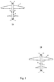
- FIG. 1 shows a first antenna arrangement 11 with the antennas, hereinafter called partial antennas or partial exciters 12, 13, 14, 15, 16 17, the embodiment described in Figure 1 over the peripheral surface an aircraft fuselage 18 of a first vehicle or aircraft 20 are attached, in Figure 1 is also a second antenna arrangement 21 shown with the partial antennas or partial exciters 22, 23, 24, 25, 26, 27, those on the fuselage 19 of a second vehicle or aircraft 28 are attached.
- first antenna arrangement 11 with the antennas, hereinafter called partial antennas or partial exciters 12, 13, 14, 15, 16 17, the embodiment described in Figure 1 over the peripheral surface an aircraft fuselage 18 of a first vehicle or aircraft 20 are attached
- Figure 1 is also a second antenna arrangement 21 shown with the partial antennas or partial exciters 22, 23, 24, 25, 26, 27, those on the fuselage 19 of a second vehicle or aircraft 28 are attached.
- each or some of these sub-antennas 12, 13, 14, 15, 16 or 22, 23, 24, 25, 26, 27 of the first 20 or second 28 aircraft by one in FIGS 4 antenna arrangements 31 and 41 shown are replaced.
- a first antenna arrangement 31 with the Partial antennas or pathogens 32, 33, 34, 35, 36 and 37, and a second Antenna arrangement 41 with the partial antennas or partial exciters 42, 43, 44, 45, 46 and 47 are shown.
- 5 shows the antenna diagrams shown, which in an arrangement with parabolic antennas e.g. according to the Figure 3 or 4 arise, the parabolic antennas also after the Cassegrain principle can be carried out.
- FIG. 6 is a block diagram of the antenna alignment system according to the invention 51 shown in the exchange Vehicles, both in the sending vehicle and in each receiving vehicle is present.
- the antenna alignment system comprises several functional groups or end devices 52, 53, 54, 55, 56, wherein each function group is integrated in the partial antenna.
- Each functional group e.g. B. the function group 52, comprises a transmission branch 61 and one Receive branch 62.
- the respective end of the transmission branch 61 or the beginning of the receiving branch 62 is to that partial antenna or to that Partial exciter connected, the or the respective function group 52 assigned.
- the partial antenna assigned to the function group 52 is in the representation of Figure 6 by means of two symbols shown, namely a transmitting antenna 63 and a receiving antenna 64, the transmitting antenna 63 and the receiving antenna 64 in terms of technology preferably from a partial antenna, e.g. B. the partial antenna 15 of FIG. 1 or e.g. of the partial antenna 32 of FIGS. 3 or 4.
- a partial antenna e.g. B. the partial antenna 15 of FIG. 1 or e.g. of the partial antenna 32 of FIGS. 3 or 4.
- Right away on the transmitting antenna 63 and on the receiving antenna 64 is one Amplifier 65 and 66 arranged.
- transmission branch 61 is from Transmitting antenna 63 seen from the amplifier 65, a switch 67 provided from where the line of the transmission branch 61 to a modulator 69 arrives.
- switch 67 is a Understand device that connects the selected transmit antenna.
- the switching function of the switch 67 can also be switched on and off Switching off the supply voltage of the amplifier 65 can be realized.
- the modulator 69 is fed by a high-frequency generator 69a.
- the Useful data to be sent via the transmission branch 61 are sent to the modulator 69 fed from a corresponding user data source 69b.
- in the Receive branch 62 branches the signal from the receive antenna 64 seen behind the amplifier 66 on a rectifier 72, a filter and in particular a low-pass filter 73 and a low-frequency amplifier 74. This signal forms what is required for antenna switching Control signal 64a, which opens into a control unit 77, which in turn itself has a line 78 to the modulator 69 and the lines for switching the switches 67 and 71 are assigned.
- the functional groups 52, 53, 54, 55, 56 preferably each have the same structure and the same components with the same functions on. Accordingly, components are in the different Function groups of Figure 6, which have the same function with shown the same reference number. Corresponding connections between a function group 52, 53, 54, 55, 56 and the control unit 77 are provided (not shown in Figure 6).
- the control unit 77 is connected to each of the corresponding lines 79 Switches 67 of the transmission branch 61 of each function group 52, 53, 54, 55, 56 in connection.
- the control unit 77 is capable of at least one Transmitting branch 61 or at least one partial antenna 63 one To activate antenna arrangement 11, 21, 31, 41.
- Each switch 71 one Function group 52, 53, 54, 55, 56 is in each case via a line 81a, 81b, 81c, 81d, 81e connected to a summation circuit 82, which in turn with communicates with a receiver 83.
- the receiver 83 is preferably a broadband receiver and has preferably an amplifier 83a, a filter device 83b and one Demodulator 83c.
- a line 84 runs from demodulator 83c to one User data sink or a consumer 85.
- the function groups 52, 53, 54, 55, 56 of the antenna units are each integrated on or in a partial antenna 12, the Attenuation of cables or networks connected to the end amplifiers 65 or the preamplifiers 66 are connected to be eliminated. Thereby can significantly improve system sensitivity and Reduction of electricity consumption compared to the prior art can be achieved.
- the function groups 52, 53, 54, 55, 56 are expediently manufactured in inexpensive chip or SMD technology and integrated or embedded in the antenna circuit boards (not shown).
- Each sub-antenna 64 can be assigned by means of the respectively assigned function groups 52, 53, 54, 55 and 56 of the receiving branch 62 and the control unit 77 a narrowband control mode or a broadband Data transmission mode can be switched.
- Each functional group is 52, 53, 54, 55, 56 parallel, d. H. at the same time on the more narrow-band and more sensitive Control mode switched.
- the tax data flows from the Receive antennas 64 from the receive branches 62 into the lines 64a, 64b, 64c, 64d, 64e, via which the control signals into the control unit 67 reach.
- Those for this narrow band and therefore sensitive Control channel provided elements such as amplifier 66, filter 72 and the NF amplifier 74 requires little power.
- the signals in this circuit are simple to keep narrowband control mode only amplitude or pulse modulated.
- the narrow band control mode is used to determine whether from others Vehicles, d. H. from whose transmitters data is sent and especially from which direction the data is sent.
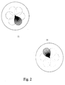
- the Partial antennas 12, 13, 14, 15, 16, 17; 22, 23, 24, 25, 26, 27 of the respective Antenna arrangement 11, 21, 31 or 41 or the partial exciters 32, 33, 34, 35, 36, 37; 42, 43, 44, 45, 46, 47 of the respective antenna arrangement are such arranged that the antenna diagrams of the respective antenna arrangement 11, 21, 31, 41, which are aligned over a large angular range are also overlapping each other in a predetermined manner. Thereby it is ensured that each antenna arrangement 11, 21, 31, 41 a wide Area or at least one area that covers that for the useful data transmission considered angular range includes (Figure 2).
- the antenna alignment system 51 uses the narrowband Control mode determines that and from which direction data is sent should. For tax and direction determination is preferably from a corresponding call sign of the receiving station in each case Station as well as a call sign of the own sending station. This call is preferably made one after the other, i.e. the switchover takes place after each control word or by quickly switching within a bit over each of the different sub-antennas of the transmitting station or the transmitting antenna alignment system 51.
- All receiving partial antennas or in relation to the transmitting station existing remote sites of the receiving vehicle receive the Signals from the sending station or the sending station Antenna arrangement, the respective remote station being addressed on the basis of of the received call signals notices when it has been addressed. Thereupon only the addressed partner answers, with the partial antenna with which the call signal was received. So it will answered only in the direction from which the call signal was received.
- Receive several sub-antennas of one antenna arrangement each at the same time call signals the partial antenna is selected that the received the largest or strongest signal. Alternatively, you can several sub-antennas are selected, with a given one Minimum level of the received signal has been reached. Should this Minimum level for several, e.g.
- the neighboring sub-antennas reached can also be used in the broadband channel for the transmission of user data to the sum amplifier via switch 71 be switched through. However, it must be in phase between the sub-antennas and the sum amplifier prevail.
- the response signal contains both the identifier of the previously transmitting station and the Identifier of the responding station.
- the one receiving the response signal and sending it originally or previously The station again determines the direction from which the Signal was received, d. H. it determines the partial antenna of the respective one Antenna arrangement with the strongest signal.
- the narrow-band control mode therefore only serves that sub-antenna to select an antenna arrangement whose antenna diagram on most likely points in the direction from which a call signal was received. Through the additionally communicated identification of the respective stations only selected the stations required for the data connection.
- the receiving antenna alignment system 51 switches 51 from control mode or control mode to Data transmission operation around.
- the fact that antennas directed to the actual data transmission higher transmission bandwidth are used Data transmission larger ranges with a relatively small Transmission power achieved.
- different data links can also be used by more than one receiver 83 can be used within an antenna alignment system 51.
- the number of receivers 83 is within an antenna pointing system 51 in relation to the function groups 52, 53, 54, 55, 56 significantly lower.
- To increase data security more complex types of modulation than used in control mode, e.g. 8. Frequency, phase, spread spectrum or similar modulations used.
- the transmitted data can for security reasons additionally encrypted.
- the data transmission is preferably carried out in the following way:
- the respective transmitting station or the respective transmitting antenna alignment system 51 transmits a block of data to the receiving antenna alignment system 51.
- This is the direction of transmission in control mode from the sending station sent callsign repeated so that the correct direction of transmission confirmed or corrected as described above.
- An additional The symbol confirms the correct transmission of the data block by the Check format syntax, parity etc. or request repetition of the data block just sent. Then there will be a transfer or answer in the opposite direction, i.e. from the previously receiving to the previously transmitting antenna alignment system 51, this becomes necessary announced by an appropriate sign.
- this call sign or this announcement is sent by the transmitting antenna pointing system 51 another block of data.
Landscapes
- Engineering & Computer Science (AREA)
- Physics & Mathematics (AREA)
- Astronomy & Astrophysics (AREA)
- Aviation & Aerospace Engineering (AREA)
- General Physics & Mathematics (AREA)
- Signal Processing (AREA)
- Computer Networks & Wireless Communication (AREA)
- Remote Sensing (AREA)
- Mobile Radio Communication Systems (AREA)
- Traffic Control Systems (AREA)
- Near-Field Transmission Systems (AREA)
- Radio Relay Systems (AREA)
- Variable-Direction Aerials And Aerial Arrays (AREA)
Abstract
Description
Claims (3)
- Verfahren zum Aufbau und zur Durchführung einer Nutzdaten-Übertragung zwischen sich relativ zueinander bewegenden Fahrzeugen oder Flugzeugen (1) mittels einer Anordnung (11, 21, 31, 41) von Teil-Antennen (12, 13, 14, 15, 16, 17; 22, 23, 24, 25, 26, 27; 32, 33, 34, 35, 36, 37; 42, 43, 44, 45, 46, 47; 63, 63) mit den Schritten:Durchführung des Steuer-Modus mit der Aktivierung einer Mehrzahl der (Teil-)Antennen einer Antennen-Anordnung (11, 21, 31, 41), wobei die Teil-Antennen in vorbestimmter Weise an jedem für die Nutzdaten-Übertragung beteiligten Fahrzeug (1) derart angeordnet sind, daß der für die Nutzdaten-Übertragung in Betracht kommende Winkelbereich durch die von der Anordnung von Teil-Antennen erzeugten Antennen-Diagramme (11, 21) abgedeckt ist,Übertragung eines Such-Signals über eine Mehrzahl der Teil-Antennen jeder Anordnung (11, 21, 31, 41) von Teil-Antennen zur Ermittlung der Richtung zum jeweiligen Sender bzw. Empfänger,zur Nutzdaten-Übertragung bei jedem an der Kommunikation beteiligten Fahrzeug (1) Auswahl und Zuschaltung derjenigen Teil-Antenne der jeweils am Fahrzeug (1) angeordneten Antennen-Anordnung (11, 21, 31, 41), bei der die Daten zur Identifikation mit einem Mindest-Pegel empfangen worden sind,Nutzdaten-Übertragung über die im Steuer-Modus ausgewählte Teil-Antenne.
- Vorrichtung zur Durchführung des Verfahrens nach dem Anspruch 1 mit einer Anzahl von Teil-Antennen, die in vorbestimmter Weise an jedem für die Nutzdaten-Übertragung beteiligten Fahrzeug (1) derart angeordnet sind, daß der für die Nutzdaten-Übertragung in Betracht kommende Winkelbereich durch die von der Anordnung von Teil-Antennen erzeugten Antennen-Diagramme abgedeckt ist,mit einem jeder Teil-Antenne (12, 13, 14, 15, 16, 17; 22, 23, 24, 25, 26, 27; 32, 33, 34, 35, 36, 37; 42, 43, 44, 45, 46, 47; 63, 63) zugeordneten Sendezweig (61), der zum Sender durchgeschaltet werden kannmit einem Empfangszweig (62) mit einem Empfänger (83), der mit einer Mehrzahl der Teil-Antennen über jeweils einen Schalter (71) in Verbindung steht und mit dem in einem Steuer-Modus gleichzeitig Rufsignale von einer Mehrzahl der Teil-Antennen empfangen werden können,mit einer Steuer-Einheit (77), die mit einer Mehrzahl der Teil-Antennen über jeweils einen Schalter (67) in Verbindung steht, über den die Steuer-Einheit (77) den Sendezweig (61) einer Teil-Antenne aktiviert, sobald der Empfänger (83) ein Rufsignal von einer Gegenstelle empfangen hat,
wobei die Auswahl der Teil-Antenne aufgrund der Stärke des von dieser Teil-Antenne empfangenen Ruf-Signals erfolgt. - Vorrichtung mit einer Anzahl von Teil-Antennen nach dem Anspruch 2, dadurch gekennzeichnet, daß die Teil-Antennen (12, 13, 14, 15, 16, 17; 22, 23, 24, 25, 26, 27; 32, 33, 34, 35, 36, 37; 42, 43, 44, 45, 46, 47; 63, 63) Teil-Erreger einer Antennen-Anordnung (31, 41) eines Parabolspiegels darstellen.
Applications Claiming Priority (2)
| Application Number | Priority Date | Filing Date | Title |
|---|---|---|---|
| DE19853905 | 1998-11-23 | ||
| DE19853905A DE19853905C2 (de) | 1998-11-23 | 1998-11-23 | Verfahren zur Antennen-Ausrichtung zur Datenübertragung zwischen sich bewegenden Fahrzeugen und Vorrichtung zur Durchführung des Verfahrens |
Publications (3)
| Publication Number | Publication Date |
|---|---|
| EP1005175A2 true EP1005175A2 (de) | 2000-05-31 |
| EP1005175A3 EP1005175A3 (de) | 2003-10-22 |
| EP1005175B1 EP1005175B1 (de) | 2005-10-12 |
Family
ID=7888665
Family Applications (1)
| Application Number | Title | Priority Date | Filing Date |
|---|---|---|---|
| EP99122887A Expired - Lifetime EP1005175B1 (de) | 1998-11-23 | 1999-11-18 | Verfahren zur Antennen-Ausrichtung zur Datenübertragung zwischen sich bewegenden Fahrzeugen und Vorrichtung zur Durchführung des Verfahrens |
Country Status (3)
| Country | Link |
|---|---|
| EP (1) | EP1005175B1 (de) |
| AT (1) | ATE306753T1 (de) |
| DE (2) | DE19853905C2 (de) |
Cited By (1)
| Publication number | Priority date | Publication date | Assignee | Title |
|---|---|---|---|---|
| CN110943298A (zh) * | 2019-12-03 | 2020-03-31 | 中国电子科技集团公司第五十四研究所 | 一种基于北斗的散射天线自动对准方法 |
Families Citing this family (1)
| Publication number | Priority date | Publication date | Assignee | Title |
|---|---|---|---|---|
| AU2003245809A1 (en) | 2002-04-27 | 2003-11-17 | Eads Deutschland Gmbh | Method for data transmission between military aeroplanes and devices for carrying out said method |
Family Cites Families (3)
| Publication number | Priority date | Publication date | Assignee | Title |
|---|---|---|---|---|
| US3833904A (en) * | 1973-02-05 | 1974-09-03 | Hughes Aircraft Co | Airborne switched array radar system |
| US5303240A (en) * | 1991-07-08 | 1994-04-12 | Motorola, Inc. | Telecommunications system using directional antennas |
| JP3235821B2 (ja) * | 1997-03-14 | 2001-12-04 | 日本電信電話株式会社 | 無線通信方式 |
-
1998
- 1998-11-23 DE DE19853905A patent/DE19853905C2/de not_active Expired - Fee Related
-
1999
- 1999-11-18 DE DE59912651T patent/DE59912651D1/de not_active Expired - Lifetime
- 1999-11-18 EP EP99122887A patent/EP1005175B1/de not_active Expired - Lifetime
- 1999-11-18 AT AT99122887T patent/ATE306753T1/de not_active IP Right Cessation
Cited By (2)
| Publication number | Priority date | Publication date | Assignee | Title |
|---|---|---|---|---|
| CN110943298A (zh) * | 2019-12-03 | 2020-03-31 | 中国电子科技集团公司第五十四研究所 | 一种基于北斗的散射天线自动对准方法 |
| CN110943298B (zh) * | 2019-12-03 | 2021-01-22 | 中国电子科技集团公司第五十四研究所 | 一种基于北斗的散射天线自动对准方法 |
Also Published As
| Publication number | Publication date |
|---|---|
| EP1005175A3 (de) | 2003-10-22 |
| DE19853905C2 (de) | 2001-11-08 |
| EP1005175B1 (de) | 2005-10-12 |
| DE19853905A1 (de) | 2000-06-08 |
| ATE306753T1 (de) | 2005-10-15 |
| DE59912651D1 (de) | 2006-02-23 |
Similar Documents
| Publication | Publication Date | Title |
|---|---|---|
| DE69936712T2 (de) | Sende- und Empfangs-Antennendiversität | |
| DE69836530T2 (de) | Adaptive gruppenantenne | |
| DE4021636A1 (de) | Raumdiversity-uebertragungseinrichtung | |
| EP0627717B1 (de) | Verfahren und Vorrichtung zur Durchführung eines drahtlosen Datenaustauschs zwischen einer Feststation und sich bewegenden Objekten | |
| DE2419542A1 (de) | Verfahren zum lokalisieren eines fahrzeuges und einrichtung zur durchfuehrung des verfahrens | |
| DE69831323T2 (de) | Kombination von butler-strahlungskeulenanschlüssen für hexagonale zellenbedeckung | |
| WO2003030397A1 (de) | Verfahren zum vermindern der abstrahlung von in energieversorgungsleitungen eingekoppelten signalen | |
| DE69601636T2 (de) | Verfahren zur kalibrierung von sende/empfangsketten einer basisstation eines mobilen funkkommunikationssystems | |
| DE2812575C2 (de) | Phasengesteuertes Antennenfeld | |
| DE69125104T2 (de) | Rundsenden von Paketen in einem RF-System | |
| DE60105108T2 (de) | Elektromagnetische Feldgestaltung zur Übertragung zu mehreren Endgeräten | |
| DE602005000802T2 (de) | Breitbandige Rundum-Antennensystem | |
| DE19853905C2 (de) | Verfahren zur Antennen-Ausrichtung zur Datenübertragung zwischen sich bewegenden Fahrzeugen und Vorrichtung zur Durchführung des Verfahrens | |
| DE60036675T2 (de) | Funksender und verfahren zur einstellung der senderrichtung | |
| DE69610426T2 (de) | Erdstationsanordnung, erdstation, gerät und verfahren | |
| EP0578060B1 (de) | Verfahren zur Datenübertragung zwischen einer Feststation und sich bewegenden Objekten | |
| DE19719764A1 (de) | Kraftfahrzeug-Radarsensor | |
| EP0588045B1 (de) | Verfahren zur Datenübertragung zwischen einer Feststation und sich bewegenden Objekten | |
| EP0793191A1 (de) | Vorrichtung zur Programmierung einer erdgebundenen Station | |
| DE10229465A1 (de) | Anordnung zur Überwachung wenigstens eines Parameters für mehrere Fahrzeugräder | |
| EP3076199B1 (de) | Verfahren zum kalibrieren eines radarsystems | |
| DE10200676B4 (de) | Verfahren zur Positionsbestimmung mit Hilfe eines Funksignals mit rotierender Sendecharakteristik und Teilnehmer-Endgerät | |
| DE102019122156A1 (de) | Vorrichtung und verfahren zum senden eines radarsignals | |
| EP1374614A2 (de) | Verfahren zum testen eines mobilfunksystems | |
| EP0484897A2 (de) | Verfahren und Vorrichtung zur Bestimmung der Richtung einfallender Funksignale |
Legal Events
| Date | Code | Title | Description |
|---|---|---|---|
| PUAI | Public reference made under article 153(3) epc to a published international application that has entered the european phase |
Free format text: ORIGINAL CODE: 0009012 |
|
| AK | Designated contracting states |
Kind code of ref document: A2 Designated state(s): AT BE CH CY DE DK ES FI FR GB GR IE IT LI LU MC NL PT SE |
|
| AX | Request for extension of the european patent |
Free format text: AL;LT;LV;MK;RO;SI |
|
| RAP1 | Party data changed (applicant data changed or rights of an application transferred) |
Owner name: EADS DEUTSCHLAND GMBH |
|
| PUAL | Search report despatched |
Free format text: ORIGINAL CODE: 0009013 |
|
| AK | Designated contracting states |
Kind code of ref document: A3 Designated state(s): AT BE CH CY DE DK ES FI FR GB GR IE IT LI LU MC NL PT SE |
|
| AX | Request for extension of the european patent |
Extension state: AL LT LV MK RO SI |
|
| RIC1 | Information provided on ipc code assigned before grant |
Ipc: 7H 01Q 1/28 B Ipc: 7H 04B 7/04 A |
|
| 17P | Request for examination filed |
Effective date: 20031031 |
|
| 17Q | First examination report despatched |
Effective date: 20031203 |
|
| AKX | Designation fees paid |
Designated state(s): AT BE CH CY DE DK ES FI FR GB GR IE IT LI LU MC NL PT SE |
|
| GRAP | Despatch of communication of intention to grant a patent |
Free format text: ORIGINAL CODE: EPIDOSNIGR1 |
|
| GRAS | Grant fee paid |
Free format text: ORIGINAL CODE: EPIDOSNIGR3 |
|
| GRAA | (expected) grant |
Free format text: ORIGINAL CODE: 0009210 |
|
| AK | Designated contracting states |
Kind code of ref document: B1 Designated state(s): AT BE CH CY DE DK ES FI FR GB GR IE IT LI LU MC NL PT SE |
|
| PG25 | Lapsed in a contracting state [announced via postgrant information from national office to epo] |
Ref country code: NL Free format text: LAPSE BECAUSE OF FAILURE TO SUBMIT A TRANSLATION OF THE DESCRIPTION OR TO PAY THE FEE WITHIN THE PRESCRIBED TIME-LIMIT Effective date: 20051012 Ref country code: IE Free format text: LAPSE BECAUSE OF FAILURE TO SUBMIT A TRANSLATION OF THE DESCRIPTION OR TO PAY THE FEE WITHIN THE PRESCRIBED TIME-LIMIT Effective date: 20051012 Ref country code: FI Free format text: LAPSE BECAUSE OF FAILURE TO SUBMIT A TRANSLATION OF THE DESCRIPTION OR TO PAY THE FEE WITHIN THE PRESCRIBED TIME-LIMIT Effective date: 20051012 |
|
| REG | Reference to a national code |
Ref country code: GB Ref legal event code: FG4D Free format text: NOT ENGLISH |
|
| REG | Reference to a national code |
Ref country code: CH Ref legal event code: EP |
|
| REG | Reference to a national code |
Ref country code: IE Ref legal event code: FG4D Free format text: LANGUAGE OF EP DOCUMENT: GERMAN |
|
| PG25 | Lapsed in a contracting state [announced via postgrant information from national office to epo] |
Ref country code: CY Free format text: LAPSE BECAUSE OF FAILURE TO SUBMIT A TRANSLATION OF THE DESCRIPTION OR TO PAY THE FEE WITHIN THE PRESCRIBED TIME-LIMIT Effective date: 20051118 Ref country code: AT Free format text: LAPSE BECAUSE OF NON-PAYMENT OF DUE FEES Effective date: 20051118 |
|
| PG25 | Lapsed in a contracting state [announced via postgrant information from national office to epo] |
Ref country code: MC Free format text: LAPSE BECAUSE OF NON-PAYMENT OF DUE FEES Effective date: 20051130 Ref country code: LI Free format text: LAPSE BECAUSE OF NON-PAYMENT OF DUE FEES Effective date: 20051130 Ref country code: CH Free format text: LAPSE BECAUSE OF NON-PAYMENT OF DUE FEES Effective date: 20051130 Ref country code: BE Free format text: LAPSE BECAUSE OF NON-PAYMENT OF DUE FEES Effective date: 20051130 |
|
| GBT | Gb: translation of ep patent filed (gb section 77(6)(a)/1977) |
Effective date: 20051115 |
|
| PG25 | Lapsed in a contracting state [announced via postgrant information from national office to epo] |
Ref country code: LU Free format text: LAPSE BECAUSE OF NON-PAYMENT OF DUE FEES Effective date: 20051212 |
|
| REG | Reference to a national code |
Ref country code: SE Ref legal event code: TRGR |
|
| PG25 | Lapsed in a contracting state [announced via postgrant information from national office to epo] |
Ref country code: GR Free format text: LAPSE BECAUSE OF FAILURE TO SUBMIT A TRANSLATION OF THE DESCRIPTION OR TO PAY THE FEE WITHIN THE PRESCRIBED TIME-LIMIT Effective date: 20060112 Ref country code: DK Free format text: LAPSE BECAUSE OF FAILURE TO SUBMIT A TRANSLATION OF THE DESCRIPTION OR TO PAY THE FEE WITHIN THE PRESCRIBED TIME-LIMIT Effective date: 20060112 |
|
| PG25 | Lapsed in a contracting state [announced via postgrant information from national office to epo] |
Ref country code: ES Free format text: LAPSE BECAUSE OF FAILURE TO SUBMIT A TRANSLATION OF THE DESCRIPTION OR TO PAY THE FEE WITHIN THE PRESCRIBED TIME-LIMIT Effective date: 20060123 |
|
| REF | Corresponds to: |
Ref document number: 59912651 Country of ref document: DE Date of ref document: 20060223 Kind code of ref document: P |
|
| PG25 | Lapsed in a contracting state [announced via postgrant information from national office to epo] |
Ref country code: PT Free format text: LAPSE BECAUSE OF FAILURE TO SUBMIT A TRANSLATION OF THE DESCRIPTION OR TO PAY THE FEE WITHIN THE PRESCRIBED TIME-LIMIT Effective date: 20060313 |
|
| NLV1 | Nl: lapsed or annulled due to failure to fulfill the requirements of art. 29p and 29m of the patents act | ||
| ET | Fr: translation filed | ||
| REG | Reference to a national code |
Ref country code: IE Ref legal event code: FD4D |
|
| REG | Reference to a national code |
Ref country code: CH Ref legal event code: PL |
|
| PLBE | No opposition filed within time limit |
Free format text: ORIGINAL CODE: 0009261 |
|
| STAA | Information on the status of an ep patent application or granted ep patent |
Free format text: STATUS: NO OPPOSITION FILED WITHIN TIME LIMIT |
|
| 26N | No opposition filed |
Effective date: 20060713 |
|
| BERE | Be: lapsed |
Owner name: EADS DEUTSCHLAND G.M.B.H. Effective date: 20051130 |
|
| PGFP | Annual fee paid to national office [announced via postgrant information from national office to epo] |
Ref country code: FR Payment date: 20101130 Year of fee payment: 12 |
|
| PGFP | Annual fee paid to national office [announced via postgrant information from national office to epo] |
Ref country code: DE Payment date: 20101119 Year of fee payment: 12 |
|
| PGFP | Annual fee paid to national office [announced via postgrant information from national office to epo] |
Ref country code: SE Payment date: 20101112 Year of fee payment: 12 Ref country code: IT Payment date: 20101122 Year of fee payment: 12 Ref country code: GB Payment date: 20101118 Year of fee payment: 12 |
|
| REG | Reference to a national code |
Ref country code: SE Ref legal event code: EUG |
|
| GBPC | Gb: european patent ceased through non-payment of renewal fee |
Effective date: 20111118 |
|
| REG | Reference to a national code |
Ref country code: FR Ref legal event code: ST Effective date: 20120731 |
|
| PG25 | Lapsed in a contracting state [announced via postgrant information from national office to epo] |
Ref country code: IT Free format text: LAPSE BECAUSE OF NON-PAYMENT OF DUE FEES Effective date: 20111118 |
|
| REG | Reference to a national code |
Ref country code: DE Ref legal event code: R119 Ref document number: 59912651 Country of ref document: DE Effective date: 20120601 |
|
| PG25 | Lapsed in a contracting state [announced via postgrant information from national office to epo] |
Ref country code: GB Free format text: LAPSE BECAUSE OF NON-PAYMENT OF DUE FEES Effective date: 20111118 Ref country code: SE Free format text: LAPSE BECAUSE OF NON-PAYMENT OF DUE FEES Effective date: 20111119 |
|
| PG25 | Lapsed in a contracting state [announced via postgrant information from national office to epo] |
Ref country code: FR Free format text: LAPSE BECAUSE OF NON-PAYMENT OF DUE FEES Effective date: 20111130 |
|
| PG25 | Lapsed in a contracting state [announced via postgrant information from national office to epo] |
Ref country code: DE Free format text: LAPSE BECAUSE OF NON-PAYMENT OF DUE FEES Effective date: 20120601 |