EP1005262A2 - Klappbare elektronische Vorrichtung - Google Patents
Klappbare elektronische Vorrichtung Download PDFInfo
- Publication number
- EP1005262A2 EP1005262A2 EP99121191A EP99121191A EP1005262A2 EP 1005262 A2 EP1005262 A2 EP 1005262A2 EP 99121191 A EP99121191 A EP 99121191A EP 99121191 A EP99121191 A EP 99121191A EP 1005262 A2 EP1005262 A2 EP 1005262A2
- Authority
- EP
- European Patent Office
- Prior art keywords
- hinge
- tapered
- hinge pin
- bowl
- pin
- Prior art date
- Legal status (The legal status is an assumption and is not a legal conclusion. Google has not performed a legal analysis and makes no representation as to the accuracy of the status listed.)
- Withdrawn
Links
Images



Classifications
-
- H—ELECTRICITY
- H04—ELECTRIC COMMUNICATION TECHNIQUE
- H04M—TELEPHONIC COMMUNICATION
- H04M1/00—Substation equipment, e.g. for use by subscribers
- H04M1/02—Constructional features of telephone sets
- H04M1/0202—Portable telephone sets, e.g. cordless phones, mobile phones or bar type handsets
- H04M1/0206—Portable telephones comprising a plurality of mechanically joined movable body parts, e.g. hinged housings
- H04M1/0208—Portable telephones comprising a plurality of mechanically joined movable body parts, e.g. hinged housings characterized by the relative motions of the body parts
- H04M1/0214—Foldable telephones, i.e. with body parts pivoting to an open position around an axis parallel to the plane they define in closed position
- H04M1/0216—Foldable in one direction, i.e. using a one degree of freedom hinge
-
- H—ELECTRICITY
- H05—ELECTRIC TECHNIQUES NOT OTHERWISE PROVIDED FOR
- H05K—PRINTED CIRCUITS; CASINGS OR CONSTRUCTIONAL DETAILS OF ELECTRIC APPARATUS; MANUFACTURE OF ASSEMBLAGES OF ELECTRICAL COMPONENTS
- H05K5/00—Casings, cabinets or drawers for electric apparatus
- H05K5/02—Details
- H05K5/0217—Mechanical details of casings
- H05K5/0226—Hinges
Definitions
- the present invention relates to a hinged electronic device, and particularly the miniaturized hinge construction of two parts adapted foldingly to each other.
- Miniaturized hinge constructions are used particularly in two-part mobile telephones and in various hand-held electronic devices.
- Such devices often comprise a base part and a top part turning in relation to it.
- the two parts of the device are unfolded into a position, in which the parts form a certain angle between them. It is striven for that a device stays firmly in the open position when it is used and is not closed too easily.
- To close the device one has to direct at the turning part a force exceeding the friction and spring force resisting this movement. From the point of view of using the device, the force should not be too high nor too low.
- an adjustable opening angle in order to arrange an ideal viewing angle in relation to the turning part for users of different height viewing the device from different levels.
- One of the desired features of such hinged electronic devices often is the smallest possible size. This desire generates a need to make also the hinges as small as possible. Yet the hinge constructions should endure wear well, in some cases up to 100000 times of opening and closing.
- FIG. 1a shows a hinge for a portable computer according to US Patent publication 5,715,576, which allows, within certain limits, to open the display of the computer at a desired angle.
- Elongated and two-ended round rod 1 has at its first end been fixed to display frame 51. In the other end of the rod it has been fixed concentrically elongated and two-ended thin hinge axis 11.
- the head of which against the rod has been bevelled sharp on both its sides.
- the bevels end approximately in the middle of the length of the bushing. In this way it has been formed hinge axis 11 that is wedge-shaped in its base.
- Friction piece 30 has been slipped around the hinge axis between the outer bushing and the hinge axis, which has the form of a cylinder tapering toward the base of the hinge axis.
- the tapered cylindrical surface of the friction piece has been adapted to follow the inner surface of the outer bushing and to generate friction on this junction to prevent it from rotating when the friction piece has been pushed toward the base of the hinge axis far enough for the bevel of the base of the hinge axis to fill the slot.
- the outer bushing of the hinge has been placed around the hinge axis against rod 1.
- Friction piece 30 has been slipped around the hinge axis and been pushed into the outer bushing on the hinge axis, and spring 44 has been placed on the hinge axis. Then the spring has been compressed and fixed against the friction piece using plug 4 which has been locked to outer bushing 2.
- the axis of the hinge fixed to the display starts to turn.
- the wedge in its base then turns slightly in the slot of the friction piece and causes a turning force in the slot, and because of the bevelled surface of the wedge, also a force attempting to draw the friction piece away from the base of the axis, and the friction piece moves a little axially against spring 44.
- the friction coefficient between the friction piece and the outer bushing is reduced and also the force turning the slot of the friction piece is reduced.
- the friction force preventing the hinge from turning becomes insufficient.
- the main part of the friction force is caused by the rubbing of surfaces between the friction piece and the outer bushing and only for a minor part by rubbing between the friction piece and hinge axis 11.
- the depth of the slot limits the movement in the direction of the hinge axle of the friction piece when the bottom of the slot is pressed against the wedge shaped part.
- the slot receives the pressure caused by the spring and thence no pressure is generated between the friction surfaces, and due to it the friction between the friction surfaces disappears and the hinge no longer operates as designed.
- the hinge also takes up a reasonably big space.
- the hinge of a two-part mobile station a possibility to lead through the hinge an antenna cable from one folding part to the other, e.g. between the base part and the display part.
- This is necessary for example if the radio part is in the base part and it is desired to place an antenna in the other part in order to make it possible for a user to freely support the base part by its edges in his palms without needing to avoid the location of the antenna in the base part.
- An example of such a device is the Nokia 9000 Communicator mobile station that combines a PDA-device (Personal Digital Assistant) and a mobile station into a hinged two-part device.
- PDA-device Personal Digital Assistant
- hinged electronic device in which the hinge pin of at least one of the hinges has been adapted to move axially and is simultaneously radially supported to the first of the parts to be hinged, and in which a first end of the moving hinge pin is tapered.
- the hinge pin is pressed in the axial direction by a spring element.
- the first end of the hinge pin is thus pushed into a tapered bowl and the tapered outer surface of the hinge pin touches the inner walls of the tapered bowl generating a friction force resisting the rotation of the hinge pin and tapered bowl in relation to each other.
- the tapered bowl is fixed to the second of the parts to be hinged.
- a change of the opening angle of the hinged device causes the hinge pin to turn in relation to the bowl and the friction between the hinge pin and the bowl strives to prevent the change of the opening angle.
- the hinge strives to keep the opening angle of the device unchanged and to prevent an unintentional closing of the device or the changing of the opening angle e.g. due to gravity.
- the hinge also endures wear well, because the tapered friction surface of the hinge pin distributes the wear on a reasonably large area thus reducing the strain directed at the surface.
- the axial play of the hinge pin and the spring load enable it to wear without the friction properties being significantly reduced.
- An electronic device comprising a first part and a second part and a hinge adapting said parts foldingly to each other, and which hinge comprises:
- the essential feature of a hinge according to the invention is based on that a friction piece tapered on its outer surface and a bowl tapered on its inner surface are each supported one of the turning parts and are pressed together by a spring, allowing the friction piece and the bowl to approach each other when the rubbing surfaces wear.
- a friction piece tapered on its outer surface and a bowl tapered on its inner surface are each supported one of the turning parts and are pressed together by a spring, allowing the friction piece and the bowl to approach each other when the rubbing surfaces wear.
- Figure 1b shows, viewed obliquely from above, two-part mobile station 1 according to the invention. It comprises first part P1 having a keyboard, and a second part P2 having a large display.
- first part P1 having a keyboard
- second part P2 having a large display.
- the invention is applicable also e.g. to hinges opening to the side, but here it is used as an example a mobile station according to the invention, alike the Nokia 9000 Communicator mobile station according to prior art.
- the mobile station comprises two hinges, first hinge H1 and second hinge H2.
- At least one comprises a hinge pin comprising a tapered outer surface and a tapered bowl matching this tapered surface in form and size, which have been tensioned against each other as it is explained later on.
- a hinge pin comprising a tapered outer surface and a tapered bowl matching this tapered surface in form and size, which have been tensioned against each other as it is explained later on.
- the friction force should exceed a certain minimum force, i.e. it should be at least so high that in a normal operating situation an opened device should not close nor open due its own weight more than the user desires to open it. If for example the opening angle of the device is adjustable from zero to 135 degrees, the device shall remain open even at an angle of 120 ° without the angle increasing on its own due to the weight of the opened part.
- a hinge according to the invention can be used for creating lower friction e.g. in order to improve the user friendliness when it is not intended to prevent the changes of the opening angle e.g. due to gravity.
- reference L is used for the left end of the mobile station and reference R for the right end.
- a small hinge according to the invention between the two parts (a first and a second part) to be connected using a coaxial cable in such a way that the coaxial cable is brought through the hinge to the hinge line and it is first laid loosely along the hinge line before it is led to the second turning part.
- the cable can twist on a long stretch around its axis and the cable endures well the repeated opening and closing of the hinge.
- Figure 2 shows the hinge construction of the two-part mobile station according to Figure 1b with the mobile station folded together, dismantled and seen from below and obliquely from behind.
- the first part shown in Figure 1b comprises first inner wall 110.
- Second part P1 comprises second inner wall 120 and third wall 130 to be fixed to the former, the third wall being e.g. the top cover of the device or a partition wall.
- inner walls 110, 120 settle against each other.
- Inner walls 110,120 and wall 130 also are elongated and they have left end L and right end R shown in Figure 1b, of which the left end is on the right in this figure due to the viewing angle.
- First inner wall 110 comprises on its first long side lock bushing 111 situated near left end L and on its same side first hinge bushing 190 situated near opposite end R, the bushing being on the same hinge line as the lock bushing.
- Lock bushing 111 is an elongated tubular object having two ends.
- the tapered bowl side end of the lock bushing has been grooved on its inner surface to comprise four grooves at a 90° angle to each other for approximately half of its length.
- the hinge construction also comprises hinge pin 140 and elongated hinge axle 160 made of steel wire.
- the hinge axle has a first and a second end.
- Hinge axle 160 has preferably been wound for a part of its length near its first end into coil spring 150, which fits loosely inside lock bushing 111.
- the lock bushing has preferably been provided on the side of right end R with a loose choke (not shown in the figure), through which the spring coil formed part of the hinge axle however cannot pass.
- a loose choke not shown in the figure
- the groove begins at the edge of lock bushing 111 and ends just at its center line, in order to that a coaxial cable can be laid through it right next to the hinge axle, essentially parallel with the hinge axle.
- a coaxial cable used as antenna cable CBL from one hinged part to another (P1, P2 in Figure 1 b).
- the opening and closing of the device twists the coaxial cable connecting the hinged parts on a relatively long stretch, e.g. 5 cm. This improves the endurance of the coaxial cable compared with the cable crossing the hinge axle perpendicularly and being exposed to a bending of the magnitude of the change of the opening angle e.g. with a bending radius of 1 mm.
- Second inner wall 120 comprises passage T3 situated on the hinge line of a folded device.
- the passage is situated in an assembled device between lock bushing 111 and first hinge bushing 190 comprised in third wall 130 in order to provide a protected space for hinge axle 160 and antenna cable CBL.
- Antenna cable CBL is a thin coaxial cable, the thickness of which is approximately 1 mm.
- the passage has preferably been designed from the edge of second inner wall 120 and it preferably opens toward third wall 130.
- Passage T3 preferably reaches from lock bushing (111) of an assembled device to first hinge bushing 190, but it can be even shorter.
- second inner wall 120 there preferably is also near left end L, on the hinge line, tapered first bowl part 170A.
- the bowl part preferably is open on one side, preferably on the side toward third wall 130, in order to enable hinge pin 140 to be easily installed in the assembly stage.
- Second inner wall 120 preferably comprises also second hinge bushing 191 open on the side toward third wall 130, fixed on the hinge line.
- second hinge bushing 191 can also be fully tubular.
- Second inner wall 120 further comprises second hinge bushing 191 near its second end, on the hinge line.
- the second hinge bushing is in an assembled device next to first hinge bushing 190, i.e. the first hinge bushing settles between the second hinge bushing and passage T3, and the hinge axle is assembled between these hinge bushings and inside the passage, forming a hinge near right end R.
- passage T3 Due to the open side of passage T3 it is easy to lay antenna cable CBL and hinge axle 160 in the passage.
- the passage also provides protection for the antenna cable hiding it and preventing it from getting caught, and passage T3 provides a loose space, in which the antenna cable can twist on a stretch that is long compared with its diameter.
- the passage also acts as a part of the hinge construction as shown in Figure 2.
- the passage acts as a support surface against hinge axle 160.
- Third wall 130 comprises second bowl part 170B covering the open position of first bowl part 170A in an assembled device. Together the bowl parts form a conical seat or tapered bowl 170, which is on the hinge line and concentrically with lock bushing 111 comprised in first inner wall 111, and the tapered bowl opens toward the lock bushing.
- FIG 3a shows the construction of a hinge according to a first embodiment of the invention in a cross-view seen from the side and from the front, partly dismantled, and Figure 3b shows it assembled.
- the hinge comprises a tapered bowl consisting of two parts 170A and 170B, hinge pin 140, lock bushing 111, mouth 310 of passage T3 settling next to the lock bushing and spring 150.
- the hinge pin is an elongated, cylindrical object, which has in its first end been notched to comprise four protrusions 143. In its second end the friction element has been reduced to frustum 141.
- Lock bushing 111 preferably comprises on its entire length grooves 112 matching notches 143 in the hinge pin to be placed inside it, in which grooves the protrusions of the hinge pin can glide in the direction of the hinge line, but in which they cannot, except for their small tolerance, turn around the hinge line.
- the frustum fits tightly to the tapered inner surfaces of the tapered bowl 170S1A and 170S1B in such a way that the tapered surface of the hinge pin touches at least with a major part of its area, preferably with its whole surface, the tapered inner surface of tapered bowl 170S1A, 170S1B.
- the tapered bowl can preferably comprise also a cylindrical section near its mouth in order to increase the solidity of the hinge. In that case the cylindrical middle section of the hinge pin 142 can support itself radially to inner surface of the cylindrical section 170S2A, 170S2B preventing the moving of the hinged parts in relation to each other perpendicularly to the hinge line.
- tapered inner surfaces of an assembled tapered bowl 170S1A,170S1B and taper of the hinge pin 141 are concentric.
- the tapered end of the hinge pin is pressed against the tapered bowl when spring 150 is pressed between the tapered bowl side flange of the lock bushing and first end of the hinge pin 180.
- Inside tapered bowl 170A & 170B its tapered section can also change into a cylinder and provide a space for the section of the hinge pin continuing as a straight rod after the tapered section (not shown in the figure). In this way the strength of the hinge can be further increased.
- FIGs 3a and 3b also show, according to another embodiment of the invention, curve C1 in the hinge axle and matching recess S1 in passage T3 facilitating snap-locking.
- the hinge rod deviates in curve C1 from its hinge line and rubs the inner wall of passage T3, in which it has been made e.g. in one point a recess or groove S1 parallel to the hinge axle.
- the hinged parts turn the hinge rod remains unturned in relation to lock bushing 112, being fixed to the hinge pin and/or due to the friction caused by the pressing surfaces of the hinge pin and the end flange of the lock bushing.
- hinge pin 140 is preferably the same as in the walls of the device itself, i.e. for example: ABS (Acrylnitrile-Butadien-Styren), ABS/PC (ABS/Polycarbonate), ABS/PA (ABS/Polyamid), PS (Polystyren) or SB (Styren-Butadien).
- the material of hinge pin cone 141 may vary depending on the friction required. High friction is achieved by using soft elastomer, such as PU (hard polyurethane isomers), rubber or silicon, and low friction by using hard polymers, such as PA, PC or metal.
- Spring 150 has been manufactured of e.g. steel wire or stainless steel (wire).
- hinge pin 140 acts as a hinge axle or as a part of it, i.e. radially supports the hinged parts to each other, the hinge pin can be strengthened by manufacturing it of strong plastic, for example of glassfiber reinforced PA, or by placing a steel wire inside the hinge pin (e.g. the extension of the hinge pin).
- Tapered bowl 170A & 170B can be protected from wear by coating it with a layer of metal.
- hinge pin 140 and/or tapered bowl 170 wear the material removed from their surfaces exits in the form of fine dust or powder between lock bushing 111, and the tapered bowl, having first drifted between the tapered section and the inner surface of the tapered bowl toward the second end of the hinge pin.
- Figure 4 shows a hinge construction according to a second embodiment of the invention utilizing an elastomeric spring.
- the construction corresponds with the structure according to Figure 3, except for that in this construction as the spring element pushing the hinge pin to the tapered bowl it is used elastomeric element 410 which is pressed between the hinge pin and the bottom of the tapered bowl, thus creating a force loading the hinge pin against the tapered bowl.
- elastomeric spring element 410 it is possible to omit passage T3, unless it is desired to lay the antenna cable through it. In that case the lock bushing can be bordered to solid intermediate piece 420, as shown in the figure.
- an elastomeric spring element it is possible to manufacture the passage according to Figures 2 and 3 for laying the antenna cable to the hinge line without the hinge axle getting in its way, because in this alternative embodiment a hinge axle is not necessarily installed.
- FIG. 5 shows the construction of a hinge according to a third embodiment of the invention, in which construction lock bushing 111 and tapered bowl 170 are in a reversed order compared with Figures 2 to 4.
- the lock bushing opens toward first and second hinge bushings 190,191 and the cone in hinge pin 140 is in tapered bowl 170 opening toward right end R, which bowl now is a part of passage T4, otherwise alike passage T3.
- FIG. 6 shows the construction of a hinge according to a fourth embodiment of the invention, which construction is alike the construction shown in Figure 5, except that in it spring 150 pushing the cone of hinge pin 140 to tapered bowl 170 continues as hinge axle 160 through the hinge pin to the passage or to tube T5.
- the hinge axle preferably continues until the first hinge bushing according to Figure 2, but not necessarily through it.
- a space must be left inside the hinge bushing in order to enable the hinge axle to push deeper in order to that the hinge axle should not hit the solid end of the hinge bushing and thus prevent spring 150 from loading worn hinge pin 140 against tapered bowl 170.
- FIG. 7 shows a hinge construction according to a fifth embodiment of the invention.
- a two-part device has two parts, base part 700 and display part 710.
- the hinge construction comprises two hinges, the first of which comprises tapered bowl 770 belonging to the base part, protruding slightly from the side of the base part but opening in the direction of the side of the base part and a tubular part belonging to the display part and acting as a hinge pin, the part comprising cone 741 and cylindrical section 742.
- the second hinge comprises third hinge bushing 790 belonging to the base part, second hinge axle 710, one end of which has been wound into a spring, first bore 780, and adapter bushing 781 installed in the bore.
- tapered bowl 770 is manufactured to be assembled from two parts (only the first half, fixed to the base part, is shown), and the top half of the tapered bowl can be fixed using e.g. screws or claw couplings to holes H1 on top of cone 741 when the parts of the second hinge first have been put in place.
- the advantage of this kind of hinge construction is that assembling is very simple because the hinge construction comprises only three separate parts: a hinge axle, an adapter bushing and the second half of the tapered bowl.
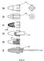
- FIGS 8a -f show different hinge pins according to the invention.
- Hinge pin 8a has a cylindrical base part, from the level of which protrude ribs 144 preventing rotation inside a lock bushing, and hinge pin 8b has on two sides bevelling 145 to prevent rotation inside the lock bushing.
- Hard tapered section 141B of hinge pin 8c is coated with soft elastomer, inside hinge pin 8d it has been molded or placed soft elastomer 410 as a spring element to replace a metal spring, inside hinge pin 8e is pre-installed metal spring 151, and hinge pin 8f is a hinge pin made of soft elastomer, which pin is supported by the straight extension of metal spring 152.
- Metal spring 152 also forms a hinge axle.
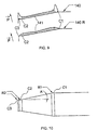
- Figure 9 shows the descriptor of the surface pressure, parallel to vector P and directed at tapered surface 141 of hinge pin 140 according to the invention in different parts of the surface during operating, and the descriptor of the corresponding surface pressure effecting on the different parts of surface 140R of the hinge pin, which hinge pin is rounded in the edges and continues after tapered surface 141 as a cylinder for a short distance.
- the figure illustrates how it is possible, by using rounded design, to reduce point loads directed at the hinge pin in comers C1, C2 and C3 and in this way to slow down the wear of the hinge pin and the forming of dust.
- Figure 10 shows the tapered end of a hinge pin according to Figure 8, rounded in the corners, comer C1 of which is rounded to radius of curvature R1 and comers C2 and C3 to radius of curvature R2.
- the figure also shows angle of taper A describing the steepness of the taper. The bigger the angle of taper, the shorter the taper naturally comes, the higher the pressure the taper is exposed to, and the faster the surface of the taper wears. Inversely, a gentle angle of taper results in a longer taper and better resistance to wear.
- Said corners C1, C2 and C3 can each have a radius of curvature of their own, but these can also be chosen individually, different from each other.
- FIG 11 shows a dual-taper construction according to a sixth embodiment of the invention, in which construction a hinged device comprises in one of its turning parts two tapered bowls 170 opening to opposite directions and hinge pins 140 tensioned against the bowls from outside using compressed springs.
- the hinge operates as explained earlier, except that in this case the friction surfaces have been doubled in a way shown in the figure.
- the figure does not show the lock bushings surrounding the hinge pins, which lock bushings can be e.g. alike the ones described above.
- Figure 12 shows a dual-taper construction according to a seventh embodiment of the invention.
- the dual-taper construction according to Figure 12 is alike the one shown in Figure 11, except that in this construction the bottoms of the tapered bowls are connected by a tunnel, in which there is draw-spring 150D pulling the hinge pins toward each other.
- Figure 13 shows a dual-taper construction according to an eighth embodiment of the invention.
- the tapered bowls open toward each other and between them there are two hinge pins 140 in lock bushing 111 common to both hinge pins, the pins being pushed away from each other against tapered bowls 170TW1 by compressed spring 150P.
- FIG 14 shows a dual-taper construction according to a ninth embodiment of the invention.
- both ends of the hinge pin have been tapered and axially moving tapered bowls 170TW2 are pressed against the ends of the hinge pin by springs.
- the advantage of a hinged electronic device according to the invention is the achieved small size and the high resistance to wear of the friction surfaces in relation to the size.
- the construction also is very simple compared with prior art and thus also well suited for both automatic and manual assembling.
- axle rod 160 which also acts as spring 150, and hinge pin 150.
- the hinge can be manufactured to be thin, because in a hinge according to the invention parts moving in relation to each other are needed in only two layers (hinge pin and tapered bowl), differently from e.g.
- a device in which device there is inside a tapered bushing a tapered friction piece and further inside it axle 12.
- the resistance to wear of a hinge according to the invention is finally determined by the thickness of the wear surfaces and by the play to be left in the tapered bowl in front of the hinge pin, because the spring pushes the hinge pin deeper and deeper and maintains a pressure between the friction surfaces within the limits set by the play of the hinge pin.
- a hinge according to the invention can be widely adjusted through choosing the materials of the friction surfaces, the tension of the spring, the angle of taper, the length of the taper and the diameter of the taper.
- a hinge according to the invention is particularly preferable in the case of e.g. communicator-type two-part mobile stations and PDA devices, but it is also applicable to e.g. a hinge between the display part and base part in portable computers.
Landscapes
- Engineering & Computer Science (AREA)
- Microelectronics & Electronic Packaging (AREA)
- Signal Processing (AREA)
- Pivots And Pivotal Connections (AREA)
- Telephone Set Structure (AREA)
- Casings For Electric Apparatus (AREA)
Applications Claiming Priority (2)
| Application Number | Priority Date | Filing Date | Title |
|---|---|---|---|
| FI982564A FI982564L (fi) | 1998-11-26 | 1998-11-26 | Saranoitu elektroninen laite |
| FI982564 | 1998-11-26 |
Publications (2)
| Publication Number | Publication Date |
|---|---|
| EP1005262A2 true EP1005262A2 (de) | 2000-05-31 |
| EP1005262A3 EP1005262A3 (de) | 2000-12-27 |
Family
ID=8552993
Family Applications (1)
| Application Number | Title | Priority Date | Filing Date |
|---|---|---|---|
| EP99121191A Withdrawn EP1005262A3 (de) | 1998-11-26 | 1999-10-22 | Klappbare elektronische Vorrichtung |
Country Status (3)
| Country | Link |
|---|---|
| US (1) | US6308377B1 (de) |
| EP (1) | EP1005262A3 (de) |
| FI (1) | FI982564L (de) |
Cited By (2)
| Publication number | Priority date | Publication date | Assignee | Title |
|---|---|---|---|---|
| EP1202532A3 (de) * | 2000-10-26 | 2003-05-21 | Samsung Electronics Co., Ltd. | Tragbare , klappbare Dateneingabevorrichtung mit konischer Scharniereinrichtung zur Verwendung in einem mobilen Kommunikationsendgerät |
| DE102017203800A1 (de) | 2017-03-08 | 2018-09-13 | Bayerische Motoren Werke Aktiengesellschaft | Verschwenkbare ladeeinrichtung zum induktiven laden eines energiespeichers eines kraftfahrzeugs |
Families Citing this family (13)
| Publication number | Priority date | Publication date | Assignee | Title |
|---|---|---|---|---|
| JP3517384B2 (ja) * | 2000-04-04 | 2004-04-12 | スガツネ工業株式会社 | ヒンジ装置 |
| US6747578B1 (en) * | 2001-04-27 | 2004-06-08 | Palmone, Inc. | Integrated removable functional faceplate for portable computer system |
| US7499282B1 (en) * | 2001-09-19 | 2009-03-03 | Palm, Inc. | Successively layered modular construction for a portable computer system |
| US6711781B2 (en) * | 2002-08-21 | 2004-03-30 | Lite-On Technology Corporation | Automatic releasing hinge |
| US7243892B2 (en) * | 2003-01-09 | 2007-07-17 | Csav, Inc. | Articulated mount |
| US20050091431A1 (en) * | 2003-10-23 | 2005-04-28 | Robert Olodort | Portable communication devices |
| USD595723S1 (en) | 2007-11-09 | 2009-07-07 | Milestone Av Technologies Llc | Pivot arm assembly for mounting an electronic display |
| TWI452211B (zh) * | 2011-11-14 | 2014-09-11 | Avision Inc | 自動閉合式樞紐器及使用其之掀蓋式電子裝置 |
| JP6142636B2 (ja) * | 2013-04-10 | 2017-07-12 | 富士通株式会社 | ヒンジ装置 |
| KR20190041065A (ko) * | 2017-10-12 | 2019-04-22 | 에이치피프린팅코리아 유한회사 | 힌지 장치 |
| CN111101789B (zh) * | 2019-11-13 | 2021-03-16 | 中国电子科技集团公司第十四研究所 | 一种单点控制多点联动的高精度快速锁紧机构 |
| KR102920644B1 (ko) * | 2020-06-19 | 2026-02-02 | 삼성전자주식회사 | 전자 장치 |
| TWI849634B (zh) * | 2022-12-21 | 2024-07-21 | 華碩電腦股份有限公司 | 與轉軸天線共構之電子裝置及其轉軸天線 |
Family Cites Families (11)
| Publication number | Priority date | Publication date | Assignee | Title |
|---|---|---|---|---|
| FR2582845B1 (fr) * | 1985-06-03 | 1987-08-28 | Selmer Cie Henri | Guide d'axe d'articulation notamment pour instrument de musique |
| US4620344A (en) | 1985-08-15 | 1986-11-04 | General Electric Company | Friction applying assembly |
| US5075929A (en) | 1990-07-02 | 1991-12-31 | Industrial Technology Research Institute | Hinge mechanism for a portable apparatus |
| FR2669762A1 (fr) * | 1990-11-27 | 1992-05-29 | Weril Instr Musicais Ltda | Glissiere d'articulation pour mecanisme des clefs d'un instrument de musique. |
| US5274882A (en) * | 1992-03-03 | 1994-01-04 | Ericsson Ge Mobile Communications Inc. | Hinge mechanism |
| GB2286011A (en) | 1994-01-26 | 1995-08-02 | David Southward | Friction hinge |
| US5628089A (en) * | 1995-05-18 | 1997-05-13 | Motorola, Inc. | Radiotelephone having a self contained hinge |
| FI961587L (fi) * | 1996-04-11 | 1997-10-12 | Nokia Mobile Phones Ltd | Saranamekanismi kokoontaitettavan laitteen kahden osan kiinnittämiseksi kääntyvästi toisiinsa |
| US5715576A (en) * | 1997-02-04 | 1998-02-10 | Liu; Tai-Sheng | Hinge device for coupling two rotatable members |
| JPH10252739A (ja) * | 1997-03-07 | 1998-09-22 | Sutoroberii Corp:Kk | ヒンジ装置 |
| US6101676A (en) * | 1998-01-27 | 2000-08-15 | Dell Usa, L.P. | Adjustable clutch hinge assembly for portable computer |
-
1998
- 1998-11-26 FI FI982564A patent/FI982564L/fi unknown
-
1999
- 1999-10-22 EP EP99121191A patent/EP1005262A3/de not_active Withdrawn
- 1999-11-19 US US09/444,286 patent/US6308377B1/en not_active Expired - Fee Related
Cited By (3)
| Publication number | Priority date | Publication date | Assignee | Title |
|---|---|---|---|---|
| EP1202532A3 (de) * | 2000-10-26 | 2003-05-21 | Samsung Electronics Co., Ltd. | Tragbare , klappbare Dateneingabevorrichtung mit konischer Scharniereinrichtung zur Verwendung in einem mobilen Kommunikationsendgerät |
| US6625011B2 (en) | 2000-10-26 | 2003-09-23 | Samsung Electronics Co., Ltd. | Portable, foldable data input device with conical hinge means for use in a mobile communication terminal |
| DE102017203800A1 (de) | 2017-03-08 | 2018-09-13 | Bayerische Motoren Werke Aktiengesellschaft | Verschwenkbare ladeeinrichtung zum induktiven laden eines energiespeichers eines kraftfahrzeugs |
Also Published As
| Publication number | Publication date |
|---|---|
| FI982564A0 (fi) | 1998-11-26 |
| FI982564A7 (fi) | 2000-05-27 |
| EP1005262A3 (de) | 2000-12-27 |
| FI982564L (fi) | 2000-05-27 |
| US6308377B1 (en) | 2001-10-30 |
Similar Documents
| Publication | Publication Date | Title |
|---|---|---|
| US6308377B1 (en) | Hinged electronic device | |
| CN207009790U (zh) | 耳机 | |
| US6115886A (en) | Hinge apparatus | |
| CN100439789C (zh) | 计算机控制的显示设备 | |
| US9201453B2 (en) | Self-retracting connector for docking device | |
| US7218510B2 (en) | Computer controlled display device | |
| US8432677B2 (en) | Hinge assembly for foldable electronic device | |
| US8245354B2 (en) | Hinge assembly for foldable electronic device | |
| US20040233623A1 (en) | Computer controlled display device | |
| US9641212B1 (en) | Protective shell with supporting function | |
| US20100071159A1 (en) | Hinge type cover opening and closing device for mobile phone | |
| US7822447B2 (en) | Push rod and sliding type portable terminal having the same | |
| KR100989090B1 (ko) | 책상 매립형 멀티콘센트 | |
| US8370994B2 (en) | Automatically opening hinge assembly for portable electronic devices | |
| US20050088812A1 (en) | Computer controlled display device | |
| CN102459792A (zh) | 用于将翼扇绕铰链轴线铰接地与框架连接的铰链 | |
| JP2009174716A (ja) | ヒンジ構造及び、該ヒンジ構造を用いる携帯電子装置 | |
| EP1914963A1 (de) | Mehrfach Drehfeder und halbautomatische Schiebevorrichtung damit | |
| US20090145337A1 (en) | Slidable hinge | |
| US20060236504A1 (en) | Hinge | |
| KR100972574B1 (ko) | 휴대단말기용 댐핑 힌지장치 | |
| US20220059981A1 (en) | Crimping hand tool | |
| US20100037429A1 (en) | Hinge assembly | |
| US7233292B2 (en) | Antenna device having rotatable structure | |
| US8593794B2 (en) | Hinge assembly for foldable electronic device |
Legal Events
| Date | Code | Title | Description |
|---|---|---|---|
| PUAI | Public reference made under article 153(3) epc to a published international application that has entered the european phase |
Free format text: ORIGINAL CODE: 0009012 |
|
| AK | Designated contracting states |
Kind code of ref document: A2 Designated state(s): DE FR GB NL |
|
| AX | Request for extension of the european patent |
Free format text: AL;LT;LV;MK;RO;SI |
|
| PUAL | Search report despatched |
Free format text: ORIGINAL CODE: 0009013 |
|
| AK | Designated contracting states |
Kind code of ref document: A3 Designated state(s): AT BE CH CY DE DK ES FI FR GB GR IE IT LI LU MC NL PT SE |
|
| AX | Request for extension of the european patent |
Free format text: AL;LT;LV;MK;RO;SI |
|
| RIC1 | Information provided on ipc code assigned before grant |
Free format text: 7H 05K 5/02 A, 7H 04M 1/02 B, 7G 06F 1/16 B, 7E 05D 11/10 B |
|
| 17P | Request for examination filed |
Effective date: 20010627 |
|
| AKX | Designation fees paid |
Free format text: DE FR GB NL |
|
| RAP1 | Party data changed (applicant data changed or rights of an application transferred) |
Owner name: NOKIA CORPORATION |
|
| STAA | Information on the status of an ep patent application or granted ep patent |
Free format text: STATUS: THE APPLICATION IS DEEMED TO BE WITHDRAWN |
|
| 18D | Application deemed to be withdrawn |
Effective date: 20060503 |