EP1005607B1 - Verfahren und anordnung für die elektronisch geregelte förderung und zumessung kryogener medien bei flugtriebwerken - Google Patents
Verfahren und anordnung für die elektronisch geregelte förderung und zumessung kryogener medien bei flugtriebwerken Download PDFInfo
- Publication number
- EP1005607B1 EP1005607B1 EP98946381A EP98946381A EP1005607B1 EP 1005607 B1 EP1005607 B1 EP 1005607B1 EP 98946381 A EP98946381 A EP 98946381A EP 98946381 A EP98946381 A EP 98946381A EP 1005607 B1 EP1005607 B1 EP 1005607B1
- Authority
- EP
- European Patent Office
- Prior art keywords
- piston
- pump
- hydraulic
- linear motor
- regulator
- Prior art date
- Legal status (The legal status is an assumption and is not a legal conclusion. Google has not performed a legal analysis and makes no representation as to the accuracy of the status listed.)
- Expired - Lifetime
Links
- 238000000034 method Methods 0.000 title claims description 10
- 239000000446 fuel Substances 0.000 claims description 30
- UFHFLCQGNIYNRP-UHFFFAOYSA-N Hydrogen Chemical compound [H][H] UFHFLCQGNIYNRP-UHFFFAOYSA-N 0.000 claims description 8
- 239000001257 hydrogen Substances 0.000 claims description 8
- 229910052739 hydrogen Inorganic materials 0.000 claims description 8
- 238000009413 insulation Methods 0.000 claims description 8
- 238000006073 displacement reaction Methods 0.000 claims description 7
- 238000002347 injection Methods 0.000 claims description 7
- 239000007924 injection Substances 0.000 claims description 7
- 239000007788 liquid Substances 0.000 claims description 7
- 229920002430 Fibre-reinforced plastic Polymers 0.000 claims description 2
- 239000011151 fibre-reinforced plastic Substances 0.000 claims description 2
- 239000000463 material Substances 0.000 claims 2
- 239000012530 fluid Substances 0.000 description 6
- IJGRMHOSHXDMSA-UHFFFAOYSA-N Atomic nitrogen Chemical compound N#N IJGRMHOSHXDMSA-UHFFFAOYSA-N 0.000 description 2
- 230000001133 acceleration Effects 0.000 description 2
- 238000002485 combustion reaction Methods 0.000 description 2
- 238000005516 engineering process Methods 0.000 description 2
- 238000001704 evaporation Methods 0.000 description 2
- 230000008020 evaporation Effects 0.000 description 2
- 239000002828 fuel tank Substances 0.000 description 2
- 239000003350 kerosene Substances 0.000 description 2
- 238000004519 manufacturing process Methods 0.000 description 2
- VNWKTOKETHGBQD-UHFFFAOYSA-N methane Chemical compound C VNWKTOKETHGBQD-UHFFFAOYSA-N 0.000 description 2
- 230000010363 phase shift Effects 0.000 description 2
- 238000007789 sealing Methods 0.000 description 2
- 206010053615 Thermal burn Diseases 0.000 description 1
- 230000006866 deterioration Effects 0.000 description 1
- 238000000605 extraction Methods 0.000 description 1
- 239000007789 gas Substances 0.000 description 1
- 238000009499 grossing Methods 0.000 description 1
- 239000001307 helium Substances 0.000 description 1
- 229910052734 helium Inorganic materials 0.000 description 1
- SWQJXJOGLNCZEY-UHFFFAOYSA-N helium atom Chemical compound [He] SWQJXJOGLNCZEY-UHFFFAOYSA-N 0.000 description 1
- 238000002955 isolation Methods 0.000 description 1
- 238000012423 maintenance Methods 0.000 description 1
- 239000003345 natural gas Substances 0.000 description 1
- 229910052757 nitrogen Inorganic materials 0.000 description 1
- 230000001105 regulatory effect Effects 0.000 description 1
- 230000033764 rhythmic process Effects 0.000 description 1
- 230000007704 transition Effects 0.000 description 1
Images
Classifications
-
- F—MECHANICAL ENGINEERING; LIGHTING; HEATING; WEAPONS; BLASTING
- F04—POSITIVE - DISPLACEMENT MACHINES FOR LIQUIDS; PUMPS FOR LIQUIDS OR ELASTIC FLUIDS
- F04B—POSITIVE-DISPLACEMENT MACHINES FOR LIQUIDS; PUMPS
- F04B15/00—Pumps adapted to handle specific fluids, e.g. by selection of specific materials for pumps or pump parts
- F04B15/06—Pumps adapted to handle specific fluids, e.g. by selection of specific materials for pumps or pump parts for liquids near their boiling point, e.g. under subnormal pressure
- F04B15/08—Pumps adapted to handle specific fluids, e.g. by selection of specific materials for pumps or pump parts for liquids near their boiling point, e.g. under subnormal pressure the liquids having low boiling points
-
- F—MECHANICAL ENGINEERING; LIGHTING; HEATING; WEAPONS; BLASTING
- F02—COMBUSTION ENGINES; HOT-GAS OR COMBUSTION-PRODUCT ENGINE PLANTS
- F02C—GAS-TURBINE PLANTS; AIR INTAKES FOR JET-PROPULSION PLANTS; CONTROLLING FUEL SUPPLY IN AIR-BREATHING JET-PROPULSION PLANTS
- F02C3/00—Gas-turbine plants characterised by the use of combustion products as the working fluid
- F02C3/20—Gas-turbine plants characterised by the use of combustion products as the working fluid using a special fuel, oxidant, or dilution fluid to generate the combustion products
- F02C3/22—Gas-turbine plants characterised by the use of combustion products as the working fluid using a special fuel, oxidant, or dilution fluid to generate the combustion products the fuel or oxidant being gaseous at standard temperature and pressure
-
- F—MECHANICAL ENGINEERING; LIGHTING; HEATING; WEAPONS; BLASTING
- F02—COMBUSTION ENGINES; HOT-GAS OR COMBUSTION-PRODUCT ENGINE PLANTS
- F02C—GAS-TURBINE PLANTS; AIR INTAKES FOR JET-PROPULSION PLANTS; CONTROLLING FUEL SUPPLY IN AIR-BREATHING JET-PROPULSION PLANTS
- F02C7/00—Features, components parts, details or accessories, not provided for in, or of interest apart form groups F02C1/00 - F02C6/00; Air intakes for jet-propulsion plants
- F02C7/22—Fuel supply systems
-
- F—MECHANICAL ENGINEERING; LIGHTING; HEATING; WEAPONS; BLASTING
- F02—COMBUSTION ENGINES; HOT-GAS OR COMBUSTION-PRODUCT ENGINE PLANTS
- F02C—GAS-TURBINE PLANTS; AIR INTAKES FOR JET-PROPULSION PLANTS; CONTROLLING FUEL SUPPLY IN AIR-BREATHING JET-PROPULSION PLANTS
- F02C9/00—Controlling gas-turbine plants; Controlling fuel supply in air- breathing jet-propulsion plants
- F02C9/26—Control of fuel supply
- F02C9/30—Control of fuel supply characterised by variable fuel pump output
-
- F—MECHANICAL ENGINEERING; LIGHTING; HEATING; WEAPONS; BLASTING
- F04—POSITIVE - DISPLACEMENT MACHINES FOR LIQUIDS; PUMPS FOR LIQUIDS OR ELASTIC FLUIDS
- F04B—POSITIVE-DISPLACEMENT MACHINES FOR LIQUIDS; PUMPS
- F04B9/00—Piston machines or pumps characterised by the driving or driven means to or from their working members
- F04B9/08—Piston machines or pumps characterised by the driving or driven means to or from their working members the means being fluid
- F04B9/10—Piston machines or pumps characterised by the driving or driven means to or from their working members the means being fluid the fluid being liquid
- F04B9/109—Piston machines or pumps characterised by the driving or driven means to or from their working members the means being fluid the fluid being liquid having plural pumping chambers
- F04B9/111—Piston machines or pumps characterised by the driving or driven means to or from their working members the means being fluid the fluid being liquid having plural pumping chambers with two mechanically connected pumping members
- F04B9/113—Piston machines or pumps characterised by the driving or driven means to or from their working members the means being fluid the fluid being liquid having plural pumping chambers with two mechanically connected pumping members reciprocating movement of the pumping members being obtained by a double-acting liquid motor
-
- F—MECHANICAL ENGINEERING; LIGHTING; HEATING; WEAPONS; BLASTING
- F04—POSITIVE - DISPLACEMENT MACHINES FOR LIQUIDS; PUMPS FOR LIQUIDS OR ELASTIC FLUIDS
- F04B—POSITIVE-DISPLACEMENT MACHINES FOR LIQUIDS; PUMPS
- F04B15/00—Pumps adapted to handle specific fluids, e.g. by selection of specific materials for pumps or pump parts
- F04B15/06—Pumps adapted to handle specific fluids, e.g. by selection of specific materials for pumps or pump parts for liquids near their boiling point, e.g. under subnormal pressure
- F04B15/08—Pumps adapted to handle specific fluids, e.g. by selection of specific materials for pumps or pump parts for liquids near their boiling point, e.g. under subnormal pressure the liquids having low boiling points
- F04B2015/081—Liquefied gases
- F04B2015/0822—Hydrogen
-
- F—MECHANICAL ENGINEERING; LIGHTING; HEATING; WEAPONS; BLASTING
- F04—POSITIVE - DISPLACEMENT MACHINES FOR LIQUIDS; PUMPS FOR LIQUIDS OR ELASTIC FLUIDS
- F04B—POSITIVE-DISPLACEMENT MACHINES FOR LIQUIDS; PUMPS
- F04B2203/00—Motor parameters
- F04B2203/09—Motor parameters of linear hydraulic motors
-
- F—MECHANICAL ENGINEERING; LIGHTING; HEATING; WEAPONS; BLASTING
- F04—POSITIVE - DISPLACEMENT MACHINES FOR LIQUIDS; PUMPS FOR LIQUIDS OR ELASTIC FLUIDS
- F04B—POSITIVE-DISPLACEMENT MACHINES FOR LIQUIDS; PUMPS
- F04B2203/00—Motor parameters
- F04B2203/09—Motor parameters of linear hydraulic motors
- F04B2203/0903—Position of the driving piston
Definitions
- the invention relates to a method and the arrangement required for implementation Components for electronically controlled conveyance and metering of cryogenic media, such as. Liquid hydrogen at -250 ° C, for aircraft engines and for industrial applications.
- kerosene is used as fuel becomes.
- the kerosene is usually supplied via a gear pump to avoid of cavitation often has a centrifugal pump as a preliminary stage, promoted and via a separate metering valve supplied to the combustion chamber of the engine. Because the pump over the auxiliary gear is driven directly by the engine, it should be dimensioned so that the maximum occurring at all engine rotor speeds Can cover fuel requirements for rotor acceleration when flying close to the ground. In all other operating situations, it then continuously promotes a surplus that either is returned to the fuel tank or to the pump inlet.
- cryogenic fuels e.g. Liquid hydrogen is one such recirculation not possible, as this creates vapor bubbles at the pump inlet (risk of cavitation) or would lead to unacceptable evaporation losses in the fuel tank.
- a controllable, throughput-variable fuel delivery is for cryogenic media, each only the fuel actually required by the engine (without excess) provides, inevitable.
- This engine uses one from rocket technology 2-stage turbo centrifugal pump used.
- the pump will for regulating the delivery volume, realized via speed variation, powered by compressed air from the engine.
- the metering of the Fuel is supplied via a gas metering valve, which is downstream of the Heat exchanger / evaporator is installed.
- To control the Helium is used in cryo valves.
- the building principles described above have several Disadvantages:
- the high number of components means a high number Complexity of the overall system, because of the very demanding high operational reliability is undesirable.
- the isolation option the centrifugal pump is inherently bad.
- Another disadvantage is that for the pump and for the metering valve one control loop each must be set up, the functional are coupled.
- the centrifugal pump because of the large gap influence in the production of liquid hydrogen poor efficiency. I should also mention that Engine efficiency deterioration due to bleed air extraction for the pump drive.
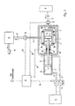
- the cryogenic fuel is transferred from the cryotank 6 to the injection nozzles by a piston pump 18 promoted.
- the pump piston 1 of the cryopump is driven by a hydraulic piston 7 coupled by means of an axially movable piston rod 4.
- the hydraulic pressure is provided by a hydraulic supply unit 13; the hydraulic flow to generate the lifting movements of the hydraulic piston 7 is from a Controller 14, preferably of digital design, controlled by means of servo valve 12.
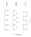
- a double-acting pump can be used as the piston pump, but one The delivery throughput drops when the pump piston 1 passes through the reversal point must be accepted (Figure 2a).
- two single-acting pump systems can be operated in parallel with a phase shift of 180 ° between the work cycles of the two pump pistons 1 become. This compensates for the pressure drop in the piston reversal points one and the pressure increase of the other piston pump, so that in total a largely constant flow rate and constant delivery pressure can be achieved (Figure 2c).
- Another way of smoothing the pressure profile is by using reach two double-acting pumps that work 90 ° out of phase (Fig 2 B). The remaining small, short-term pressure drop in the respective piston reversal points is determined by the storage volume of the downstream heat exchanger 16 largely balanced. Also a large number of parallel ones Pump as two and other than the above phase shift angles are part of the inventive scope of claims.
- the digital control system can detect faults in two or more channels and the electrical one Parts of the system are designed to be redundant one or more times.
- the pump for the cryogenic medium consists of a pump piston 1, which is in a Pump housing 2 is running, its working spaces 9 with the cryogenic to be pumped Are filled with fuel.
- the pump housing 2 of the cryopump is surrounded by a Insulation housing 10, the space between the insulation housing 10 and the pump housing 2 of the cryopump is designed as an insulation space 3. It is preferably provide insulation by vacuum.
- the pump piston 1 is by means of a axially movable piston rod 4 with the hydraulic piston 7 providing the drive connected. This runs in the hydraulic housing 11, the working spaces 8 on both sides of the hydraulic piston 7 are connected to the hydraulic lines 21 so that the hydraulic piston 7 also functionally with the hydraulic fluid in the respective reversal points can be applied.
- the hydraulic pressure is from the hydraulic supply unit 13 (known technology) is provided.
- the control of the hydraulic fluid according to strength and direction (the fluid in the hydraulic lines 21 changes its direction of flow constantly in accordance with the stroke movement to be given to the hydraulic piston 7) is carried out by the controller 14, which is preferably of a digital design
- the controller 14 controls the hydraulic servo valve 12: controlled the respective flow direction of the hydraulic fluid, the flow direction reversal and the flow rate with which the lifting speed of the hydraulic piston 7 is determined.
- the controller 14 continuously needs information about the current position of the hydraulic piston 7 in the hydraulic housing 11 and its speed. These are measured by means of the electrical displacement and speed sensor 23 and continuously supplied to the controller 14 via the measured value line 24.
- the way and Velocity pickup 23 can be integrated into the guide piece 25 what compact design allowed.
- the regulator 14 also controls the hydraulic supply unit 13 and provides error messages in the event of failure or incorrect behavior of individual components.
- the pump piston 1 sucks according to the hydraulic piston 7 predetermined rhythm, the cryogenic medium from the tank 6 via the suction line 5 in the work rooms 9, it presses from there via the pressure lines 17 and the heat exchanger 16 in the injection nozzles 18.
- check valves 26 are provided in the pressure lines.
- On Electronic controller 14 controls the movement of the hydraulic piston so that one if possible uniform flow is achieved.
- Shut-off valves 22 and 15 can be provided by the controller 14 via the lines Shut-off valve 20 are controlled and checked. Its purpose: after switching off of the engine, the shut-off valves 22 and 15 prevent fuel from running on.
Landscapes
- Engineering & Computer Science (AREA)
- Mechanical Engineering (AREA)
- General Engineering & Computer Science (AREA)
- Chemical & Material Sciences (AREA)
- Combustion & Propulsion (AREA)
- Reciprocating Pumps (AREA)
Description
- Figur 1
- zeigt schematisch die Anordnung der Bauelemente für die kryogene Kraftstoff-Förderung und Zumessung, hier mit einer doppeltwirkenden Kryopumpe.
- Figur 2a
- zeigt das Kraftstoffdurchsatzprofil über der Zeitachse für eine doppeltwirkende Kryopumpe,
- Figur 2b
- zeigt das Profil für zweidoppeltwirkende Kryopumpen, die um 90° phasenverschoben
arbeiten,
und - Figur 2c
- zeigt das Profil von zwei einfachwirkenden Kryopumpen, die um 180° phasenverschoben arbeiten.
- 1.
- Pumpenkolben
- 2.
- Pumpengehäuse
- 3.
- Isolationsraum
- 4.
- Kolbenstange
- 5.
- Ansaugleitung
- 6.
- Kryotank
- 7.
- Hydraulikkolben
- 8.
- Arbeitsräume Hydraulikantrieb
- 9.
- Arbeitsräume Kryopumpe
- 10.
- Isolationsgehäuse
- 11.
- Hydraulikgehäuse
- 12.
- Hydraulik-Servoventile
- 13.
- Hydraulik-Versorgungseinheit
- 14.
- Regler
- 15.
- Absperrventil (druckseitig)
- 16.
- Wärmetauscher
- 17.
- Druckleitung Kryomedium
- 18.
- Verdampferdüsen
- 19.
- Leitung Regelungssignale Servoventile
- 20.
- Leitung Absperrventil
- 21.
- Hydraulikleitungen
- 22.
- Absperrventil (saugseitig)
- 23.
- Weg- und Geschwindigkeitsaufnehmer
- 24.
- Messwerteleitung
- 25.
- Führungsstück
- 26.
- Rückschlagventil
Claims (10)
- Verfahren für die Förderung und Zumessung kryogener Treibstoffe vorzugsweise bei Flugtriebwerken mit folgenden Merkmalen:gekennzeichnet durchFördern des kryogenen Treibstoffes, beispielsweise flüssiger Wasserstoff bei minus 250 °C, aus einem Tank (6) zur Einspritzdüse (18) mittels einer Kolbenpumpe,Antreiben der Kolbenpumpe mittels eines hydraulischen Linearmotors, wobei die Kolbenpumpe für die Förderung des kryogenen Treibstoffs und der sie antreibende hydraulische Linearmotor eine gekoppelte Einheit bilden,
folgende Merkmale:Steuern des hydraulischen Linearmotors und damit des Kraftstoffdurchsatzes nach Menge und Förderdruck durch einen programmgesteuerten Regler (14), vorzugsweise digitaler Bautechnik, wobei der Regler (14) den hydraulischen Linearmotor über ein Servoventil (12) derart steuert, dass zwischen den Bereichen der Kolbenumkehrbewegung eine konstante Geschwindigkeit eines Hydraulikkolbens (7) und damit eines Pumpenkolbens (1) für einen konstanten Kraftstoffdurchsatz über der Zeitachse erreicht wird, und eine momentane Position des Hydraulikkolbens (7) sowie seine jeweilige Geschwindigkeit laufend mittels eines elektrischen Weg- und Geschwindigkeitsaufnehmers (23) an einer Kolbenstange (4) erhoben und dem Regler (14) zugeleitet werden. - Verfahren gemäß Anspruch 1,
gekennzeichnet dadurch, dass
als Kolbenpumpe eine Kolbenpumpe von doppelt wirkender Bauart eingesetzt wird. - Verfahren gemäß Anspruch 2,
gekennzeichnet dadurch, dass
zur Minimierung der Druck- und Durchsatzschwankungen des kryogenen Treibstoffes zwei doppelt wirkende, parallel mit 90° Phasenverschiebung arbeitenden Kolbenpumpen eingesetzt werden. - Verfahren gemäß Anspruch 1,
gekennzeichnet dadurch, dass
zur Minimierung der Druck- und Durchsatzschwankungen des kryogenen Treibstoffes zwei einfach wirkende, parallel mit 180° Phasenverschiebung arbeitende Kolbenpumpen eingesetzt werden. - Anordnung für die Förderung und Zumessung kryogener Treibstoffe vorzugsweise bei Flugtriebwerken mit folgenden Merkmalen:gekennzeichnet durcheiner Kolbenpumpe zur Förderung des kryogenen Treibstoffes aus einem Kryotank (6) zu Einspritzdüsen (18), wobei die Kolbenpumpe aus einem Pumpenkolben (1), einem Pumpengehäuse (2), einer Kolbenstange (4) sowie saugseitigen und druckseitigen Leitungen (5) und (16) für das Kryomedium besteht,einem hydraulischen Linearmotor zum Antrieb des Pumpenkolbens (1) und der Kolbenstange (4), wobei der Linearmotor aus einem Hydraulikkolben (7) sowie einem Hydraulikgehäuse (11), einer Hydraulik-Versorgungseinheit (13) und Hydraulikleitungen (21) besteht, und der Pumpenkolben (1), der Hydraulikkolben (7) und die Kolbenstange (4) als starr verbundene, axial bewegbare Einheit ausgebildet sind,
folgende Merkmale:einen Regler (14), vorzugsweise digitaler Bauart, zur Steuerung des hydraulischen Linearmotors, wobei der Regler (14) ein Programm zur Steuerung eines Hydraulik-Servoventils (12) sowie zur Schaltung eines in der Ansaugleitung (5) angeordneten Absperrventils (22) und eines in der Druckleitung (17) angeordneten Absperrventils (15) enthält,einen elektrischen Weg- und Geschwindigkeitsaufnehmer (23), der derart ausgebildet ist, dass dessen Signale bezüglich Position und Geschwindigkeit des Hydraulikkolbens (7) und damit des Pumpenkolbens (1) über eine Messwerteleitung (24) dem Regler (14) zugeführt werden, wobei der Weg- und Geschwindigkeitsaufnehmer (23) vorzugsweise im Führungsstück (25) integriert ist,ein Isolationsgehäuse (10), welches das Pumpengehäuse (2) derart umgibt, dass zwischen beiden eine den Wärmefluss minimierende Isolierung, vorzugsweise Vakuum, vorhanden ist, undeinen Wärmetauscher (16) zwischen der Kolbenpumpe und den Einspritzdüsen (18). - Anordnung gemäß Anspruch 5,
gekennzeichnet dadurch, dass
die Kolbenstange als Rohr ausgebildet ist und aus einem Material mit niedriger Wärmeleitung besteht. - Anordnung gemäß Anspruch 5,
gekennzeichnet dadurch, dass
das Führungsstück (25) aus Material mit niedriger Wärmeleitfähigkeit wie z.B. faserverstärkten Kunststoffen besteht. - Anordnung gemäß Anspruch 5,
gekennzeichnet dadurch, dass
zur Minimierung von Druck- und Durchsatzschwankungen zwei doppelt wirkende, parallel arbeitende Kolbenpumpen mit jeweils eigenem Linearmotor und Servoventil vorhanden sind, die mit einer 90° Phasenverschiebung betrieben werden. - Anordnung gemäß Anspruch 5,
gekennzeichnet dadurch, dass
zur Minimierung von Druck- und Durchsatzschwankungen zwei einfach wirkende, parallel arbeitende Kolbenpumpen mit 180° Phasenverschiebung vorhanden sind. - Anordnung für die Förderung und Zumessung kryogener Treibstoffe vorzugsweise bei Flugtriebwerken mit folgenden Merkmalen:gekennzeichnet durcheiner Kolbenpumpe zur Förderung des kryogenen Treibstoffes aus einem Kryotank (6) zur Einspritzdüse (18), wobei die Kolbenpumpe aus einem Pumpenkolben (1), einem Pumpengehäuse (2), einer Kolbenstange (4), sowie saugseitigen und druckseitigen Leitungen (5) und (17) für das Kryomedium besteht,einem Linearmotor zum Antrieb des Pumpenkolbens (1) und der Kolbenstange (4), wobei der Linearmotor aus einem Kolben (7) sowie einem Gehäuse (11), einer Versorgungseinheit (13) und Leitungen (21) besteht, wobei der Pumpenkolben (1), der Kolben (7) und die Kolbenstange (4) als starr verbundene axial bewegbare Einheit ausgebildet sind,
folgende Merkmale:einen elektrischen Linearmotor,einen Regler (14), vorzugsweise digitaler Bauart, zur Steuerung des elektrischen Linearmotors, wobei der Regler (14) ein Programm zur Steuerung enthält,einem elektrischen Weg- und Geschwindigkeitsaufnehmer (23), der derart ausgebildet ist, dass dessen Signale bezüglich Position und Geschwindigkeit des Kolbens (7) und damit des Pumpenkolbens (1) über eine Messwerteleitung (24) dem Regler (14) zugeführt werden, wobei der Weg- und Geschwindigkeitsaufnehmer (23) vorzugsweise im Führungsstück (27) integriert ist,ein Isolationsgehäuse (10), welches das Pumpengehäuse (2) derart umgibt, dass zwischen beiden eine den Wärmefluss minimierende Isolierung, vorzugsweise Vakuum, vorhanden ist, undein Wärmetauscher (16) zwischen der Kolbenpumpe und den Einspritzdüsen (18).
Applications Claiming Priority (3)
| Application Number | Priority Date | Filing Date | Title |
|---|---|---|---|
| DE19736337 | 1997-08-21 | ||
| DE19736337A DE19736337C2 (de) | 1997-08-21 | 1997-08-21 | Anordnung für die elektronisch geregelte Förderung und Zumessung kryogener Medien bei Flugtriebwerken |
| PCT/EP1998/005267 WO1999010640A1 (de) | 1997-08-21 | 1998-08-19 | Verfahren und anordnung für die elektronisch geregelte förderung und zumessung kryogener medien bei flugtriebwerken |
Publications (2)
| Publication Number | Publication Date |
|---|---|
| EP1005607A1 EP1005607A1 (de) | 2000-06-07 |
| EP1005607B1 true EP1005607B1 (de) | 2003-06-25 |
Family
ID=7839685
Family Applications (1)
| Application Number | Title | Priority Date | Filing Date |
|---|---|---|---|
| EP98946381A Expired - Lifetime EP1005607B1 (de) | 1997-08-21 | 1998-08-19 | Verfahren und anordnung für die elektronisch geregelte förderung und zumessung kryogener medien bei flugtriebwerken |
Country Status (3)
| Country | Link |
|---|---|
| EP (1) | EP1005607B1 (de) |
| DE (2) | DE19736337C2 (de) |
| WO (1) | WO1999010640A1 (de) |
Cited By (7)
| Publication number | Priority date | Publication date | Assignee | Title |
|---|---|---|---|---|
| CN101205954B (zh) * | 2006-12-14 | 2012-11-14 | 罗伯特.博世有限公司 | 用于操作离合器的装置和方法 |
| WO2018093385A1 (en) * | 2016-11-21 | 2018-05-24 | Halliburton Energy Services, Inc. | Cylinder pump systems and methods for pumping and measuring fluids |
| EP4431789A1 (de) * | 2023-03-13 | 2024-09-18 | Linde GmbH | Verfahren und vorrichtung zur speicherung eines flüssigen kryogenen mediums |
| WO2026013156A1 (en) * | 2024-07-09 | 2026-01-15 | Phinia Delphi Luxembourg Sarl | Compressor system |
| FR3167407A1 (fr) * | 2024-10-10 | 2026-04-17 | Safran Aircraft Engines | Dispositif de régulation de la variation de pression pour système d’alimentation en hydrogène d’une turbomachine |
| EP4733563A1 (de) * | 2024-10-25 | 2026-04-29 | Pratt & Whitney Canada Corp. | Systeme und verfahren zum betrieb eines flugzeugmotors unter verwendung mehrerer kraftstoffarten |
| EP4733564A1 (de) * | 2024-10-25 | 2026-04-29 | Pratt & Whitney Canada Corp. | Systeme und verfahren zum betrieb eines flugzeugmotors unter verwendung mehrerer kraftstoffarten |
Families Citing this family (14)
| Publication number | Priority date | Publication date | Assignee | Title |
|---|---|---|---|---|
| US6659730B2 (en) * | 1997-11-07 | 2003-12-09 | Westport Research Inc. | High pressure pump system for supplying a cryogenic fluid from a storage tank |
| WO2010066069A1 (zh) * | 2008-12-12 | 2010-06-17 | Yu Chun Kwan | 流体动力装置 |
| DE102010025243B4 (de) * | 2010-06-26 | 2014-04-10 | Audi Ag | Kraftwagen mit einer Lamellenkupplung |
| FR2965313B1 (fr) * | 2010-09-29 | 2012-09-07 | Exel Ind | Procede, dispositif et moyen d'entrainement de pompe a double effet a mouvement lineaire alternatif |
| EP2604840A1 (de) * | 2011-12-16 | 2013-06-19 | Astrium GmbH | Förder-Aggregat für kryogene Flüssigkeiten |
| US9915251B2 (en) | 2015-03-26 | 2018-03-13 | Caterpillar Inc. | Fuel system having serially arranged in-tank pumps |
| DK179219B1 (en) * | 2016-05-26 | 2018-02-12 | Man Diesel & Turbo Filial Af Man Diesel & Turbo Se Tyskland | Fuel or lubrication pump for a large two-stroke compression-ignited internal combustion engine |
| DE102016210731A1 (de) * | 2016-06-16 | 2017-12-21 | Robert Bosch Gmbh | Förderpumpe für kryogene Kraftstoffe |
| DE102017219224A1 (de) * | 2017-10-26 | 2019-05-02 | Robert Bosch Gmbh | Kraftstofffördereinrichtung für kryogene Kraftstoffe, Verfahren zum Betreiben einer Kraftstofffördereinrichtung für kryogene Kraftstoffe |
| DE102017222202A1 (de) * | 2017-12-07 | 2019-06-13 | Robert Bosch Gmbh | Kraftstofffördereinrichtung für kryogene Kraftstoffe |
| DE102017222382A1 (de) * | 2017-12-11 | 2019-06-13 | Robert Bosch Gmbh | Verfahren zum Betreiben einer Kolbenpumpe, Kolbenpumpe |
| GB2581164A (en) * | 2019-02-06 | 2020-08-12 | Mhwirth Gmbh | Fluid pump, pump assembly and method of pumping fluid |
| EP4336027A1 (de) | 2022-09-09 | 2024-03-13 | General Electric Company | Durchflussmesskraftstoffsysteme und zugehörige verfahren |
| US20250320862A1 (en) * | 2024-04-15 | 2025-10-16 | Robert Bosch Gmbh | Cryogenic pump for hydrogen fueling station |
Family Cites Families (8)
| Publication number | Priority date | Publication date | Assignee | Title |
|---|---|---|---|---|
| US3304882A (en) * | 1964-06-05 | 1967-02-21 | Fleur Corp | Cryoliquid pump |
| US3756456A (en) * | 1972-05-22 | 1973-09-04 | Graco Inc | Apparatus and method for a metering system |
| DE3105649A1 (de) * | 1981-02-17 | 1982-09-30 | Hartmann & Lämmle GmbH & Co KG, 7255 Rutesheim | Dosierpumpe |
| DE3342381A1 (de) * | 1983-11-24 | 1985-06-05 | Deutsche Forschungs- und Versuchsanstalt für Luft- und Raumfahrt e.V., 5300 Bonn | Kolbenpumpe fuer fluessigen wasserstoff |
| US4990058A (en) * | 1989-11-28 | 1991-02-05 | Haliburton Company | Pumping apparatus and pump control apparatus and method |
| DE4107846C2 (de) * | 1991-03-12 | 1994-11-24 | Daimler Benz Ag | Flüssiggaspumpe, insbesondere fahrzeugtaugliche Flüssiggaspumpe für kryogenen Wasserstoff |
| DE4221805A1 (de) * | 1992-07-03 | 1994-01-05 | Mak System Gmbh | Verfahren und Einrichtung zum Starten einer Gasturbine |
| US5411374A (en) * | 1993-03-30 | 1995-05-02 | Process Systems International, Inc. | Cryogenic fluid pump system and method of pumping cryogenic fluid |
-
1997
- 1997-08-21 DE DE19736337A patent/DE19736337C2/de not_active Expired - Fee Related
-
1998
- 1998-08-19 WO PCT/EP1998/005267 patent/WO1999010640A1/de not_active Ceased
- 1998-08-19 DE DE59808835T patent/DE59808835D1/de not_active Expired - Fee Related
- 1998-08-19 EP EP98946381A patent/EP1005607B1/de not_active Expired - Lifetime
Cited By (7)
| Publication number | Priority date | Publication date | Assignee | Title |
|---|---|---|---|---|
| CN101205954B (zh) * | 2006-12-14 | 2012-11-14 | 罗伯特.博世有限公司 | 用于操作离合器的装置和方法 |
| WO2018093385A1 (en) * | 2016-11-21 | 2018-05-24 | Halliburton Energy Services, Inc. | Cylinder pump systems and methods for pumping and measuring fluids |
| EP4431789A1 (de) * | 2023-03-13 | 2024-09-18 | Linde GmbH | Verfahren und vorrichtung zur speicherung eines flüssigen kryogenen mediums |
| WO2026013156A1 (en) * | 2024-07-09 | 2026-01-15 | Phinia Delphi Luxembourg Sarl | Compressor system |
| FR3167407A1 (fr) * | 2024-10-10 | 2026-04-17 | Safran Aircraft Engines | Dispositif de régulation de la variation de pression pour système d’alimentation en hydrogène d’une turbomachine |
| EP4733563A1 (de) * | 2024-10-25 | 2026-04-29 | Pratt & Whitney Canada Corp. | Systeme und verfahren zum betrieb eines flugzeugmotors unter verwendung mehrerer kraftstoffarten |
| EP4733564A1 (de) * | 2024-10-25 | 2026-04-29 | Pratt & Whitney Canada Corp. | Systeme und verfahren zum betrieb eines flugzeugmotors unter verwendung mehrerer kraftstoffarten |
Also Published As
| Publication number | Publication date |
|---|---|
| WO1999010640A1 (de) | 1999-03-04 |
| DE19736337C2 (de) | 2001-07-12 |
| EP1005607A1 (de) | 2000-06-07 |
| DE59808835D1 (de) | 2003-07-31 |
| DE19736337A1 (de) | 1999-02-25 |
Similar Documents
| Publication | Publication Date | Title |
|---|---|---|
| EP1005607B1 (de) | Verfahren und anordnung für die elektronisch geregelte förderung und zumessung kryogener medien bei flugtriebwerken | |
| EP3406903B1 (de) | Kraftstoffpumpe mit variabler verdrängung mit positionssensor | |
| US9353688B2 (en) | High pressure, multiple metering zone gas turbine engine fuel supply system | |
| DE60313392T2 (de) | Gasturbine | |
| US9234464B2 (en) | Fuel metering system electrically servoed metering pump | |
| DE2430314A1 (de) | Fluessigkeitsring-vakuumpumpe mit vorgeschaltetem verdichter | |
| US20010054290A1 (en) | Low-cost general aviation fuel control system | |
| DE102009003408A1 (de) | Vorrichtungen und zugehörige Verfahren zur Kühlung von Turbinen | |
| DE102007052831A1 (de) | Turbokompressor-Abschaltmechanismus | |
| US11867076B2 (en) | System for lubricating an aeronautical engine | |
| EP3406902B1 (de) | Kraftstoffverstellpumpe | |
| DE2440287C3 (de) | Verfahren zum Betreiben einer Gasturbinenanlage und Gasturbinenanlage zur Durchführung des Verfahrens | |
| EP4390127A1 (de) | Pumpen mit backup-fähigkeit | |
| US20090094974A1 (en) | Fuel feed circuit for an aircraft engine | |
| DE1950407A1 (de) | Raketentriebwerk | |
| EP4477881A1 (de) | Direktgesteuerte kraftstoffsysteme mit variabler verdrängung und niederdruck-wärmerückführungspumpe | |
| US20230204029A1 (en) | Variable displacement piston pump with electronic control unit to provide direct metering control | |
| DE69202046T2 (de) | Hydraulikflüssigkeitversorgung einer Steuervorrichtung für einen Flugzeugmotor. | |
| EP4400720B1 (de) | Direkte steuerung mit hohem teilverhältnis für pumpen mit variabler verdrängung mit strömungsmessung | |
| DE19654781A1 (de) | Hilfseinrichtung zur Realisierung einer Redundanz für die Energieversorgung von Flugsteuerungsantrieben | |
| EP2604840A1 (de) | Förder-Aggregat für kryogene Flüssigkeiten | |
| CN117109372A (zh) | 一种末修姿控动力系统控制方法 | |
| US6955113B2 (en) | Electro-hydraulic actuator with mechanical servo position feedback | |
| EP4467793A1 (de) | Direktgesteuerte ventile mit variabler verdrängung und druckentlastung mit zwei sollwerten | |
| US20240350722A1 (en) | Electrically direct controlled variable displacement pumps |
Legal Events
| Date | Code | Title | Description |
|---|---|---|---|
| PUAI | Public reference made under article 153(3) epc to a published international application that has entered the european phase |
Free format text: ORIGINAL CODE: 0009012 |
|
| 17P | Request for examination filed |
Effective date: 20000127 |
|
| AK | Designated contracting states |
Kind code of ref document: A1 Designated state(s): DE FR GB |
|
| 17Q | First examination report despatched |
Effective date: 20020206 |
|
| GRAH | Despatch of communication of intention to grant a patent |
Free format text: ORIGINAL CODE: EPIDOS IGRA |
|
| GRAH | Despatch of communication of intention to grant a patent |
Free format text: ORIGINAL CODE: EPIDOS IGRA |
|
| GRAA | (expected) grant |
Free format text: ORIGINAL CODE: 0009210 |
|
| AK | Designated contracting states |
Designated state(s): DE FR GB |
|
| REG | Reference to a national code |
Ref country code: GB Ref legal event code: FG4D Free format text: NOT ENGLISH |
|
| REF | Corresponds to: |
Ref document number: 59808835 Country of ref document: DE Date of ref document: 20030731 Kind code of ref document: P |
|
| GBT | Gb: translation of ep patent filed (gb section 77(6)(a)/1977) | ||
| PLBE | No opposition filed within time limit |
Free format text: ORIGINAL CODE: 0009261 |
|
| STAA | Information on the status of an ep patent application or granted ep patent |
Free format text: STATUS: NO OPPOSITION FILED WITHIN TIME LIMIT |
|
| ET | Fr: translation filed | ||
| 26N | No opposition filed |
Effective date: 20040326 |
|
| PGFP | Annual fee paid to national office [announced via postgrant information from national office to epo] |
Ref country code: GB Payment date: 20070831 Year of fee payment: 10 |
|
| PGFP | Annual fee paid to national office [announced via postgrant information from national office to epo] |
Ref country code: DE Payment date: 20071029 Year of fee payment: 10 |
|
| PGFP | Annual fee paid to national office [announced via postgrant information from national office to epo] |
Ref country code: FR Payment date: 20070830 Year of fee payment: 11 |
|
| GBPC | Gb: european patent ceased through non-payment of renewal fee |
Effective date: 20080819 |
|
| REG | Reference to a national code |
Ref country code: FR Ref legal event code: ST Effective date: 20090430 |
|
| PG25 | Lapsed in a contracting state [announced via postgrant information from national office to epo] |
Ref country code: FR Free format text: LAPSE BECAUSE OF NON-PAYMENT OF DUE FEES Effective date: 20080901 Ref country code: DE Free format text: LAPSE BECAUSE OF NON-PAYMENT OF DUE FEES Effective date: 20090303 |
|
| PG25 | Lapsed in a contracting state [announced via postgrant information from national office to epo] |
Ref country code: GB Free format text: LAPSE BECAUSE OF NON-PAYMENT OF DUE FEES Effective date: 20080819 |