EP1005740B1 - A method of transmitting data in a ring-shaped teletransmission network, such as a network and a network element therefor - Google Patents
A method of transmitting data in a ring-shaped teletransmission network, such as a network and a network element therefor Download PDFInfo
- Publication number
- EP1005740B1 EP1005740B1 EP98929240A EP98929240A EP1005740B1 EP 1005740 B1 EP1005740 B1 EP 1005740B1 EP 98929240 A EP98929240 A EP 98929240A EP 98929240 A EP98929240 A EP 98929240A EP 1005740 B1 EP1005740 B1 EP 1005740B1
- Authority
- EP
- European Patent Office
- Prior art keywords
- network
- channels
- network elements
- primary
- elements
- Prior art date
- Legal status (The legal status is an assumption and is not a legal conclusion. Google has not performed a legal analysis and makes no representation as to the accuracy of the status listed.)
- Expired - Lifetime
Links
- 238000000034 method Methods 0.000 title claims description 10
- 230000005540 biological transmission Effects 0.000 claims description 53
- 230000003287 optical effect Effects 0.000 claims description 3
- 230000001360 synchronised effect Effects 0.000 claims description 3
- 239000013307 optical fiber Substances 0.000 claims description 2
- 239000000835 fiber Substances 0.000 description 14
- 230000011218 segmentation Effects 0.000 description 6
- 238000012544 monitoring process Methods 0.000 description 4
- 230000007246 mechanism Effects 0.000 description 3
- 230000008878 coupling Effects 0.000 description 2
- 238000010168 coupling process Methods 0.000 description 2
- 238000005859 coupling reaction Methods 0.000 description 2
- 230000000694 effects Effects 0.000 description 2
- 230000001934 delay Effects 0.000 description 1
- RGNPBRKPHBKNKX-UHFFFAOYSA-N hexaflumuron Chemical compound C1=C(Cl)C(OC(F)(F)C(F)F)=C(Cl)C=C1NC(=O)NC(=O)C1=C(F)C=CC=C1F RGNPBRKPHBKNKX-UHFFFAOYSA-N 0.000 description 1
Images



Classifications
-
- H—ELECTRICITY
- H04—ELECTRIC COMMUNICATION TECHNIQUE
- H04J—MULTIPLEX COMMUNICATION
- H04J3/00—Time-division multiplex systems
- H04J3/02—Details
- H04J3/08—Intermediate station arrangements, e.g. for branching, for tapping-off
- H04J3/085—Intermediate station arrangements, e.g. for branching, for tapping-off for ring networks, e.g. SDH/SONET rings, self-healing rings, meashed SDH/SONET networks
-
- H—ELECTRICITY
- H04—ELECTRIC COMMUNICATION TECHNIQUE
- H04Q—SELECTING
- H04Q11/00—Selecting arrangements for multiplex systems
- H04Q11/04—Selecting arrangements for multiplex systems for time-division multiplexing
- H04Q11/0428—Integrated services digital network, i.e. systems for transmission of different types of digitised signals, e.g. speech, data, telecentral, television signals
- H04Q11/0478—Provisions for broadband connections
-
- H—ELECTRICITY
- H04—ELECTRIC COMMUNICATION TECHNIQUE
- H04J—MULTIPLEX COMMUNICATION
- H04J2203/00—Aspects of optical multiplex systems other than those covered by H04J14/05 and H04J14/07
- H04J2203/0001—Provisions for broadband connections in integrated services digital network using frames of the Optical Transport Network [OTN] or using synchronous transfer mode [STM], e.g. SONET, SDH
- H04J2203/0028—Local loop
- H04J2203/0039—Topology
- H04J2203/0042—Ring
-
- H—ELECTRICITY
- H04—ELECTRIC COMMUNICATION TECHNIQUE
- H04J—MULTIPLEX COMMUNICATION
- H04J2203/00—Aspects of optical multiplex systems other than those covered by H04J14/05 and H04J14/07
- H04J2203/0001—Provisions for broadband connections in integrated services digital network using frames of the Optical Transport Network [OTN] or using synchronous transfer mode [STM], e.g. SONET, SDH
- H04J2203/0057—Operations, administration and maintenance [OAM]
- H04J2203/006—Fault tolerance and recovery
Definitions
- the invention relates to a method of transmitting data in a ring-shaped teletransmission network, wherein a plurality of parallel primary channels and secondary channels, respectively, may be transferred on the transmission lines connecting the network elements so that a secondary channel is provided for each primary channel, wherein connections may be set up in the network such that a connection in each of the associated transmission lines uses one of the primary channels thereof, but not necessarily the same channel in each transmission line, and wherein, in case of drop-out of one or more transmission lines or one or more network elements, an auxiliary or replacement connection connecting the two network elements closest to the dropped-out part of the network may be established via the secondary channels in the remaining transmission lines.
- the invention moreover relates to a corresponding network element and to a ring-shaped teletransmission network.
- ring-shaped teletransmission networks of the type described are used extensively in e.g. SDH networks (Synchronous Digital Hierarchy).
- the protection mechanism in such a ring-shaped network may e.g. be of the type 2-fibre MS SPRing (Multiplex Section Shared Protection Ring), where the active traffic is transported via the bi-directional working paths. In case of errors, interrupted traffic is transported via the bi-directional protection paths in the opposite direction round in the ring.
- MS SPRing Multiplex Section Shared Protection Ring
- the great advantage of using MS SPRing is that with specific traffic patterns the capacity of the ringis greater than if other known protection mechanisms were used, such as e.g. MS DPRing (Multiplex Section Dedicated Protection Ring) or SNCP (Sub Network Connection Protection).
- the working traffic which is transmitted in the direction toward the error is connected in a node (network element) close to the error into the protection path in the opposite direction away from the error.
- This is also called “head end bridge”.
- the traffic is re-created in the node on the other side of the error by coupling the protection traffic which is transmitted in the direction toward the error into the working path in the opposite direction away from the error. This is also called “tail end switch” .
- the problem is that if an error occurs in this situation causing drop-out of one of the network elements in which such a time slot interchange occurs, the MS SPRing mechanism will connect the interrupted working path to two different auxiliary channels by head end bridge and tail end switch, respectively, and since these auxiliary channels are not interconnected, the connection cannot be re-established and thus the traffic cannot be maintained.
- EP 506 -396 describes a method of transmitting data in a ring-shaped teletransmission network.
- Network elements are connected to adjacent elements via transmission lines so that working and corresponding protection paths are established.
- the elements adjacent to the drop-out re-direct the traffic such that the traffic incoming on the working paths of the elements side opposite to the side where the effect exists is switched to the corresponding protection paths.
- link maps to store output lines and output time slots or output paths corresponding to input time slots or paths of the element.
- an object of the invention is to provide a method of the type stated in the opening paragraph wherein the traffic can be maintained even if a network element in which channel change takes place, drops out because of an error in the network.
- This registration may be performed in a control and monitoring system associated with the netwrork, or, as stated in claim 3, it may be performed in the individual network elements. Then, as stated in claim 4, a registration may take place for each of the other network elements, thereby providing a solution which can also compensate for e.g. error types where the network is divided into segments, or, as stated in claim 5, a registration may take place, in each network element, for only some of the other network elements. In a particularly expedient embodiment, which is defined in claim 6, registration is performed in each network element for only one of the adjacent network elements of the element. This results in a simple structure of the individual network elements; but, on the other hand it is not possible in all cases to compensate for errors which divide the network into sections.
- the invention also relates to a corresponding network element for use in such a ring-shaped teletransmission network.
- the network element is described in claim 7, and expedient embodiments of the network element corresponding to the those described above are defined in claims 8-10.
- the invention additionally relates to a ring-shaped tele-transmission network of the said type.
- the network is described in claim 11, and expedient embodiments of the network corresponding to those described above are defined in claims 12-16.
- each transmission line is formed by an optical fibre for each transmission direction; but a single fibre may also be involved in which transmission takes place at two different wavelengths in different directions.
- the parallel channels cf the network may be produced in different ways. As stated in claim 19, e.g., they may be parallel channels in a time-division multiplex system, or, as stated in claim 20, each channel may be transmitted at an independent wavelength in a wavelength-division multiplex system. Further, as stated in claim 21, the parallel channels may also be transmitted in a plurality of parallel cables.
- the invention may likewise find use in connection with various transmission protocols; such use may e.g. comprise transmission of data according to a Synchronous Digital Hierarchy (SDH), as stated in claim 22, and the design may then expediently be in the form of an MS SPRing, as stated in claim 23.
- SDH Synchronous Digital Hierarchy
- MS SPRing as stated in claim 23.
- SONET Synchronous Digital Hierarchy
- the secondary channels can be used for the transmission of low priority data traffic in normal operation, and this traffic can be interrupted to accommodate said auxiliary connections in case of drop-out of one or more transmission lines or one or more network elements, an increased transmission capacity is achieved under normal conditions of operation.
- This may e.g. be utilized by data which are not sensitive to delays in the transmission, and which can therefore be interrupted when the channels are needed for the described use.
- the secondary channels may be reserved for the said auxiliary connections, thereby always ensuring that they are available when needed. Furthermore, this solution requires less administration on the part of the control system.
- Fig. 1 shows an example of a known network 1 in which the invention may be used. It is an MS SPRing (Multiplex Section Shared Protection Ring) having two optical fibres, which is a network type that is typically used in an SDH network of the type which connects a telephone exchange to its subscribers.
- the ring is shown here with four network elements or nodes A, B, C and D.
- the two network elements B and C are connected by the two fibres 2 and 3, of which the fibre 2 transmits in a direction from B to C, while the fibre 3 conversely transmits in the direction from C to B.
- the network elements A and D are connected by the fibres 4 and 5, A and B by the fibres 6 and 7, and C and D by the fibres 8 and 9.
- Each fibre transfers working traffic as well as protection traffic.
- the capacity of each fibre is here divided equally between working capacity and protection capacity; but situations are also conceivable where a greater part of the capacity is used for working capacity if protection is desired for only part of the working capacity.
- the working capacity is shown in white in the figure, while the protection capacity is shown hatched.
- Fig. 1 shows the ring in the normal situation where only the working capacity is used, and it appears that working traffic is transferred between the nodes A and B as well as between the nodes A and C.
- the traffic is bi-directional, with transmission e.g. both from A to B and from B to A.
- an STM-1 frame is transferred from A to B and correspondingly in the opposite direction.
- the fibres will allow simultaneous transfer of several channels in the same fibre. This may take place e.g. by time-division multiplex where e.g. an STM-4 frame or STM-8 frame may then be transferred, it being possible to use each of the four or eight time slots for a channel. This will be described more fully below.
- Fig. 2 shows an example of how this may look in case of a single fibre rupture.
- both of the two fibres 4 and 5 between the nodes A and D are interrupted.
- the bi-directional traffic between the nodes A and C, which is interrupted together with the fibres 4 and 5, will be re-created in the nodes A and D, as appears from the figure.
- head end bridge for the connection from A to C and tail end switch for the connection from C to A are performed, while, conversely, in node D head end bridge for the connection from C to A and tail end switch for the connection from A to C are performed.
- the traffic is thus detoured via the protection channels in the fibres 6, 2, 8 and 9, 3, 7 respectively.
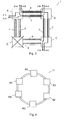
- Fig. 4 shows the network 11, which here has six nodes called K1, K2, K3, K4, K5 and K6. Like in the figures 1-3, the nodes are connected by two fibres here too, there being used one fibre for each transmission direction, each fibre accommodating working channels as well as protection channels. Since the established connections are bi-directional, as described above, we will, however, below just consider the two fibres as a transmission line having a plurality of time slots.
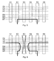
- Fig. 5 in which the ring is shown in the open state for reasons of illustration so that the points on the left-hand side of K1 are connected to the right-hand side of K6, shows four working and four protection channels or time slots.
- the working channels are called W1-W4, while the protection channels are correspondingly called P1-P4.
- the eight channels or time slots thus correspond e.g. to an STM-8 frame.
- the figure shows the network in normal operation, and it appears that a connection is set up between the nodes K2 and K5 via the channel W1
- Fig. 6 illustrates a situation in which drop-out of the node K3 occurs (or a double fibre rupture around this node occurs) so that the transmission between the nodes K2 and K5 can no longer take place as shown in fig. 1.
- the traffic in the interrupted connection is therefore coupled into the protection channel P1 in the adjacent nodes, i.e. K2 and K4, in a direction away from the error in the same manner as described above in relation to fig. 3.
- an arbitrary one of the four protection channels might be used; but the simplest control is obtained when e.g. P1 is used in connection with an interrupted connection in W1. As will be seen, the established connection may thus be re-created without problems in this situation.
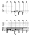
- Fig. 7 shows an example where a connection is first established between the nodes K3 and K4, it being then desired to establish a connection between K2 and K5.
- a control system introduces traffic into the ring, i.e. sets up connections, it will often try to place a channel on the lowermost time slots in a given fibre.
- the first connection K3-K4 is therefore placed in the time slot W1.
- the connection K2-K5 in e.g.
- the control system will therefore typically place the new connection as shown in the figure so that W1 is used from K2 to K3 and from K4 to K5, while W2 is used from K3 to K4 where W1 is occupied.
- time slot interchange or channel change takes place in the nodes K3 and K4.
- Fig. 8 shows another example where a number of connections have already been set up, as shown in thin line.
- the existing connections would prevent this if time slot interchange was not possible.
- the connection may be placed as shown in thick line in the figure, using the time slot W1 and the time slot W2, respectively.
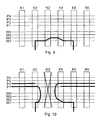
- Figures 9 and 10 show how the use of time slot interchange may be a problem when in case of certain error types it is attempted to re-create the traffic by means of the protection channels.
- the connection in fig. 9 corresponds to the one shown in fig. 7 and thus uses the time slot W1 from K2 to K3 and from K4 to K5, while W2 is used from K3 to K4.
- time slot interchange or channel change takes place in the nodes K3 and K4.
- Fig. 10 shows what happens when the node K3 is interrupted. In the node K2, the interrupted connection is coupled from W1 to the protection channel P1 as W1 was used between K2 and K3. In the node K4, the interrupted connection is correspondingly coupled from W2 to the protection channel P2, as W2 was used between K4 and K3.
- both of the two protection channels will have one end unconnected, i.e. the connection cannot be re-established, as is also shown in fig. 10. This means that in this situation the protection ring does not have the intended effect, and the traffic will be lost.
- Figs. 11 and 12 show how this may be solved according to the invention.
- Fig. 11 shows that a connection quite like the connection shown in fig. 9 is set up. It moreover appears from the top of the figure that each node has a "map" showing how its left adjacent node has connected each of the channels W1-W4 on the right-hand side with the corresponding channels (time slots) on the left-hand side. For example, W1 on the left-hand side of K3 is connected to W2 on the right-hand side of K3, and this is therefore reflected in the map which is registered in the node K4.
- the interrupted connection will be connected in the node K2 from W1 to P1, as described before, because no time slot interchange occurred in this node.
- the interrupted connection on the left side from W2, which was used between K4 and K3 is now connected to the protection channel P1, as it appears from the map registered in K4 that W2 on the right-hand side of K3 was connected to W1 on the left-hand side of K3.
- K4 knows that K3 switches from W2 to W1
- each node knows how the connections are set-up in the left adjacent node.
- the adjacent node on the right-hand side thereof will thus be able to compensate for the channel changes or time slot interchanges which occurred before the rupture in the interrupted node, and the connections can thus also be re-established in these situations.
- right and left may be interchanged, of course, so that each node knows how the connections are set-up in the right adjacent node, as the network is constructed symmetrically.
- K2 will connect W1 to P1
- the map of K5 merely indicates that W2 is coupled straight through in K4
- K5 will connect W2 to P2, and it is thus not possible to establish any auxiliary connection since P1 and P2 are no longer connected to each other.
- this solution can re-establish the connection when a single rupture of a transmission line between two nodes has taken place.
- the traffic can be saved, with the exception of the traffic to the dropped-out node itself, also even if channel change takes place, and no matter whether each connection uses the same channel at both ends of the connection.
- segmentation however, the traffic cannot be saved in all cases.
- Figs. 17 and 18 show an alternative embodiment of the invention which is also capable of ensuring that the connections are maintained in the situations where segmentation of the network takes place.
- each node here has a map which shows how the working channels have been set-up in each of the nodes of the network. The map shown is the one registered in K5; but, as is illustrated, a quite similar map is present in the other nodes.
- K2 will connect W1 to P1
- K5 since K5 now knows about the set-up in both K3 and K4 (as well as all other nodes), it is known that W2 on the right-hand side of K4 was connected to W1 on the left-hand side of K3 before the rupture.
- K5 can therefore directly connect W2 to P1, whereby the auxiliary connection via P1 is established. Connections which had been set up to the dropped-out nodes will be lost of course like in all other situations; but, on the other hand, K3 and K4 can still communicate with each other if just segmentation is involved.
- the map is instead registered in a control or monitoring system which is associated with the network, and it may then be the control or monitoring system that provides for the setting-up of the auxiliary connection, as described; but, of course, this requires that the remaining part of the network where the auxiliary connection is to be set up, is not isolated by the rupture from the control or monitoring system.
- this solution is capable of re-establishing the connection when a single rupture of a transmission line between two nodes has taken place.
- the traffic can be saved, with the exception of the traffic to the dropped-out node itself, also even if channel change takes place, and no matter whether each connection uses the same channel at both ends of the connection.
- the traffic can also be saved as just described in case of segmentation.
- the solution described last is therefore the one that allows for most situations; but, on the other hand, it is of course more complex in its structure, since, as described, each individual node is to know about the set-up in each of the others. In addition to storage space in the nodes, transmission capacity has to be used for transferring the set-up information to the individual nodes.
- the embodiment described first will therefore be preferred in many cases, it being then merely accepted that the traffic cannot be saved in any event in case of segmentation. Compromise solutions are also conceivable. If, e.g., each node has a map of how the two closest nodes are set-up., the traffic may be re-created also in the situations where two adjacent nodes drop out, corresponding to figs. 16 and 12; but not if three or more nodes drop out.
- the invention is not restricted to it, but may also be embodied in other ways within the scope of the subject-matter defined in the following claims.
- rings instead of the described MS SPRing having two fibres, other types of rings may be used, such as e.g. an MS SPRing having four fibres, or the ring may be adapted such that protection channels are just provided for some of the active working channels.
- the individual channels may be transmitted at independent wavelengths in a wavelength-division multiplex system instead of in a time-division multiplex system, or they may be transferred on their respective parallel cables.
- the protection channels may be utilized for the transmission of low priority traffic, without this being of any importance for the mode of operation of the invention.
Landscapes
- Engineering & Computer Science (AREA)
- Computer Networks & Wireless Communication (AREA)
- Signal Processing (AREA)
- Small-Scale Networks (AREA)
Priority Applications (1)
| Application Number | Priority Date | Filing Date | Title |
|---|---|---|---|
| DK98929240T DK1005740T3 (da) | 1997-06-27 | 1998-06-26 | Fremgangsmåde til transmission af data i et ringformet teletransmissionsnetværk samt et sådant netværk og netværkselement dertil |
Applications Claiming Priority (3)
| Application Number | Priority Date | Filing Date | Title |
|---|---|---|---|
| DK76897 | 1997-06-27 | ||
| DK76897 | 1997-06-27 | ||
| PCT/DK1998/000282 WO1999000943A2 (en) | 1997-06-27 | 1998-06-26 | A method of transmitting data in a ring-shaped teletransmission network, such as a network and a network element therefor |
Publications (2)
| Publication Number | Publication Date |
|---|---|
| EP1005740A2 EP1005740A2 (en) | 2000-06-07 |
| EP1005740B1 true EP1005740B1 (en) | 2006-02-22 |
Family
ID=8097336
Family Applications (1)
| Application Number | Title | Priority Date | Filing Date |
|---|---|---|---|
| EP98929240A Expired - Lifetime EP1005740B1 (en) | 1997-06-27 | 1998-06-26 | A method of transmitting data in a ring-shaped teletransmission network, such as a network and a network element therefor |
Country Status (5)
| Country | Link |
|---|---|
| EP (1) | EP1005740B1 (da) |
| AU (1) | AU7907998A (da) |
| DE (1) | DE69833548T2 (da) |
| DK (1) | DK1005740T3 (da) |
| WO (1) | WO1999000943A2 (da) |
Families Citing this family (2)
| Publication number | Priority date | Publication date | Assignee | Title |
|---|---|---|---|---|
| US6981228B1 (en) * | 2000-09-29 | 2005-12-27 | Sbc Technology Resources, Inc. | Interactive topology graphs for visualization and characterization of SONET consumption patterns |
| SE517816C2 (sv) * | 2000-10-27 | 2002-07-16 | Terraplay Systems Ab | Metod och anordning för en applikation |
Family Cites Families (3)
| Publication number | Priority date | Publication date | Assignee | Title |
|---|---|---|---|---|
| US5159595A (en) * | 1988-04-08 | 1992-10-27 | Northern Telecom Limited | Ring transmission system |
| JP2578704B2 (ja) * | 1991-03-26 | 1997-02-05 | 日本電信電話株式会社 | リング伝送網のループバック方法およびリング伝送装置 |
| US5179548A (en) * | 1991-06-27 | 1993-01-12 | Bell Communications Research, Inc. | Self-healing bidirectional logical-ring network using crossconnects |
-
1998
- 1998-06-26 AU AU79079/98A patent/AU7907998A/en not_active Abandoned
- 1998-06-26 DE DE69833548T patent/DE69833548T2/de not_active Expired - Fee Related
- 1998-06-26 WO PCT/DK1998/000282 patent/WO1999000943A2/en not_active Ceased
- 1998-06-26 EP EP98929240A patent/EP1005740B1/en not_active Expired - Lifetime
- 1998-06-26 DK DK98929240T patent/DK1005740T3/da active
Also Published As
| Publication number | Publication date |
|---|---|
| DE69833548T2 (de) | 2006-12-14 |
| AU7907998A (en) | 1999-01-19 |
| DE69833548D1 (de) | 2006-04-27 |
| DK1005740T3 (da) | 2006-06-26 |
| WO1999000943A2 (en) | 1999-01-07 |
| EP1005740A2 (en) | 2000-06-07 |
| WO1999000943A3 (en) | 1999-03-18 |
Similar Documents
| Publication | Publication Date | Title |
|---|---|---|
| EP1031198B1 (en) | Telecommunications network having shared protect capacity architecture | |
| CN100446445C (zh) | 光通信的保护装置和方法 | |
| CA2273053C (en) | Inter-ring cross-connect for survivable multi-wavelength optical communication networks | |
| US5159595A (en) | Ring transmission system | |
| US7319662B2 (en) | Virtual line switched ring | |
| US6400859B1 (en) | Optical ring protection having matched nodes and alternate secondary path | |
| US6579018B1 (en) | Four-fiber ring optical cross connect system using 4×4 switch matrices | |
| CA2395303A1 (en) | Two-fiber interconnected ring architecture | |
| US20090092044A1 (en) | Selector in switching matrix, line redundant method, and line redundant system | |
| EP1162859B1 (en) | Efficient architectures for protection against network failures | |
| US6404734B1 (en) | Scalable network restoration device | |
| EP1028550B1 (en) | Optical switch | |
| EP1014613A2 (en) | Shared optical protection in an optical communications network | |
| EP1005740B1 (en) | A method of transmitting data in a ring-shaped teletransmission network, such as a network and a network element therefor | |
| EP0878977B1 (en) | Improvements in an SDH-network provided with a shared protection system | |
| EP1113611B1 (en) | Method and apparatus for passing control information in a bidirectional line switched ring configuration | |
| US6744760B1 (en) | Node configurations within communication systems | |
| US6625653B1 (en) | Network protection architecture | |
| WO1999000942A2 (en) | A method of transmitting data in a ring-shaped teletransmission network, such a network and a network element therefor | |
| EP0600687B1 (en) | Dual connection method and apparatus in SDH ring network for data protection | |
| WO2000031927A1 (en) | Method for establishing alternative routes in a telecommunication network | |
| EP1133853A1 (en) | Method for establishing alternative routes in a telecommunication network |
Legal Events
| Date | Code | Title | Description |
|---|---|---|---|
| PUAI | Public reference made under article 153(3) epc to a published international application that has entered the european phase |
Free format text: ORIGINAL CODE: 0009012 |
|
| 17P | Request for examination filed |
Effective date: 19991228 |
|
| AK | Designated contracting states |
Kind code of ref document: A2 Designated state(s): DE DK FI FR GB IT SE |
|
| GRAP | Despatch of communication of intention to grant a patent |
Free format text: ORIGINAL CODE: EPIDOSNIGR1 |
|
| GRAS | Grant fee paid |
Free format text: ORIGINAL CODE: EPIDOSNIGR3 |
|
| GRAA | (expected) grant |
Free format text: ORIGINAL CODE: 0009210 |
|
| AK | Designated contracting states |
Kind code of ref document: B1 Designated state(s): DE DK FI FR GB IT SE |
|
| PG25 | Lapsed in a contracting state [announced via postgrant information from national office to epo] |
Ref country code: IT Free format text: LAPSE BECAUSE OF FAILURE TO SUBMIT A TRANSLATION OF THE DESCRIPTION OR TO PAY THE FEE WITHIN THE PRESCRIBED TIME-LIMIT;WARNING: LAPSES OF ITALIAN PATENTS WITH EFFECTIVE DATE BEFORE 2007 MAY HAVE OCCURRED AT ANY TIME BEFORE 2007. THE CORRECT EFFECTIVE DATE MAY BE DIFFERENT FROM THE ONE RECORDED. Effective date: 20060222 Ref country code: FI Free format text: LAPSE BECAUSE OF FAILURE TO SUBMIT A TRANSLATION OF THE DESCRIPTION OR TO PAY THE FEE WITHIN THE PRESCRIBED TIME-LIMIT Effective date: 20060222 |
|
| REG | Reference to a national code |
Ref country code: GB Ref legal event code: FG4D |
|
| REF | Corresponds to: |
Ref document number: 69833548 Country of ref document: DE Date of ref document: 20060427 Kind code of ref document: P |
|
| REG | Reference to a national code |
Ref country code: SE Ref legal event code: TRGR |
|
| REG | Reference to a national code |
Ref country code: DK Ref legal event code: T3 |
|
| ET | Fr: translation filed | ||
| PLBE | No opposition filed within time limit |
Free format text: ORIGINAL CODE: 0009261 |
|
| STAA | Information on the status of an ep patent application or granted ep patent |
Free format text: STATUS: NO OPPOSITION FILED WITHIN TIME LIMIT |
|
| 26N | No opposition filed |
Effective date: 20061123 |
|
| PGFP | Annual fee paid to national office [announced via postgrant information from national office to epo] |
Ref country code: SE Payment date: 20070607 Year of fee payment: 10 |
|
| EUG | Se: european patent has lapsed | ||
| PGFP | Annual fee paid to national office [announced via postgrant information from national office to epo] |
Ref country code: DK Payment date: 20090615 Year of fee payment: 12 |
|
| PGFP | Annual fee paid to national office [announced via postgrant information from national office to epo] |
Ref country code: GB Payment date: 20090624 Year of fee payment: 12 Ref country code: DE Payment date: 20090619 Year of fee payment: 12 |
|
| PG25 | Lapsed in a contracting state [announced via postgrant information from national office to epo] |
Ref country code: SE Free format text: LAPSE BECAUSE OF NON-PAYMENT OF DUE FEES Effective date: 20080627 |
|
| REG | Reference to a national code |
Ref country code: DK Ref legal event code: EBP |
|
| GBPC | Gb: european patent ceased through non-payment of renewal fee |
Effective date: 20100626 |
|
| REG | Reference to a national code |
Ref country code: FR Ref legal event code: ST Effective date: 20110228 |
|
| PG25 | Lapsed in a contracting state [announced via postgrant information from national office to epo] |
Ref country code: DE Free format text: LAPSE BECAUSE OF NON-PAYMENT OF DUE FEES Effective date: 20110101 |
|
| PG25 | Lapsed in a contracting state [announced via postgrant information from national office to epo] |
Ref country code: FR Free format text: LAPSE BECAUSE OF NON-PAYMENT OF DUE FEES Effective date: 20100630 |
|
| PG25 | Lapsed in a contracting state [announced via postgrant information from national office to epo] |
Ref country code: GB Free format text: LAPSE BECAUSE OF NON-PAYMENT OF DUE FEES Effective date: 20100626 |
|
| PG25 | Lapsed in a contracting state [announced via postgrant information from national office to epo] |
Ref country code: DK Free format text: LAPSE BECAUSE OF NON-PAYMENT OF DUE FEES Effective date: 20100630 |
|
| PGFP | Annual fee paid to national office [announced via postgrant information from national office to epo] |
Ref country code: FR Payment date: 20090611 Year of fee payment: 12 |