EP1005767B1 - Transmission de donnees a grande vitesse dans un systeme de communication mobile - Google Patents
Transmission de donnees a grande vitesse dans un systeme de communication mobile Download PDFInfo
- Publication number
- EP1005767B1 EP1005767B1 EP99923621A EP99923621A EP1005767B1 EP 1005767 B1 EP1005767 B1 EP 1005767B1 EP 99923621 A EP99923621 A EP 99923621A EP 99923621 A EP99923621 A EP 99923621A EP 1005767 B1 EP1005767 B1 EP 1005767B1
- Authority
- EP
- European Patent Office
- Prior art keywords
- frames
- data
- transmission
- frame
- base station
- Prior art date
- Legal status (The legal status is an assumption and is not a legal conclusion. Google has not performed a legal analysis and makes no representation as to the accuracy of the status listed.)
- Expired - Lifetime
Links
- 230000005540 biological transmission Effects 0.000 title claims abstract description 142
- 238000010295 mobile communication Methods 0.000 title claims abstract description 22
- 238000000034 method Methods 0.000 claims description 24
- 239000000284 extract Substances 0.000 abstract description 6
- 230000006978 adaptation Effects 0.000 description 18
- 210000004271 bone marrow stromal cell Anatomy 0.000 description 14
- 238000004891 communication Methods 0.000 description 5
- 238000005516 engineering process Methods 0.000 description 4
- 230000008569 process Effects 0.000 description 3
- 230000001413 cellular effect Effects 0.000 description 2
- 238000006243 chemical reaction Methods 0.000 description 2
- 230000001934 delay Effects 0.000 description 2
- 230000011664 signaling Effects 0.000 description 2
- 230000007480 spreading Effects 0.000 description 2
- 230000001360 synchronised effect Effects 0.000 description 2
- 230000008901 benefit Effects 0.000 description 1
- 210000004027 cell Anatomy 0.000 description 1
- 230000008859 change Effects 0.000 description 1
- 230000001419 dependent effect Effects 0.000 description 1
- 238000012423 maintenance Methods 0.000 description 1
- 230000000306 recurrent effect Effects 0.000 description 1
- 230000035945 sensitivity Effects 0.000 description 1
Images


Classifications
-
- H—ELECTRICITY
- H04—ELECTRIC COMMUNICATION TECHNIQUE
- H04W—WIRELESS COMMUNICATION NETWORKS
- H04W92/00—Interfaces specially adapted for wireless communication networks
- H04W92/04—Interfaces between hierarchically different network devices
- H04W92/045—Interfaces between hierarchically different network devices between access point and backbone network device
-
- H—ELECTRICITY
- H04—ELECTRIC COMMUNICATION TECHNIQUE
- H04W—WIRELESS COMMUNICATION NETWORKS
- H04W88/00—Devices specially adapted for wireless communication networks, e.g. terminals, base stations or access point devices
- H04W88/18—Service support devices; Network management devices
- H04W88/181—Transcoding devices; Rate adaptation devices
Definitions
- the invention relates to high-speed data transmission in mobile communications systems, especially when a multichannel configuration is used.
- TDMA time division multiple access
- CDMA code division multiple access
- FDMA frequency division multiple access
- TDMA time division multiple access
- communication over a radio path takes place on a time division basis in successive recurrent TDMA frames, each of which comprises several time slots.
- a short information packet is transmitted in each time slot in the form of a radio-frequency burst of a limited duration, consisting of a number of modulated bits.
- the time slots are mainly used for conveying control channels and traffic channels. Traffic channels are used for transmitting speech and data, whereas control channels are used for signalling between a base station and mobile stations.
- GSM Global System for Mobile Communications
- a traffic channel is determined by a unique spreading code assigned to a mobile station, whereas in an FDMA system a traffic channel is determined by a radio channel.
- Maximum data transfer rate on a single traffic channel is limited to a rather low level according to the available bandwidth and the channel coding and error coding used in the transmission.
- the user data rate of a traffic channel employing one time slot was limited to 9.6 kbit/s according to the original specifications, and the radio interface rate was 12 kbit/s.
- this has been found insufficient for many of the new teleservices, such as telefax, video transmission etc., wherefore new mobile systems are being provided with high-speed data transmission services based on so-called multichannel technology (see e.g. WO 96/18248).
- multichannel technology a mobile station is provided with a higher bit rate and a greater bandwidth by means of several parallel basic traffic channels (e.g.
- high-speed data service HSCSD High Speed Circuit Switched Data
- GSM 01.34, GSM 02.34 and GSM 03.34 of the ETSI European Telecommunications Standards Institute
- a high-speed data signal is divided into separate data streams, which are then transferred via N subchannels (N traffic channel time slots) at the radio interface and, correspondingly, via N subchannels between the base station and the mobile services switching centre (transcoder). After the data streams have been divided, they are transferred on the subchannels as if they were mutually independent until they are combined at the receiving end.
- the GSM HSCSD is capable of supporting a radio interface rate of 96 kbit/s (8 ⁇ 12 kbit/s) and user rates of up to 64 kbit/s and 76.8 kbit/s (8 ⁇ 9.6 kbit/s) at the radio interface.
- the EDGE (Enhanced Data Rates for GSM Evolution) project of the ETSI is in the process of developing a new modulation method providing a higher data rate per time slot than the present GMSK modulation, while retaining the channel spacing of 200 kHz and the TDMA frame structure. This enables supporting the present HSCSD data services with a lower number of time slots.
- the new modulation method also makes it possible to provide new data services with a data rate that may be as high as 64 kbit/s per time slot or over 64 kbit/s (n * 64 kbit/s) in a multislot constellation.
- the radio interface rate is either 28.8 kbit/s or 38.4 kbit/s on a single channel.
- a problem related to multichannel technology is how to distribute the data arriving from high-speed data sources into separate channels (subchannels) and how to assemble the data received from the separate channels into the correct (original) order. This problem relates to both the mobile station and the mobile communication network.
- the frame numbering is also transferred in each frame.
- the arrangement disclosed above is described for example in ETSI/GSM recommendation 03.34 and in Finnish Patent 97187.
- Such inband channel and frame numbering consumes the channel capacity, which has been reduced by inserting the channel and frame numbering in place of the data in V.110 frames.
- the data rate at the radio interface and the data rate over a leg between a base station and an interworking function (usually located remote from the base station at a mobile services switching centre) are no longer directly compatible or adapted one-to-one, unless entirely new rate adaptation functions are defined between the base station and the interworking function.
- the EDGE project suggests several new alternative solutions for this problem.
- One alternative is to define completely new rate adaptation functions, optimized for the EDGE, between the base station and the interworking function.
- Another alternative manner is to use existing TRAU formats and physical 16 kbit/s channel structures at an Abis interface. Since data rates exceeding 14.4 kbit/s cannot be rate-adapted into one 14.4 kbit/s TRAU frame, TRAU frames of several Abis transmission channels must be used to provide the higher capacity required by the EDGE radio interface. In this case, the base station must process a higher number of Abis transmission channels than the number of time slots used at the EDGE radio interface.
- one time slot (channel) at the EDGE radio interface would require two Abis transmission channels with a 14.4 kbit/s TRAU format.
- two 28.8 kbit/s EDGE channels (57.6 kbit/s multichannel configuration) would require four Abis transmission channels.
- An advantage of using the present rate adaptation functions is that the EDGE radio interface does not require changes in the Abis interface and the TRAUs.
- a drawback is the increased complexity of the base station, which results from the base station having to process two different legs with different frames and channel numbers.
- the base station In the uplink direction the base station must receive the EDGE frames from the radio interface channels, restore the order of data, place the data in the TRAU frames and transmit the frames via a greater number of transmission channels to the interworking function.
- the base station in the downlink direction the base station must receive the TRAU frames from the transmission channels, restore the order of data, place the data in the EDGE frames and transmit the frames via a smaller number of channels at the radio interface.
- An object of the present invention is to simplify the operation and structure of a base station in a mobile communications system which requires a higher number of transmission channels than traffic channels, and where the traffic and transmission channels employ different frame structures.
- the invention rolates to a method according to claim 1, a digital mobile communications system according to claim 7, a base station according to claim 13 and a mobile station according to claim 16.
- Each high-speed traffic channel at the radio interface requires two or more lower-rate transmission channels between the base station and the interworking function, which is typically located at the mobile services switching centre.
- Radio frames such as EDGE frames, are transmitted over a radio interface traffic channel.
- Transmission channels are used for transmission of transmission frames, such as TRAU frames. Since each transparent call always has at least two parallel transmission channels via which the transmission frames are transmitted, the base station and the interworking function provide the transmission frames to be transmitted with frame and/or channel numbering which indicates the order of the transmitted frames and/or the transmission channel via which the transmission frame was transferred.
- the base station does not restore the order of the downlink transmission frames according to the aforementioned frame and/or channel numbering, but it places the data of the transmission frames and at least the frame and/or channel numbering in the payload of the downlink radio frame to the transmitted. lnstead, the mobile station, which extracts the data and the frame and/or channel numbering of the transmission frames from the downlink radio frames, restores the correct order of the data on the basis of this numbering.
- the radio interface also employs two or more traffic channels, for example according to the GSM HSCSD concept. Even in such a case the radio interface does not require separate frame and/or channel numbering to restore the order of the data if the internal timing of the radio system, comprising time slot numbering, is used for this purpose. In other words, it is possible to utilize the natural order of the time slots in the TDM system (e.g. time slot 0 precedes times slot 1, time slot 1 precedes time slot 2, ..., time slot 6 precedes time slot 7, time slot 7 precedes time slot 0 of the next burst/frame, etc.). If separate numbering is used at the radio interface, the base station can provide the downlink radio frames to be transmitted with some other frame and/or channel numbering.
- the mobile station restores the order of the received radio frames or the contents thereof on the basis of this other numbering before the data and the frame and/or channel numbering of the transmission frames are separated from the radio frames.
- the mobile station thereafter restores the order of the data on the basis of the frame and/or channel numbering of the transmission frames.
- the mobile station provides the uplink radio frames to be transmitted with the aforementioned other frame and/or channel numbering.
- the base station does not restore the order of the radio frames on the basis of the other numbering, but it places the data and the frame and/or channel numbering of the radio frames in the uplink transmission frames to be transmitted.
- the base station also provides the uplink transmission frames to be transmitted with its own frame and/or channel numbering.
- the interworking function restores the order of the transmission frames or the contents thereof on the basis of this numbering before the data and the frame and/or channel numbering of the radio frames are separated from the transmission frames.
- the interworking function thereafter restores the order of the data on the basis of the frame and/or channel numbering of the radio frames.
- the base station can also insert other control and status information of the transmission frames into the downlink radio frames.
- the base station preferably inserts the transmission frames into the radio frames as such, so that the base station does not have to identify the frame and channel information at all.
- the base station can also place in the uplink transmission frames other control information for the radio frames, preferably the radio frames as such.
- an objective of the invention is to develop a method and an apparatus implementing the method such that the aforementioned problems can be solved.
- the objectives of the invention are achieved with a method and a system which are characterized by what is disclosed in the independent claims.
- the preferred embodiments of the invention are disclosed in the dependent claims.
- the present invention can be applied in all digital wireless telecommunication systems, such as cellular systems, WLL-type (Wireless Local Loop) and RLL-type (Radio Local Loop) networks and satellite-based mobile communications systems, among others, to introduce a new high-speed traffic channel at the radio interface without a need to define new rate adaptations for the transmission connections.
- the term 'mobile communications system' refers generally to all wireless telecommunication systems.
- the physical concept of a traffic channel varies in different multiple access methods, and it is primarily defined by means of a time slot in TDMA systems, a spreading code in CDMA systems, a radio channel in FDMA systems, a combination of the former, etc.
- the basic idea of the present invention is independent of the type of the traffic channel and the multiple access method used.
- the primarily field of application of the invention is the introduction of an EDGE radio interface into a GSM system or a corresponding change in other GSM-based systems, such as DCS1800 (Digital Communication System) and the US digital cellular system PCS (Personal Communication System), and in WLL systems based on the aforementioned systems.
- DCS1800 Digital Communication System
- PCS Personal Digital cellular system
- WLL Wireless Local Area Network
- the invention will be described below by using as an example the GSM mobile system.
- the structure and operation of the GSM system are well known to those skilled in the art and they are defined in the GSM specifications of the ETSI (European Telecommunications Standards Institute). Reference is also made to The GSM System for Mobile Communications, M. Mouly & M. Pautet, Palaiseau, France, 1992, ISBN:2-9507190-0-7.
- the basic structure of the GSM system comprises two parts: a base station system BSS and a network subsystem NSS.
- the BSS and mobile stations MS communicate via radio connections.
- each cell is served by a base station BTS.
- a number of base stations are connected to a base station controller BSC, which controls the radio frequencies and channels used by the BTS.
- the BSCs are connected to a mobile services switching centre MSC.
- Certain MSCs are connected to other telecommunication networks, such as the public switched telephone network PSTN, and they comprise gateway functions for calls bound for and arriving from these networks. These MSCs are known as gateway MSCs (GMSC).
- GMSC gateway MSCs
- a mobile system comprises adapter functions for adapting an intranetwork data link to protocols used by terminal equipments and other telecommunication networks.
- the adapter functions typically include a terminal adaptation function TAF placed at the interface between a mobile station and a data terminal equipment connected thereto, and an interworking function IWF situated at the interface between the mobile network and another telecommunication network, usually in connection with an MSC.
- An MSC typically comprises several different types of adapter equipment pools for supporting different data services and protocols, such as a modem pool with modems and facsimile adapters for modem and facsimile services, a UDI/RDI rate adapter pool, etc.
- a data link is set up between a TAF of the MS and an IWF in the mobile network.
- the TAF adapts a data terminal equipment DTE connected to the MS to the aforementioned GSM data link that is set up over a physical connection using one or several traffic channels.
- the IWF connects the GSM data link to another network, such as an ISDN, another GSM network or a PSTN.
- the bearer services in the GSM system are defined in the GSM specification 02.02 and the teleservices are defined in the GSM specification 02.03.
- the bearer services are usually divided into groups according to a property, for example asynchronous and synchronous bearer services. Each of these groups comprises a number of bearer services, such as a transparent service (T) and a non-transparent service (NT).
- T transparent service
- NT non-transparent service
- T transparent service
- NT non-transparent service
- a transparent service the data to be transmitted is unstructured and transmission errors are only corrected by means of channel coding.
- NT non-transparent service
- the data to be transmitted is structured into protocol data units (PDU), and transmission errors are corrected by using (in addition to channel coding) automatic retransmission protocols.
- PDU protocol data units
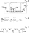
- FIG. 1 shows an example of protocols and functions required in an IWF (either in an MSC or a WLL-specific network element) for transparent bearer services.
- a transparent circuit switched connection between a TAF and an IWF on a GSM traffic channel comprises several protocol layers that are common to all these services. They include different rate adaptation RA functions, such as RA1' between the TAF and a channel codec unit CCU located in the BSS, RA1 between the CCU and the IWF, RAA between the CCU and a transcoder unit TRAU located remote from the base station, and RA2 between the TRAU and the IWF.
- the rate adaptation functions RA are defined in the GSM recommendations 04.21 and 08.20.
- Communication between the CCU and the TRAU is defined in the GSM recommendation 08.60.
- Information that has been RA1' rate-adapted at the radio interface is also channel-coded as defined in the GSM recommendation 5.03, which is illustrated by blocks FEC in the MS and the CCU.
- the IWF and the TAF also comprise higher-level protocols that are specific to each service.
- the IWF requires asynchronous-to-synchronous conversion RA0 and a modem or a rate adapter towards the fixed network.
- a transparent signal propagates through the traffic channel between the terminal interface and the PSTN/ISDN.
- a transparent synchronous configuration is otherwise identical but it has no rate adaptation RA0.
- Figure 1 relates to a network configuration where the transcoder and some of the rate adaptations are situated outside the BTS in a so-called remote transcoder TRAU.
- the transcoder is operationally a part of the BSC. Physically the TRAU may be located either in the BSC or the MSC.
- the interface between the TRAU and the BTS is called an Abis interface.
- the Abis interface comprises 16 kbit/s traffic channels, four of which can be transmitted on a single standard 64 kbit/s channel.
- Information is transmitted between the CCU and the TRAU in fixed-length frames called TRAU frames. In these frames are transmitted both speech/data and control signals related to the TRAU.
- RA1/RAA is required in addition to the other rate adaptations.
- RA1'/RAA' converts the radio frames (blocks) into an E-TRAU format, and vice versa.
- the RAA' function converts the E-TRAU frame into an A-TRAU frame, and vice versa.
- a high-speed data signal is divided into separate data streams, which are then transmitted via N subchannels (N traffic channel time slots) at the radio interface and via N transmission channels (16 kbit/s) between the BTS and the IWF.
- N subchannels N traffic channel time slots
- N transmission channels (16 kbit/s) between the BTS and the IWF.
- the data streams are transferred in the subchannels as if they were mutually independent until they are combined in the IWF or the MS.
- these N subchannels are parts of the same HSCSD connection, in other words they form one HSCSD traffic channel.
- data streams are divided and combined in a modified RA0, which is thus common to all the subchannels.
- each subchannel comprises separately the same protocol stack RA1'-FEC-FEC-RA1'-RAA-RAA-RA2-RA2-RA1 or RA1'-FEC-FEC-RA1'-RAA'-RAA'-RA2-RA2-RA1, which is shown in Figures 1 and 2, respectively, for one traffic channel between the MS/TAF and the MSC/IWF.
- the traffic channels are numbered in order to maintain the order of the data.
- superframing is used within a traffic channel to increase the tolerance towards differences in transmission delays between the traffic channels.
- the channel and frame numbering is transmitted in the form of inband signalling.
- FIG. 3 illustrates a multichannel configuration according to the GSM recommendations for TCH/F14.4 channel coding.
- An HSCSD traffic channel of 28.8 kbit/s comprises two parallel 14.4 kbit/s channels between the MS and the MSC/IWF.
- each 28.8 EDGE channel requires two 14.4 kbit/s channels between the BTS and the MSC.
- each 38.4 EDGE channel requires three 14.4 channels between the BTS and the MSC. Therefore the number of transmission channels is higher than the number of radio interface traffic channels, which differs from a conventional GSM channel configuration.
- a BTS must be implemented with a more complicated structure than previously in order that it is capable of performing the required conversions and adaptations between the radio interface and the Abis interface. Another requirement is the maintenance of the order of data when the data is transmitted via several parallel transmission channels. This requirement is particularly challenging when the radio interface also has a multichannel configuration.
- the aim of the invention is to simplify the implementation of a base station in channel configurations of the type shown in Figure 4. Since each transparent call always has at least two parallel TCH/F14.4 transmission channels via which the TRAU frames are transmitted, the BTS and the IWF provide the transmission frames to be transmitted with frame and/or channel numbering which indicates the order of the transmitted frames and/or the transmission channel via which the TRAU frame was transmitted. However, according to the invention the BTS does not restore the order of the downlink E-TRAU frames according to the aforementioned frame and/or channel numbering, but it places the data of the E-TRAU frames and at least the frame and/or channel numbering in the payload of the downlink EDGE radio interface frame to be transmitted.
- the MS which extracts the data and the frame and/or channel numbering of the TRAU frames from the downlink EDGE frames, restores the correct order of the data on the basis of this numbering.
- the same procedure is followed in each case regardless of whether the radio interface has a single-channel or multichannel configuration.
- the MS and the IWF restore the order of the data, which simplifies the structure of the BTS, whereas the MS and the IWF become more complex.
- the order of the data can be restored at the radio interface alternatively by means of the internal timing of the radio system, comprising time slot numbering. In such a case there is no need to provide the radio frames with numbering for this purpose.
- radio interface also has a multichannel configuration. It is assumed that a transparent call has a channel configuration as shown in Figure 4b, i.e. two EDGE traffic channels (2*28.8 kbit/s) at the radio interface and four GSM TCH/F14.4 channels between the BTS and the IWF.
- the MSC/IWF divides a high-speed 57.6/64 kbit/s data stream into A-TRAU frames of four TCH14.4 channels and provides the A-TRAU frames with frame and channel numbering according to the GSM recommendations.
- the RAA' function of the transcoder TRAU (which, in practice, can be a part of the IWF) converts the A-TRAU frames into E-TRAU frames on each subchannel according to the GSM recommendations.
- the BTS receives the downlink E-TRAU frames and places the entire contents thereof, i.e. the data, status/control information and TRAU frame and/or channel numbering, in the EDGE frames, as shown in Figure 5.
- one EDGE frame is capable of carrying the payload of two E-TRAU frames in its payload.
- the BTS does not try to check or restore the order of the E-TRAU frames.
- the BTS also provides the EDGE frames to be transmitted to the different EDGE traffic channels with EDGE frame and channel numbering.
- the MS receives the downlink EDGE frames and extracts the payload (the contents of the E-TRAU frames), simultaneously restoring the order of the data on the basis of the EDGE frame and channel numbering.
- the MS thereafter separates the data and the control information of the E-TRAU frames from each other and restores the order of the data on the basis of the TRAU frame and/or channel numbering.
- the result is the original high-speed 57.6/64 kbit/s data stream.
- the MS/TAF divides the high-speed 57.6/64 kbit/s data stream into the uplink EDGE frames of two 28.8 kbit/s EDGE traffic channels and provides the EDGE frames with EDGE frame and channel numbering.
- the BTS receives the uplink EDGE frames but it does not check or restore their order on the basis of the EDGE numbering. Instead, the BTS inserts the uplink EDGE frames as such into the data field of the E-TRAU frames, as shown in Figure 6. In this case two E-TRAU frames are needed for each EDGE frame. Unless the rate of the EDGE channel is a multiple of the transmission channel rate, some kind of rate adaptation is required.
- the BTS divides the E-TRAU frames into four TCH/F14.4 channels and provides the frames with TRAU frame and channel numbering similarly as the IWF does in the downlink direction.
- the RAA' function of the TRAU converts the E-TRAU frames into A-TRAU frames on each subchannel according to the GSM recommendations.
- the IWF receives the A-TRAU frames and extracts the payload (i.e. the EDGE radio frames) from the A-TRAU frames and restores the order of the payload on the basis of the TRAU frame and channel numbering.
- the IWF thereafter extracts the data and the control information from the EDGE frames and restores the order of the data on the basis of the EDGE frame and/or channel numbering. The result is the original high-speed data stream.
Landscapes
- Engineering & Computer Science (AREA)
- Computer Networks & Wireless Communication (AREA)
- Signal Processing (AREA)
- Mobile Radio Communication Systems (AREA)
- Radio Relay Systems (AREA)
- Reduction Or Emphasis Of Bandwidth Of Signals (AREA)
Claims (18)
- Procédé de transmission de données dans un système de communication mobile numérique comprenant les étapes de :caractérisé en ce qu'il consiste àtransmission de données dans des trames radio via N canaux de trafic sur une interface radio entre une station de base (BTS) et une station mobile (MS),transmission de données dans des trames de transmission via M canaux de transmission entre la station de base (BTS) et une fonction d'interfonctionnement (IWF), où N et M sont des nombres entiers positifs et M≥2N,fourniture de trames de transmission transmises dans la station de base (BTS) et la fonction d'interfonctionnement (IWF) avec la numérotation des canaux et/ou de trames permettant la restauration de l'ordre original des données au niveau de l'extrémité de réception,placement, dans la station de base (BTS), des données des trames radio dans les trames de transmission dans la direction de liaison montante, etplacement, dans la station de base (BTS), des données des trames de transmission dans les trames radio dans la direction de liaison descendante,
placer, dans la station de base (BTS), au moins la numérotation des canaux et/ou des trames des trames de transmission en plus des données en tant que charge utile des trames radio, et
restaurer l'ordre des données dans la station mobile (MS) sur la base de ladite numérotation des canaux et/ou des trames des trames de transmission. - Procédé selon la revendication 1, caractérisé en ce qu'il consiste à
placer, dans la station de base (BTS), les informations sur le contrôle de la trame de transmission, de préférence le contenu intégral de la trame en tant que telle, en tant que charge utile des trames radio en plus des données dans la direction de liaison descendante. - Procédé selon la revendication 1 ou 2, caractérisé en ce qu'il consiste à
utiliser la synchronisation interne du système radio, comprenant la numérotation de la tranche de temps, pour restaurer l'ordre des données transmises via différents canaux de trafic sur l'interface radio. - Procédé de transmission de données selon la revendication 1, caractérisé en ce qu'il consiste à
transmettre des données dans des trames radio via N canaux de trafic sur une interface radio entre une station de base (BTS) et la station mobile (MS), où N≥2,
fournir les trames radio transmises avec la première numérotation des canaux et/ou des trames dans la station mobile (MS) et la station de base (BTS),
transmettre les données dans les trames de transmission via M canaux de transmission entre la station de base (BTS) et la fonction d'interfonctionnement (IWF), où M≥2N,
fournir les trames de transmission transmises avec la deuxième numérotation des canaux et/ou des trames dans la station de base (BTS) et la fonction d'interfonctionnement (IWF),
placer, dans la station de base (BTS), des données des trames radio dans les trames de transmission dans la direction de liaison montante, et
placer, dans la station de base (BTS), des données des trames de transmission dans les trames radio dans la direction de liaison descendante,
placer également, dans la station de base (BTS), la deuxième numérotation de canaux et/ou de trames des trames de transmission en plus des données en tant que charge utile des trames radio dans la direction de liaison descendante, et
restaurer l'ordre original des trames de données dans la station mobile (MS) au moyen de la première numérotation de canaux et/ou de trames des trames radio,
extraire des trames de données les données et la deuxième numérotation des canaux et/ou des trames des trames de transmission,
restaurer l'ordre des données dans la station mobile (MS) sur la base de ladite deuxième numérotation des canaux et/ou des trames des trames de transmission,
placer également, dans la station de base (BTS), la première numérotation de canaux et/ou de trames des trames radio en plus des données en tant que charge utile des trames de transmission dans la direction de liaison montante,
restaurer l'ordre original des trames de transmission dans la fonction d'interfonctionnement (IWF) au moyen de la deuxième numérotation de canaux et/ou de trames des trames de transmission,
extraire des trames de transmission les premières données et la numérotation des canaux et/ou des trames des trames radio,
restaurer l'ordre des données dans la fonction d'interfonctionnement (IWF) sur la base de ladite première numérotation des canaux et/ou des trames des trames radio. - Procédé selon la revendication 4, caractérisé en ce qu'il consiste à
placer dans les trames radio l'ensemble des informations sur le contrôle des trames de transmission, ou les trames de transmission en tant que telles, et/ou
placer dans les trames de transmission l'ensemble des informations sur le contrôle des trames radio, ou les trames radio en tant que telles. - Procédé selon l'une quelconque des revendications 1 à 5, caractérisé en ce que
entre la station de base (BTS) et la fonction d'interfonctionnement (IWF), il existe une unité de transcodeur à distance (TRAU), et en ce que le procédé comprend en outre les étapes consistant à
utiliser les trames de transmission d'un premier type entre la station de base (BTS) et le transcodeur à distance (TRAU),
utiliser les trames de transmission d'un deuxième type entre le transcodeur à distance (TRAU) et la fonction d'interfonctionnement (IWF),
convertir les trames de transmission du premier type en trames de transmission du deuxième type et vice-versa dans le transcodeur à distance (TRAU). - Système de communication mobile numérique où
une configuration de canal d'un appel de données transparent comprend N canaux de trafic au niveau de l'interface radio entre une station de base (BTS) et une station mobile (MS), et M canaux de transmission entre une station de base (BTS) et une fonction d'interfonctionnement (IWF), où N et M sont des nombres entiers positifs et M≥2N, les données étant transférées dans les trames de transmission sur les canaux de transmission et dans les trames radio sur les canaux de trafic de l'interface radio,
la station de base (BTS) et la fonction d'interfonctionnement (IWF) sont disposées de manière à proposer aux trames de transmission transmises une numérotation des canaux et/ou des trames dans la station de base (BTS) et dans la fonction d'interfonctionnement (IWF), la numérotation permettant la restauration de l'ordre original des données au niveau de l'extrémité réceptrice,
caractérisé en ce que
la station de base (BTS) étant disposée de manière à placer non seulement les données mais aussi au moins la numérotation des canaux et/ou des trames des trames de transmission en tant que charge utile des trames radio, et
la station mobile (MS) étant disposée de manière à restaurer l'ordre des données sur la base de ladite numérotation des canaux et/ou des trames des trames de transmission. - Système de communication mobile selon la revendication 7, caractérisé en ce que la station de base (BTS) est disposée de manière à placer le contenu intégral de la trame de transmission en tant que telle en tant que charge utile des trames radio.
- Système de communication mobile selon les revendications 7 ou 8, caractérisé en ce que l'ordre des données transmises sur l'interface radio via différents canaux de trafic est restauré au moyen de la synchronisation interne du système radio comprenant la numérotation de la tranche de temps.
- Système de communication mobile numérique selon la revendication 7, caractérisé en ce que
la configuration de canal de l'appel de données transparent comprend N canaux de trafic au niveau de l'interface radio entre la station de base (BTS) et la station mobile (MS), et M canaux de transmission entre la station de base (BTS) et la fonction d'interfonctionnement (IWF), où N≥2 et M≥2N, les données étant transférées dans des trames de transmission sur les canaux de transmission et dans des trames radio sur les canaux de trafic de l'interface radio.
la station de base (BTS) et la fonction d'interfonctionnement (IWF) sont disposées de manière à fournir les trames de transmission transmises avec la première numérotation des canaux et/ou des trames,
la station de base (BTS) et station mobile (MS) sont disposées de manière à fournir les trames radio transmises avec la deuxième numérotation des canaux et/ou des trames,
la station de base (BTS) est disposée de manière à placer non seulement les données mais aussi au moins la première numérotation des canaux et/ou des trames des trames de transmission en tant que charge utile des trames radio dans la direction de liaison descendante,
la station mobile (MS) est disposée de manière à restaurer l'ordre original des trames radio ou leur charge utile au moyen de ladite deuxième numérotation des canaux et/ou des trames,
la station mobile (MS) est disposée de manière à extraire les données et ladite première numérotation des canaux et/ou des trames à partir de la charge utile des trames radio,
la station mobile (MS) est disposée de manière à restaurer l'ordre des données sur la base de ladite première numérotation des canaux et/ou des trames,
la station de base (BTS) est disposée de manière à placer non seulement les données mais aussi la deuxième numérotation des canaux et/ou des trames des trames radio en tant que charge utile des trames de transmission dans la direction de liaison montante,
la fonction d'interfonctionnement (IWF) est disposée de manière à restaurer l'ordre original des trames de transmission ou leur charge utile dans la fonction d'interfonctionnement au moyen de ladite première numérotation des canaux et/ou des trames,
la fonction d'interfonctionnement (IWF) est disposée de manière à extraire les données et ladite deuxième numérotation des canaux et/ou des trames à partir de la charge utile des trames de transmission,
la fonction d'interfonctionnement (IWF) est disposée de manière à restaurer l'ordre des données sur la base de ladite deuxième numérotation des canaux et/ou des trames. - Système de communication mobile conformément à la revendication 10, caractérisé en ce que
la-station de base (BTS) est disposée de manière à placer dans les trames radio toutes les informations sur le contrôle des trames de transmission ou l'intégralité des contenus de la trame de transmission en tant que telle, et/ou
la station de base (BTS) est disposée de manière à placer dans les trames de transmission toutes les informations sur le contrôle des trames radio, ou les trames radio en tant que telles. - Système de communication mobile selon l'une quelconque des revendications 7 à 11, caractérisé en ce qu'une unité de transcodeur à distance (TRAU) se trouve entre la station de base (BTS) et la fonction d'interfonctionnement, et en ce que le système de communication mobile comprend des trames de transmission du premier type entre la station de base (BTS) et le transcodeur à distance, et les trames de transmission du deuxième type entre le transcodeur à distance et la fonction d'interfonctionnement, et en ce que le transcodeur à distance est disposé de manière à convertir les trames de transmission du premier type en trames de transmission du deuxième type, et vice versa.
- Station de base dans un système de communication mobile où une configuration de canal d'un appel de données transparent comprend N canaux de trafic au niveau de l'interface radio entre une station de base (BTS) et une station mobile (MS), et M canaux de transmission entre la station de base (BTS) et une fonction d'interfonctionnement (IWF), où N et M sont des nombres entiers positifs et où M≥2N, les données étant transférées dans des trames de transmission sur des canaux de transmission et dans des trames radio sur des canaux de trafic de l'interface radio, les trames de transmission comprenant la numérotation des canaux et/ou des trames permettant de restaurer l'ordre des données si l'ordre change à cause des différentes propriétés de transmission des canaux de transmission, caractérisée en ce que la station de base (BTS) est disposée de manière à placer, en plus des données, au moins la numérotation des canaux et/ou des trames des trames de transmission en tant que charge utile des trames radio pour la restauration de l'ordre des données dans la station mobile.
- Station de base selon la revendication 13, caractérisée en ce que N≥2 et en ce que l'ordre des données transmises sur l'interface radio via différents canaux de trafic est restauré au moyen de la synchronisation interne du système radio comprenant la numérotation de la tranche de temps.
- Station de base selon la revendication 13, caractérisée en ce que N≥2, et en ce que
les trames de transmission comprennent la première numérotation des canaux et/ou des trames qui permet la restauration de l'ordre des données si l'ordre change à cause des différentes propriétés de transmission des canaux de transmission,
les trames radio comprennent la deuxième numérotation des canaux et/ou des trames qui permet la restauration de l'ordre des données si l'ordre change à cause des différentes propriétés de transmission des canaux de trafic de l'interface radio,
la station de base (BTS) est disposée de manière à placer, en plus des données, la première numérotation des canaux et/ou des trames des trames de transmission en tant que charge utile des trames radio dans la direction de liaison descendante dans le but de restaurer l'ordre des données dans la station mobile,
la station de base (BTS) est disposée de manière à placer, en plus des données, la deuxième numérotation des canaux et/ou des trames des trames radio en tant que charge utile des trames de transmission dans la direction de liaison montante dans le but de restaurer l'ordre des données dans la fonction d'interfonctionnement. - Station mobile dans un système de communication mobile où une configuration de canal d'un appel de données transparent comprend N canaux de trafic au niveau de l'interface radio entre une station de base (BTS) et une station mobile (MS), et M canaux de transmission entre la station de base (BTS) et une fonction d'interfonctionnement (IWF), où N et M sont des nombres entiers positifs et M≥2N, les données étant transférées dans des trames de transmission sur les canaux de transmission et dans les trames radio sur les canaux de trafic de l'interface radio, les canaux de transmission comprenant le numérotage de canaux et/ou de trames permettant la restauration de l'ordre de données si l'ordre change à cause des différentes propriétés de transmission des canaux de transmission, caractérisée en ce que la station mobile (MS) comprend
des moyens permettant de recevoir les trames radio, dont la charge utile comprend, en plus des données, au moins la numérotation des canaux et/ou des trames des trames de transmission,
des moyens permettant d'extraire les données et ladite numérotation des canaux et/ou des trames à partir de la charge utile des trames radio,
des moyens permettant de restaurer l'ordre des données sur la base de ladite numérotation des canaux et/ou des trames. - Station mobile selon la revendication 16, caractérisée en ce que N≥2 et en ce que l'ordre des données transmises sur l'interface radio via différents canaux de trafic est restauré au moyen de la synchronisation interne du système radio, comprenant une numérotation de la tranche de temps, avant ladite restauration de l'ordre des données sur la base de la numérotation des canaux et/ou des trames des trames de transmission.
- Station mobile selon la revendication 16 dans un système de communication mobile où la configuration de canal d'un appel de données transparent comprend N canaux de trafic au niveau de l'interface radio entre la station de base (BTS) et la station mobile (MS), et M canaux de transmission entre la station de base (BTS) et la fonction d'interfonctionnement (IWF), où N≥2 et M≥2N, les données étant transférées dans des trames de transmission sur les canaux de transmission et dans des trames radio sur les canaux de trafic de l'interface radio, les canaux de transmission comprenant la première numérotation des canaux et/ou des trames permettant la restauration de l'ordre des données si l'ordre change à cause des différentes propriétés de transmission des canaux de transmission et les trames radio comprenant la deuxième numérotation des canaux et/ou des trames permettant la restauration de l'ordre des données si l'ordre change à cause des différentes propriétés de transmission des canaux de trafic de l'interface radio, caractérisée en ce que la station mobile (MS) comprend
des moyens permettant de recevoir les trames radio, qui comprennent ladite deuxième numérotation de canaux et/ou de trames, dont la charge utile comprend, en plus des données, ladite première numérotation des canaux et/ou des trames,
des moyens permettant de restaurer l'ordre original des trames radio ou leur charge utile au moyen de ladite deuxième numérotation des canaux et/ou des trames,
des moyens permettant d'extraire les données et ladite première numérotation des canaux et/ou des trames à partir de la charge utile des trames radio,
des moyens permettant de restaurer l'ordre des données sur la base de ladite première numérotation des canaux et/ou des trames.
Applications Claiming Priority (3)
| Application Number | Priority Date | Filing Date | Title |
|---|---|---|---|
| FI981043A FI105975B (fi) | 1998-05-11 | 1998-05-11 | Suurinopeuksinen datasiirto matkaviestinjärjestelmässä |
| FI981043 | 1998-05-11 | ||
| PCT/FI1999/000388 WO1999059358A2 (fr) | 1998-05-11 | 1999-05-10 | Transmission de donnees a grande vitesse dans un systeme de communication mobile |
Publications (2)
| Publication Number | Publication Date |
|---|---|
| EP1005767A2 EP1005767A2 (fr) | 2000-06-07 |
| EP1005767B1 true EP1005767B1 (fr) | 2005-01-26 |
Family
ID=8551698
Family Applications (1)
| Application Number | Title | Priority Date | Filing Date |
|---|---|---|---|
| EP99923621A Expired - Lifetime EP1005767B1 (fr) | 1998-05-11 | 1999-05-10 | Transmission de donnees a grande vitesse dans un systeme de communication mobile |
Country Status (10)
| Country | Link |
|---|---|
| US (1) | US6721304B1 (fr) |
| EP (1) | EP1005767B1 (fr) |
| CN (1) | CN1127872C (fr) |
| AT (1) | ATE288174T1 (fr) |
| AU (1) | AU4042499A (fr) |
| CA (1) | CA2295608C (fr) |
| DE (1) | DE69923412T2 (fr) |
| ES (1) | ES2235487T3 (fr) |
| FI (1) | FI105975B (fr) |
| WO (1) | WO1999059358A2 (fr) |
Cited By (2)
| Publication number | Priority date | Publication date | Assignee | Title |
|---|---|---|---|---|
| DE102008054832A1 (de) | 2008-12-17 | 2010-07-01 | BSH Bosch und Siemens Hausgeräte GmbH | Vorrichtung und Verfahren zum Reinigen eines in einem Prozess-luftkreislauf eines Wasch- oder Wäschetrockners angeordneten Bauteils |
| DE102009046683A1 (de) | 2009-11-13 | 2011-05-19 | BSH Bosch und Siemens Hausgeräte GmbH | Vorrichtung zum Reinigen eines Bauteils eines Trockners, Trockner mit einer derartigen Vorrichtung und Verfahren zum Reinigen eines Bauteils eines Trockners |
Families Citing this family (9)
| Publication number | Priority date | Publication date | Assignee | Title |
|---|---|---|---|---|
| FI106832B (fi) | 1998-06-10 | 2001-04-12 | Nokia Networks Oy | Suurinopeuksinen datasiirto matkaviestinjärjestelmässä |
| EP1122959A1 (fr) | 2000-02-03 | 2001-08-08 | Telefonaktiebolaget Lm Ericsson | Traitement de service de transmission de données en mode circuit dans les réseaux de radiotéléphones GSM utilisants protocole internet (IP) |
| US7149432B1 (en) * | 2000-11-28 | 2006-12-12 | Nortel Networks Limited | Method and apparatus for equalization across plural data channels |
| WO2003079590A2 (fr) * | 2002-03-15 | 2003-09-25 | Siemens Aktiengesellschaft | Procede de transmission de donnees dans un systeme de radiocommunication |
| DE10224578B4 (de) | 2002-06-03 | 2022-07-07 | Christian F. von Brockdorff | Verfahren zur leitungsvermittelten Funkübertragung in einem Kommunikationssystem |
| US20040052270A1 (en) * | 2002-09-18 | 2004-03-18 | Engholm Kathryn A. | Rolling history display of multi-slot channel contents |
| CN100379216C (zh) * | 2002-12-12 | 2008-04-02 | 华为技术有限公司 | 一种实现通信设备高速端口的装置 |
| AU2003304668A1 (en) * | 2003-11-14 | 2005-06-06 | Nokia Corporation | Generic trau frame structure |
| FR2863797B1 (fr) * | 2003-12-15 | 2006-02-24 | Cit Alcatel | Compression/decompression de couche deux pour la transmission mixte synchrone/asynchrone de trames de donnees au sein d'un reseau de communications |
Family Cites Families (9)
| Publication number | Priority date | Publication date | Assignee | Title |
|---|---|---|---|---|
| US5475686A (en) * | 1992-12-28 | 1995-12-12 | Motorola, Inc. | Method and apparatus for transferring data in a communication system |
| FI942190A7 (fi) * | 1994-05-11 | 1995-11-12 | Nokia Telecommunications Oy | Menetelmä ja järjestely suurinopeuksista datansiirtoa varten TDMA-radiotietoliikennejärjestelmässä |
| FI97187C (fi) | 1994-12-09 | 1996-10-25 | Nokia Telecommunications Oy | Suurinopeuksinen datasiirto matkaviestinverkoissa |
| US5956332A (en) * | 1994-12-09 | 1999-09-21 | Nokia Telecommunications Oy | High-speed data transmission in mobile communication networks |
| FI103462B (fi) | 1996-05-20 | 1999-06-30 | Nokia Telecommunications Oy | Suurinopeuksinen datasiirto matkaviestinverkoissa |
| FI103464B1 (fi) * | 1996-08-22 | 1999-06-30 | Nokia Telecommunications Oy | ATM-solujen hyödyntäminen matkapuhelinverkossa |
| US6205157B1 (en) * | 1996-11-01 | 2001-03-20 | Telefonaktiebolaget L M Ericsson (Publ) | Method for propagation delay control |
| CA2326750C (fr) * | 1998-04-03 | 2010-03-16 | Telefonaktiebolaget Lm Ericsson | Acces et allocation de ressources radio flexibles dans un systeme universel de telecommunications mobiles (sutm) |
| FI108824B (fi) * | 1998-06-03 | 2002-03-28 | Nokia Corp | Datasiirtomenetelmiä tietoliikennejärjestelmässä |
-
1998
- 1998-05-11 FI FI981043A patent/FI105975B/fi not_active IP Right Cessation
-
1999
- 1999-05-10 DE DE69923412T patent/DE69923412T2/de not_active Expired - Lifetime
- 1999-05-10 AT AT99923621T patent/ATE288174T1/de active
- 1999-05-10 US US09/462,199 patent/US6721304B1/en not_active Expired - Lifetime
- 1999-05-10 CN CN99800725.0A patent/CN1127872C/zh not_active Expired - Lifetime
- 1999-05-10 ES ES99923621T patent/ES2235487T3/es not_active Expired - Lifetime
- 1999-05-10 WO PCT/FI1999/000388 patent/WO1999059358A2/fr not_active Ceased
- 1999-05-10 EP EP99923621A patent/EP1005767B1/fr not_active Expired - Lifetime
- 1999-05-10 AU AU40424/99A patent/AU4042499A/en not_active Abandoned
- 1999-05-10 CA CA002295608A patent/CA2295608C/fr not_active Expired - Lifetime
Cited By (3)
| Publication number | Priority date | Publication date | Assignee | Title |
|---|---|---|---|---|
| DE102008054832A1 (de) | 2008-12-17 | 2010-07-01 | BSH Bosch und Siemens Hausgeräte GmbH | Vorrichtung und Verfahren zum Reinigen eines in einem Prozess-luftkreislauf eines Wasch- oder Wäschetrockners angeordneten Bauteils |
| DE102009046683A1 (de) | 2009-11-13 | 2011-05-19 | BSH Bosch und Siemens Hausgeräte GmbH | Vorrichtung zum Reinigen eines Bauteils eines Trockners, Trockner mit einer derartigen Vorrichtung und Verfahren zum Reinigen eines Bauteils eines Trockners |
| WO2011057954A2 (fr) | 2009-11-13 | 2011-05-19 | BSH Bosch und Siemens Hausgeräte GmbH | Dispositif pour nettoyer un élément d'un appareil de séchage et appareil de séchage équipé d'un tel dispositif |
Also Published As
| Publication number | Publication date |
|---|---|
| AU4042499A (en) | 1999-11-29 |
| DE69923412D1 (de) | 2005-03-03 |
| EP1005767A2 (fr) | 2000-06-07 |
| CN1269111A (zh) | 2000-10-04 |
| FI981043A0 (fi) | 1998-05-11 |
| ATE288174T1 (de) | 2005-02-15 |
| WO1999059358A3 (fr) | 2000-01-20 |
| FI105975B (fi) | 2000-10-31 |
| CN1127872C (zh) | 2003-11-12 |
| ES2235487T3 (es) | 2005-07-01 |
| DE69923412T2 (de) | 2005-12-22 |
| US6721304B1 (en) | 2004-04-13 |
| FI981043A7 (fi) | 1999-11-12 |
| WO1999059358A2 (fr) | 1999-11-18 |
| CA2295608C (fr) | 2007-07-24 |
| CA2295608A1 (fr) | 1999-11-18 |
Similar Documents
| Publication | Publication Date | Title |
|---|---|---|
| US6647006B1 (en) | High-speed data transmission in a mobile system | |
| AU720818B2 (en) | Transporting user data over A-bis and A-interfaces within a mobile telecommunications network | |
| EP0616746B1 (fr) | Agencement pour ameliorer la transmission de donnees dans un reseau de radiocommunications cellulaire numerique | |
| WO1996018248A2 (fr) | Transmission de donnees haute vitesse dans des reseaux de telecommunications | |
| WO1999059364A2 (fr) | Transfert et interconnexion dans un systeme radio | |
| US6674741B1 (en) | High speed data transmission in mobile communication networks | |
| EP1005767B1 (fr) | Transmission de donnees a grande vitesse dans un systeme de communication mobile | |
| US6556550B1 (en) | Method and equipment for transmitting terminal interface user data and status information | |
| US6292496B1 (en) | Asynchronous data transmission method and arrangement | |
| US6898181B1 (en) | Data compression negotiation in a telecommunication system | |
| US6563789B1 (en) | Data transmission method and equipment | |
| WO1999043133A2 (fr) | Acces ultra-rapide au reseau tcp/ip depuis une station mobile | |
| US6665312B1 (en) | Synchronous data transmission method and arrangement | |
| FI102931B (fi) | Verkosta riippumaton kellotus tietoliikennejärjestelmässä | |
| US6985470B1 (en) | Data transmission in a telecommunication system | |
| FI105752B (fi) | Datasiirto tietoliikennejärjestelmässä | |
| HK1022579B (en) | Method and equipment for transmitting terminal interface user data and status information | |
| HK1003917B (en) | High-speed data transmission in mobile communication networks |
Legal Events
| Date | Code | Title | Description |
|---|---|---|---|
| PUAI | Public reference made under article 153(3) epc to a published international application that has entered the european phase |
Free format text: ORIGINAL CODE: 0009012 |
|
| 17P | Request for examination filed |
Effective date: 20000128 |
|
| AK | Designated contracting states |
Kind code of ref document: A2 Designated state(s): AT BE CH CY DE DK ES FI FR GB GR IE IT LI LU MC NL PT SE |
|
| RAP1 | Party data changed (applicant data changed or rights of an application transferred) |
Owner name: NOKIA CORPORATION |
|
| 17Q | First examination report despatched |
Effective date: 20031126 |
|
| GRAP | Despatch of communication of intention to grant a patent |
Free format text: ORIGINAL CODE: EPIDOSNIGR1 |
|
| GRAS | Grant fee paid |
Free format text: ORIGINAL CODE: EPIDOSNIGR3 |
|
| GRAA | (expected) grant |
Free format text: ORIGINAL CODE: 0009210 |
|
| AK | Designated contracting states |
Kind code of ref document: B1 Designated state(s): AT BE CH CY DE DK ES FI FR GB GR IE IT LI LU MC NL PT SE |
|
| PG25 | Lapsed in a contracting state [announced via postgrant information from national office to epo] |
Ref country code: LI Free format text: LAPSE BECAUSE OF FAILURE TO SUBMIT A TRANSLATION OF THE DESCRIPTION OR TO PAY THE FEE WITHIN THE PRESCRIBED TIME-LIMIT Effective date: 20050126 Ref country code: CH Free format text: LAPSE BECAUSE OF FAILURE TO SUBMIT A TRANSLATION OF THE DESCRIPTION OR TO PAY THE FEE WITHIN THE PRESCRIBED TIME-LIMIT Effective date: 20050126 |
|
| REG | Reference to a national code |
Ref country code: GB Ref legal event code: FG4D |
|
| REG | Reference to a national code |
Ref country code: CH Ref legal event code: EP |
|
| REG | Reference to a national code |
Ref country code: IE Ref legal event code: FG4D |
|
| REF | Corresponds to: |
Ref document number: 69923412 Country of ref document: DE Date of ref document: 20050303 Kind code of ref document: P |
|
| PG25 | Lapsed in a contracting state [announced via postgrant information from national office to epo] |
Ref country code: SE Free format text: LAPSE BECAUSE OF FAILURE TO SUBMIT A TRANSLATION OF THE DESCRIPTION OR TO PAY THE FEE WITHIN THE PRESCRIBED TIME-LIMIT Effective date: 20050426 Ref country code: GR Free format text: LAPSE BECAUSE OF FAILURE TO SUBMIT A TRANSLATION OF THE DESCRIPTION OR TO PAY THE FEE WITHIN THE PRESCRIBED TIME-LIMIT Effective date: 20050426 Ref country code: DK Free format text: LAPSE BECAUSE OF FAILURE TO SUBMIT A TRANSLATION OF THE DESCRIPTION OR TO PAY THE FEE WITHIN THE PRESCRIBED TIME-LIMIT Effective date: 20050426 |
|
| PG25 | Lapsed in a contracting state [announced via postgrant information from national office to epo] |
Ref country code: LU Free format text: LAPSE BECAUSE OF NON-PAYMENT OF DUE FEES Effective date: 20050510 Ref country code: CY Free format text: LAPSE BECAUSE OF FAILURE TO SUBMIT A TRANSLATION OF THE DESCRIPTION OR TO PAY THE FEE WITHIN THE PRESCRIBED TIME-LIMIT Effective date: 20050510 |
|
| PG25 | Lapsed in a contracting state [announced via postgrant information from national office to epo] |
Ref country code: MC Free format text: LAPSE BECAUSE OF NON-PAYMENT OF DUE FEES Effective date: 20050531 |
|
| REG | Reference to a national code |
Ref country code: ES Ref legal event code: FG2A Ref document number: 2235487 Country of ref document: ES Kind code of ref document: T3 |
|
| REG | Reference to a national code |
Ref country code: CH Ref legal event code: PL |
|
| ET | Fr: translation filed | ||
| PLBE | No opposition filed within time limit |
Free format text: ORIGINAL CODE: 0009261 |
|
| STAA | Information on the status of an ep patent application or granted ep patent |
Free format text: STATUS: NO OPPOSITION FILED WITHIN TIME LIMIT |
|
| 26N | No opposition filed |
Effective date: 20051027 |
|
| PG25 | Lapsed in a contracting state [announced via postgrant information from national office to epo] |
Ref country code: PT Free format text: LAPSE BECAUSE OF NON-PAYMENT OF DUE FEES Effective date: 20050626 |
|
| PGFP | Annual fee paid to national office [announced via postgrant information from national office to epo] |
Ref country code: FI Payment date: 20100512 Year of fee payment: 12 |
|
| PG25 | Lapsed in a contracting state [announced via postgrant information from national office to epo] |
Ref country code: FI Free format text: LAPSE BECAUSE OF NON-PAYMENT OF DUE FEES Effective date: 20110510 |
|
| REG | Reference to a national code |
Ref country code: DE Ref legal event code: R082 Ref document number: 69923412 Country of ref document: DE Representative=s name: TBK, DE |
|
| REG | Reference to a national code |
Ref country code: DE Ref legal event code: R082 Ref document number: 69923412 Country of ref document: DE Representative=s name: TBK, DE Effective date: 20120730 Ref country code: DE Ref legal event code: R081 Ref document number: 69923412 Country of ref document: DE Owner name: SISVEL INTERNATIONAL S.A., LU Free format text: FORMER OWNER: NOKIA CORP., 02610 ESPOO, FI Effective date: 20120730 Ref country code: DE Ref legal event code: R081 Ref document number: 69923412 Country of ref document: DE Owner name: SISVEL INTERNATIONAL S.A., LU Free format text: FORMER OWNER: NOKIA CORP., ESPOO, FI Effective date: 20120730 |
|
| REG | Reference to a national code |
Ref country code: GB Ref legal event code: 732E Free format text: REGISTERED BETWEEN 20121129 AND 20121205 |
|
| REG | Reference to a national code |
Ref country code: NL Ref legal event code: SD Effective date: 20121219 |
|
| REG | Reference to a national code |
Ref country code: FR Ref legal event code: TP Owner name: SISVEL INTERNATIONAL S.A., LU Effective date: 20121213 |
|
| REG | Reference to a national code |
Ref country code: AT Ref legal event code: PC Ref document number: 288174 Country of ref document: AT Kind code of ref document: T Owner name: SISVEL INTERNATIONAL S.A., LU Effective date: 20130711 |
|
| REG | Reference to a national code |
Ref country code: FR Ref legal event code: PLFP Year of fee payment: 18 |
|
| REG | Reference to a national code |
Ref country code: FR Ref legal event code: PLFP Year of fee payment: 19 |
|
| REG | Reference to a national code |
Ref country code: FR Ref legal event code: PLFP Year of fee payment: 20 |
|
| PGFP | Annual fee paid to national office [announced via postgrant information from national office to epo] |
Ref country code: IE Payment date: 20180516 Year of fee payment: 20 Ref country code: ES Payment date: 20180618 Year of fee payment: 20 Ref country code: DE Payment date: 20180521 Year of fee payment: 20 |
|
| PGFP | Annual fee paid to national office [announced via postgrant information from national office to epo] |
Ref country code: AT Payment date: 20180529 Year of fee payment: 20 Ref country code: BE Payment date: 20180516 Year of fee payment: 20 Ref country code: IT Payment date: 20180531 Year of fee payment: 20 Ref country code: NL Payment date: 20180517 Year of fee payment: 20 Ref country code: FR Payment date: 20180517 Year of fee payment: 20 |
|
| PGFP | Annual fee paid to national office [announced via postgrant information from national office to epo] |
Ref country code: GB Payment date: 20180403 Year of fee payment: 20 |
|
| REG | Reference to a national code |
Ref country code: DE Ref legal event code: R071 Ref document number: 69923412 Country of ref document: DE |
|
| REG | Reference to a national code |
Ref country code: NL Ref legal event code: MK Effective date: 20190509 |
|
| REG | Reference to a national code |
Ref country code: GB Ref legal event code: PE20 Expiry date: 20190509 |
|
| REG | Reference to a national code |
Ref country code: BE Ref legal event code: MK Effective date: 20190510 |
|
| REG | Reference to a national code |
Ref country code: AT Ref legal event code: MK07 Ref document number: 288174 Country of ref document: AT Kind code of ref document: T Effective date: 20190510 |
|
| REG | Reference to a national code |
Ref country code: IE Ref legal event code: MK9A |
|
| PG25 | Lapsed in a contracting state [announced via postgrant information from national office to epo] |
Ref country code: IE Free format text: LAPSE BECAUSE OF EXPIRATION OF PROTECTION Effective date: 20190510 |
|
| PG25 | Lapsed in a contracting state [announced via postgrant information from national office to epo] |
Ref country code: GB Free format text: LAPSE BECAUSE OF EXPIRATION OF PROTECTION Effective date: 20190509 |
|
| REG | Reference to a national code |
Ref country code: ES Ref legal event code: FD2A Effective date: 20200803 |
|
| PG25 | Lapsed in a contracting state [announced via postgrant information from national office to epo] |
Ref country code: ES Free format text: LAPSE BECAUSE OF EXPIRATION OF PROTECTION Effective date: 20190511 |