EP1005784B1 - Chauffe-eau a regulation de temperature a bandes proportionnelles permettant d'obtenir un rendement thermique ameliore - Google Patents
Chauffe-eau a regulation de temperature a bandes proportionnelles permettant d'obtenir un rendement thermique ameliore Download PDFInfo
- Publication number
- EP1005784B1 EP1005784B1 EP98938315A EP98938315A EP1005784B1 EP 1005784 B1 EP1005784 B1 EP 1005784B1 EP 98938315 A EP98938315 A EP 98938315A EP 98938315 A EP98938315 A EP 98938315A EP 1005784 B1 EP1005784 B1 EP 1005784B1
- Authority
- EP
- European Patent Office
- Prior art keywords
- water
- temperature
- heating element
- electric power
- resistance heating
- Prior art date
- Legal status (The legal status is an assumption and is not a legal conclusion. Google has not performed a legal analysis and makes no representation as to the accuracy of the status listed.)
- Expired - Lifetime
Links
Images


Classifications
-
- H—ELECTRICITY
- H05—ELECTRIC TECHNIQUES NOT OTHERWISE PROVIDED FOR
- H05B—ELECTRIC HEATING; ELECTRIC LIGHT SOURCES NOT OTHERWISE PROVIDED FOR; CIRCUIT ARRANGEMENTS FOR ELECTRIC LIGHT SOURCES, IN GENERAL
- H05B1/00—Details of electric heating devices
- H05B1/02—Automatic switching arrangements specially adapted to apparatus ; Control of heating devices
- H05B1/0202—Switches
- H05B1/0213—Switches using bimetallic elements
-
- H—ELECTRICITY
- H05—ELECTRIC TECHNIQUES NOT OTHERWISE PROVIDED FOR
- H05B—ELECTRIC HEATING; ELECTRIC LIGHT SOURCES NOT OTHERWISE PROVIDED FOR; CIRCUIT ARRANGEMENTS FOR ELECTRIC LIGHT SOURCES, IN GENERAL
- H05B1/00—Details of electric heating devices
- H05B1/02—Automatic switching arrangements specially adapted to apparatus ; Control of heating devices
-
- H—ELECTRICITY
- H05—ELECTRIC TECHNIQUES NOT OTHERWISE PROVIDED FOR
- H05B—ELECTRIC HEATING; ELECTRIC LIGHT SOURCES NOT OTHERWISE PROVIDED FOR; CIRCUIT ARRANGEMENTS FOR ELECTRIC LIGHT SOURCES, IN GENERAL
- H05B3/00—Ohmic-resistance heating
- H05B3/78—Heating arrangements specially adapted for immersion heating
- H05B3/82—Fixedly-mounted immersion heaters
Definitions
- the present invention relates generally to electrically heated water heaters. Particularly, the invention relates to improved methods and apparatus for heating water in such water heaters. More particularly, the invention relates to methods and apparatus for pulsing electrical power to an electrical resistance heating element in a manner to improve the heating efficiency of the heating element in a water heater.
- a hot water heater typically comprises a permanently enclosed vertically mounted cylindrical water tank, a cylindrical shell coaxial with and radially spaced apart from the water tank to form an annular space between the outer wall of the water tank and the inner wall of the shell, and insulating material in at least a portion of the annular space for providing thermal insulation to the water tank.
- Polymer foam expanded directly within the annular space is an effective insulating material.
- polyol and isocryanate reactants with foaming agents are commonly reacted in place within the annular space to form polyurethane foam which readily expands to fill the available space and rapidly cures into a hard, closed cell foam insulating material.
- Means, such as foam dams, are provided for containing the expanding foam within the annular space.
- the water tank has various appurtenances such as inlet, outlet and drain fittings.
- the water tank is provided with water heating and temperature control means.
- the water heating means comprises an electrical resistance heating element.
- the heating element extends through a fitting in the wall of the water tank such that the resistance heating element is inside the tank and means for connecting the resistance heating element to an electrical power source is outside the water tank.
- Temperature control means for an electrically heated water heater commonly comprise a mechanical thermostat which operates a switch to allow electrical power through the electrical resistance heating element when water in the tank is sensed to be below a selected set point temperature, and operates the switch to stop electrical power from passing through the electrical resistance heating element when the water in the tank is at or above the set point temperature.
- electrical power through the electrical resistance heating element is either fully on, passing full electrical current, or completely off.
- the mechanical thermostats commonly used for water heaters comprise a bimetallic disc of metal which is mounted in contact with the outer wall of the water tank, for sensing temperature of water in the water tank.
- the bimetallic disc when cooler than the set point temperature, is flat. However, at the set point temperature, the bimetallic disc snaps into a convex dome shape which the disc maintains until it cools to a temperature below the set point. At a temperature below the set point, the bimetallic disc snaps back into a flat position.
- Mechanical hysteresis in the bimetallic disc causes the temperature at which the disc snaps back into flat position to be substantially lower, (5 to 10°C), than the set point temperature at which the bimetallic disc snaps into a convex dome shape.
- the bimetallic disc is connected, by an electrically insulated push rod, to an electrical switch in a phenolic resin housing which is attached to the outer wall of the water tank.
- the electrical switch is in an electric line connecting the electrical resistance heating element to a source of electric
- a threaded stud is mounted in the housing in contact with the bimetallic disc for manual adjustment of tension on the bimetallic disc such that the bimetallic disc may be adjusted to snap from flat position to convex dome position at the desired set point temperature.
- the push rod closes the electrical switch, allowing electrical power to flow through the electrical resistance heating element, thus heating water in the water tank.
- the bimetallic disc snaps into a convex dome shape at the set point temperature and the push rod opens the electrical switch, shutting off power to the electrical resistance heating element.
- the electrical switch remains open, and the power cut off, until water in the tank cools enough for the bimetallic disc to snap into a flat position, thus closing the electrical switch and allowing electrical power to flow into the electrical resistance heater.
- the electrical power is either on at full capacity of completely off.
- the temperature at which the disc will snap from a flat position to a convex dome position can vary by as much as 14°C (25°F).
- Tension may be applied to the bimetallic disc with the threaded stud for adjusting the set point temperature at which the bimetallic disc will snap from a flat position to a convex domed position.
- the threaded stud is not calibrated, and adjustments of tension to achieve action of the bimetallic disc at a selected set point temperature are made by trial and error.
- a mechanical temperature control employing a bimetallic disc thermocouple, will "overshoot" the desired set point temperature, allowing the electrical resistance heating element to continue heating water in the water tank above the desired set point temperature.
- the mechanical temperature control means, described above, and the electrical resistance heating element are in contact with the outer wall of the water tank and extend into the annular space between the water tank outer wall and the shell. These items must be accessible for servicing.
- One or more openings in the wall of the shell provide access to the temperature control means and the electrical resistance heating element.
- a dam structure is provided around each opening for protecting the temperature control means and electrical resistance heating element from contact with the insulating foam and to prevent the foam from escaping the annular space via the openings in the shell wall.
- a high temperature safety shut off switch is installed in the electric power line which cuts off power to the electrical resistance heating element when the temperature in the water tank rises above a safe level.
- the water tank is provided with a high temperature relief valve which is set to open at about the water boiling point, (100°C), for preventing an increase of pressure in the water tank from boiling water.
- U.S. Patent No. 4,978,833 discloses a hot water dispenser that includes a hot water reservoir, a user-actuated faucet for drawing hot water from an outlet zone near the top of the reservoir, and a solenoid-actuated valve for admitting unheated water to an inlet zone at the bottom of the reservoir.
- An inline flow regulator establishes an inlet flow rate less than the faucet flow rate to maximize the volume of hot water available at the faucet.
- An electric resistance heating element within the reservoir is supplied with AC current through a series-connected bilateral switch device which is periodically switched on and off in accordance with the temperature of water sensed by a sensor at the faucet to maintain a constant dispensing temperature.
- the switch device is thermally coupled to the bottom of the reservoir such that the reservoir acts as a heat sink to dissipate heat generated during switching.
- An indicator lamp conditioned by the sensor confirms to the user that the dispensing temperature is within a predetermined range.
- circuitry within a module responds to the temperature-dependent resistance of the thermistor to periodically switch operating power on and off to the resistance heating element. The rate of switching is dependent on the sensed temperature. For example, a temperature greater than 2.78°C (5°F) below the selected temperature causes the heating element to be continuously powered (i.e., 100% duty cycle), while a temperature within 2.78°C (5°F) of the selected temperature causes the heating element to be powered for a lesser time period, decreasing to approximately 10% at the selected temperature. When the water temperature sensed by the thermistor is higher than the desired temperature, the resistance heating element is not powered.
- a method for heating water in a storage-type water heater according to claim 1 and in accordance with a second aspect of the invention there is provided a storage type water heater as set out in claim 4 of the appended claims.
- electric power to an electrical resistance heating element of a water heater is modulated, by providing the electric power in short pulses or bursts, over the whole water heating cycle. Modulating the electric power improves the efficiency of heating water in the water heater.
- Providing electric power to the resistance heating element of a water heater in short pulses or bursts allows an equal amount of water to be heated to a selected temperature at substantially the same rate as with a mechanical temperature controller of the prior art, yet uses substantially less electric power to heat the water.
- the electric hot water heater used to heat and store water in a typical residential installation is often the largest single electric energy-consuming appliance. Thus using substantially less electric power to heat water provides significant energy and cost savings.
- a preferable way for modulating electric power in short bursts to the resistance heating element is by use of a proportional band temperature controller.
- a proportional band temperature controller is an electronic device which senses temperature of water in the tank of a water heater and controls electric power to the resistance heating element at a rate depending upon the differential separation of the water temperature from a selected set point temperature.
- the proportional band temperature controller modulates electric power to the electric resistance heating element by providing electric power in cycles, each cycle comprising conducting electric power in a short burst followed by a short period with no conduction of electric power.
- the period during which electric power is conducted to the resistance heating element in each cycle grows shorter.
- the period for each cycle may be adjusted and typically is less than one second. Also, typically, the period of each electrical burst during a cycle is reduced from about 95% to about 50% of the cycle period as the water temperature approaches the set point temperature.
- the proportional band temperature controller When the water temperature reaches the set point temperature, the proportional band temperature controller completely stops conducting electric power to the resistance heating element. Then, when the water temperature falls below the set point temperature, the proportional band temperature controller again conducts electric power to the resistance heating element in cycles of short bursts.
- Proportional band temperature controllers are efficient, having very small electrical power losses, and accurately stop conducting electric power when the water temperature reaches the set point temperature. Additionally, proportional band temperature controllers are less expensive to manufacture and install, compared to the mechanical temperature controllers of the prior art. Also, add-ons, such as indication lamps, audible alarms, and temperature displays, can readily be connected to proportional band temperature controllers for improving operation and convenience of the water heaters to which they are connected.
- a proportional band temperature controller in a water heater having an electrical resistance heating element has the unexpected advantage of heating water in the water heater to a preselected set point temperature while consuming less electric power than is consumed when heating the same weight of water to the same set point temperature in the same water heater using a mechanical temperature controller of the prior art.
- a proportional band temperature controller is an electronic device which comprises a water temperature sensing device (thermistor), a temperature set point device (variable rheostat), a gated thyristor for switching electric power to the resistance heating element, and a logic circuit for controlling the thyristor in response to signals from the water temperature sensing device and the temperature set point device.
- the logic circuit receives a voltage input from the water temperature sensing device and the temperature set point device which indicates the differential of the water temperature from the set point temperature.
- the logic circuit in response to the voltage inputs from the water temperature sensing device and the temperature set point device, signals the gated thyristor.
- the logic circuit signals the gated thyristor to conduct electricity during a major portion, about 94%, of each cycle of the AC current, and signals the gated thyristor to stop conducting electricity for about 6% of each AC cycle.
- the water temperature enters a proportional control band where the logic circuit begins to exert more control over the gated thyristor to limit electric power to the resistance heating element.
- the logic circuit establishes a new control cycle period and signals the thyristor to conduct electric power for 85% of each cycle and to stop conducting for 15% of each cycle.
- the logic circuit As the water temperature gets closer to the set point temperature the logic circuit signals the thyristor to conduct for less of each cycle period. When the water temperature reaches the set point temperature, the logic circuit closes the thyristor and electric power is not supplied to the resistance heating element until the water temperature again falls below the set point temperature. To prevent undue cycling about the set point temperature, the logic circuit is set to require the water temperature to drop 5°C to 10°C below the set point temperature before the thyristor is again signaled to conduct electric power and heat the water back to the set point temperature.
- a proportional band temperature controller conducts electric power to the resistance heating element in short bursts followed by short periods during which electric power is not conducted until the water in the water tank reaches a selected set point temperature.
- the proportional band temperature controller accurately stops conducting electric power to the resistance heating element when the water reaches the set point temperature.
- a mechanical temperature controller of the prior art conducts electric power to the resistance heating element continuously at full power as the water is heating. When the water reaches the set point temperature mechanical characteristics of the bimetallic thermocouple may cause the mechanical temperature controller to overshoot and heat the water to a temperature above the set point temperature before it stops conducting electric power to the resistance heating element.
- a resistance heating element heats in a few seconds to a temperature in the range of 427°C to 482°C (800°F to 900°F). Water, in contact with such a hot resistance heating element, vaporizes, to form a layer of steam around the resistance heating element and reducing the transfer of heat from the resistance heating element to the water. With a mechanical temperature controller, the resistance heating element is so heated and remains at a high temperature until the bimetallic thermocouple cuts off electric power.
- Excess heat from a resistance heating element controlled by a mechanical temperature controller may be radiated to the wall of the water tank, or may be transported by steam to the top of the water tank where the excess heat is absorbed in the topmost layer of water which is located away from the temperature sensing bimetallic thermocouple.
- the resistance heating element is heated during each burst of electric power and is cooled by contact with the water during periods between bursts.
- This cooling of the resistance heating element between each burst of electric power reduces the temperature to which the resistance heating element is raised and reduces the accumulation of steam around the hot resistance heating element. Consequently, heat transfer from the resistance heating element to the water is increased.
- Supplying electric power to a resistance heating element in a water heater in discrete short bursts, each burst followed by a period with the electric power shut off improves the efficiency of heat transfer from the resistance heating element to the water in the water heater.
- Proportional band temperature controllers are well known and widely used in many commercial applications, including to control water temperature in such appliances as coffee makers. Proportional band temperature controllers have not, to my knowledge, been used to control the temperature of a large volume of water in a water heater.
- Fig. 1 of the drawing shows a sectional view of a water heater 10 comprising a permanently enclosed water tank 11, a shell 12 surrounding water tank 11, and foam insulation 13 filling the annular space between water tank 11 and shell 12.
- Water inlet line or dip tube 14 enters the top of water tank 11 for adding cold water near the bottom of water tank 11.
- Water outlet line 15 exits water tank 11 for withdrawing hot water from near the top of water tank 11.
- Resistance heating element 16 extends through the wall of water tank 11.
- the proportional band control circuitry in control box 17 is connected to resistance heating element 16.
- Thermistor 18, in contact with the outer wall of water tank 11 for sensing the temperature of water in water tank 11, is connected to the logic circuit by electrical wire 19. Electric A.C. power is supplied to the gated thyristor through line 20.
- a customizable operator interface 30 mounted on the outside of the water heater communicates with the control box 17 and provides security protected access for control of the heating element. The operator interface is operable to provide direct or remote control of the heating element.
- Fig. 2 of the drawings is a schematic drawing of a preferred proportional band temperature control circuit 100 for heating water in a water heater according to the method of the present invention.
- resistance heating element 125 is a 4,500 watt heating element for heating water in a water heater.
- Temperature set point device 101 is a variable rheostat for setting the temperature set point in the range of about 32°C to 82°C (90°F to 180°F).
- Thermistor 102 is for sensing temperature of water in the water heater.
- a plurality of thermistors could be placed through the tank to measure water temperature at a plurality of locations. The output of the thermistors could be averaged.
- Gated thyristor 103 is a TRIAC, manufactured by Motorola, Inc., for controlling electric power to resistance heating element 125.
- Logic chip 104 is a proportional band temperature controller UAA1016A manufactured by Motorola, Inc. Two hundred forty volt electric power is supplied to the proportional band temperature control circuit 100 through lines 105 and 106.
- Opto-electric coupler 108 is for controlling the amount the water temperature must decrease from the set point temperature before the proportional band temperature control circuit will reactivate.
- a stabilized supply voltage of about -8 Volts is delivered to the proportional band temperature control circuit from line 106 through Zener diode 107 and resistor 109 into line 110. Voltage drops through temperature set point device 101 and temperature sensor 102 produce a signal voltage at point 111. The signal voltage is proportional to the temperature difference between the set point temperature and the sensed water temperature. The sensed voltage is transmitted via line 112 to one leg of a voltage comparator 113 within logic chip 104. A reference voltage, the magnitude of which is determined by voltage drops through resistors 114 and 115, is generated at point 116. A saw tooth voltage, generated in saw tooth generator 118 in logic chip 104, is imposed upon the reference voltage at point 119. The reference voltage, modified by the saw tooth voltage passes via line 117 to the second leg of voltage comparator 113.
- the saw tooth voltage imposed upon the reference voltage causes the voltage at the second leg of voltage comparator 113 to vary, in a saw tooth pattern, over a cycle of about 0.85 seconds from a minimum to a maximum voltage.
- voltage comparator 113 the signal voltage at the first leg is compared to the modified reference voltage at the second leg. The comparison result is transmitted via line 120 to logic circuit 121.
- logic circuit 121 a signal is generated for passing via line 122, amplifier 123 and line 124 for controlling thyristor 103.
- Logic chip 104 is arranged such that the signal in line 124 causes thyristor 103 to conduct electricity for 96% of each AC current cycle and stop conducting for 4% of each current cycle.
- the signal voltage at the first leg of voltage comparator 113 will fall to a value less than the maximum value of the reference voltage at the second leg of voltage comparator 113 as the water temperature sensed by temperature sensor 102 approaches the set point temperature selected on set point temperature device 101.
- the temperature control circuit 100 is within the proportional band control range.
- logic circuit 121 signals amplifier 123 to signal thyristor 103 to conduct electric power to resistance heating element 125.
- logic circuit 121 signals amplifier 123 to signal thyristor 103 to stop conducting electric power to resistance heating element 125. As the signal voltage at the first leg of voltage comparator approaches closer to the average value of the reference voltage at the second leg of voltage comparator 113, thyristor 103 is not conducting for greater percentages of each cycle of the generated saw tooth voltage.
- the signal voltage at the first leg of voltage comparator 113 and the reference voltage at the second leg of voltage comparator 113 must have values which allow logic circuit 121 to produce a signal to amplifier 123 which will properly control thyristor 103 to heat the water to the desired temperature.
- Temperature set point device 101 is a variable rheostat the resistance of which may be adjusted manually for changing the set point temperature.
- Temperature sensor 102 is a thermistor in which the resistance decreases as the sensed temperature of the water increases.
- the values of resistors 126 and 127 are selected such that the signal voltage at point 111 will be proportional to the difference between the set point temperature and the sensed water temperature.
- the reference voltage at point 116 is determined by the value of resistors 114 and 115, and the magnitude of the saw tooth voltage imposed upon the reference voltage at point 119 is determined by the values of resistors 128 and 129.
- the values for these resistors must be adjusted to accommodate the characteristics of the particular temperature set point device 101, temperature sensor 102 and logic chip 104 selected for the proportional band temperature control circuit 100.
- opto-electric coupler 108 is included in proportional band temperature control circuit 100 to prevent undue cycling of thyristor 103 when the sensed water temperature is at about the set point temperature.
- logic circuit 121 signals amplifier 123 to cut off thyristor 103 and stop conduction of electric power to resistance heating element 125.
- logic circuit 121 will signal amplifier 123 to open thyristor 103 and conduct electric power to resistance heating element 125 until the sensed water temperature is again heated to the set point temperature. This action results in rapidly turning thyristor 103 off and on, to control the sensed water temperature as closely as possible to the set point temperature.
- Opto-electric coupler 108 connected electrically across resistance heating element 125 by lines 130 and 131, operates to make the sensed temperature appear to be about 5°C higher than it actually is when electric current is flowing through resistance heating element 125. So, when the water temperature sensed by temperature sensor 102 reaches the set point temperature, thyristor 103 is stopped from conducting electric current through resistance heating element 125 and opto-electric coupler 108. With no current flowing through opto-electric coupler 108, the signal voltage at point 111 is determined by voltage drop through temperature sensor 102 and voltage drop through set point device 101, resistor 126, and resistor 127. Resistor 127 produces a voltage drop equivalent to the voltage drop caused by about a 5°C temperature change in the sensed temperature.
- the sensed temperature appears to be about 5°C higher than it actually is, and the sensed temperature must drop an additional 5°C before the signal voltage at the first leg of voltage comparator 113 will indicate that the sensed temperature is below the set point temperature.
- logic circuit 121 signals amplifier 123 to open thyristor 103 and allow electric current to flow through resistance heating element 125. With electric current flowing through resistance heating element 125, electric current flows through opto-electric coupler 108 via lines 130 and 131. With electric current flowing through opto-electric coupler 108, resistor 127 is bypassed and the 5°C bias to the apparent sensed water temperature is removed.
- Logic circuit 121 then signals amplifier 123 to open thyristor 103 until the sensed water temperature again reaches the set point temperature.
- This action of opto-electric coupler 108 allows the sensed temperature to fall about 5°C below the set point temperature before thyristor 103 again conducts electric power through resistance heating element 125, and allows the sensed water temperature to be heated to the set point temperature before electric power is cut off from resistance heating element 125. This action prevents cycling of electric current through resistance heating element 125 when the sensed water temperature is at about the set point temperature.
- the temperature control circuit 100 could include a programmable real time clock wherein peak or off-peak energy demand periods or vacation operation cycles could be programmed into the control cycle for the heating element. Additionally, a pressure sensor, temperature sensor, mineral deposit sensor and/or sensor for detecting the presence of water could be added. The control circuit would be programmed to disconnect power from the water heater and/or the heating element when predetermined conditions or limits are detected. Further, the control circuit could include means for automatically adjusting the set point in response to various conditions such as amount of water used, or whether it is a peak or off-peak energy demand period.
- an electric water heater having a 4,500 Watt resistance heating element was operated for heating water from 16°C to 49°C (60°F to 120°F) using 240 Volt AC current.
- a commercially available bimetallic thermostat as described in the introduction to this application, was used to sense the water temperature and control electric current to the resistance heating element.
- the proportional band temperature control circuit as shown in Fig. 2 and described in this application, was used to sense the water temperature and control flow of electric current to the resistance heating element. Results of the two comparative runs are shown in Fig. 3 of the drawings.
- the bimetallic thermostat then snapped into a domed shape, activating the switch to cut off electric current to the resistance heating element.
- a graph of water temperature versus time for this first run is shown in Fig. 3.
- a proportional band temperature control circuit as shown in Fig. 2 and described above in this application, was used.
- the temperature set point device 101 was calibrated for a set point of 49°C (120°F), and the thermistor temperature sensing device 102 was attached to the water tank about three inches above the resistance heating element 125.
- Thyristor 103 was connected to resistance heating element 125.
- the water tank of the water heater was drained and refilled with 16°C (60°F) water and the proportional band temperature control circuit 100 was connected to the electric power main.
- the proportional band temperature control circuit 100 initially supplied 18.8 amperes of electricity to the resistance heating element 125, i.e. about 95% of the amperes supplied by the mechanical thermostat of Run 1.
- the proportional band temperature control circuit 100 reduced the electricity supplied to resistance heating element 125 to 18.6 amperes, i.e. about 91% of the amperes supplied by the mechanical thermostat of Run 1. After about 21 minutes (at 40°C (104°F)), the sensed water temperature entered the proportional band temperature range and the proportional band temperature control circuit 100 began to slowly reduce electric current to resistance heating element 125, until after 27 minutes the sensed water temperature reached the set point temperature and the proportional band temperature circuit 100 shut off electric current to the resistance heating element 125.
- the pulsing of current to the load by the proportional band temperature control circuit permits the water temperature to minutely rise and fall rapidly in response to the applied current.
- a brief interruption of current applied to the heater element each cycle allows for a more efficient transfer of radiation energy to the water from the heater element.
- a test was performed to determine the actual amount of energy a consumer would use during a typical hot water heater operating cycle.
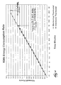
- Fig. 4 illustrates that during a typical heating cycle, approximately 3% less energy is being used as a direct result of using the proportional band control logic. It is possible that this percentage could be increased to approximately 5-5.5% by changing the conduction angle of the triac's firing quadrants, without adversely affecting the performance of the water heater.
- the proportional band control circuit of the present invention prevents overshooting and allows the water temperature to drop only 2°C (5°F) or so to cycle only the needed difference to return the water temperature to a desired setpoint.
- An additional advantage to the proportional band control circuit is its suitability for a flammable vapor environment.
- a flammable vapor environment For example, such an environment may exist in a garage, workshop, or basement storage area wherein solvents, gasoline, propane or other highly flammable or explosive vapors are present.
- Mechanical thermostats and contact type switching devices can arc when an electrical contact is made or broken, depending on the amount of current being switched. The electrical arc can ignite a flammable vapor if the vapor is sufficiently volatile.
- the proportional band control circuit is totally solid state, has no moving parts, and would not ignite flammable vapors.
- logic chips other than the Motorola UAA1016A logic chip may be used to control the on-off cycle of thyristor 103.
- a temperature sensing device other than the thermistor used as temperature sensing device 102 may be employed.
- a thyristor other than a Motorola TRIAC may be used as thyristor 103. Therefore, no limitation of the invention is intended other than limitations contained in the appended claims.
Landscapes
- Control Of Resistance Heating (AREA)
- Heat-Pump Type And Storage Water Heaters (AREA)
- Control Of Temperature (AREA)
- Instantaneous Water Boilers, Portable Hot-Water Supply Apparatuses, And Control Of Portable Hot-Water Supply Apparatuses (AREA)
- Cookers (AREA)
Claims (15)
- Procédé de chauffage de l'eau dans un chauffe-eau (10) du type à accumulation, ayant un élément de chauffage par résistance électrique (16) s'étendant dans une cuve à eau (11) pour chauffer l'eau, ledit procédé comprenant :caractérisé en ce que l'énergie électrique est fournie à l'élément de chauffage par résistance électrique (16) uniquement en salves lors du chauffage de l'eau, chaque salve d'énergie électrique étant suivie d'une période au cours de laquelle aucune énergie électrique n'est conduite au travers de l'élément de chauffage par résistance électrique (16).le stockage d'eau dans la cuve à eau (11) de telle sorte que l'eau puisse être chauffée à une température sélectionnée au cours de périodes d'absence d'usage ;
- Procédé selon la revendication 1, dans lequel l'électricité fournie à l'élément de chauffage par résistance électrique (16) est du courant alternatif ;
la période de chaque salve d'énergie électrique est une fraction de chaque cycle du courant alternatif ;
la période suivant chaque salve d'énergie électrique, au cours de laquelle aucune énergie électrique n'est conduite au travers de l'élément de chauffage par résistance électrique, représente la fraction restante de chaque cycle du courant alternatif. - Procédé selon la revendication 2, dans lequel la période de chaque salve d'énergie électrique représente environ 95 % ou moins de chaque cycle du courant alternatif.
- Chauffe-eau du type à accumulation (10) comprenant :une cuve à eau (11) fermée en permanence pour stocker de l'eau tandis que l'eau est en cours de chauffage jusqu'à une température de consigne ;une conduite d'entrée d'eau (14) pour ajouter de l'eau froide à la cuve à eau ;une conduite de sortie d'eau (15) pour soutirer de l'eau chauffée depuis la cuve à eau ;un élément de chauffage par résistance électrique (16) s'étendant dans la cuve à eau (11) pour chauffer l'eau contenue dans la cuve à eau (11) ; etun régulateur de température (100) pour conduire de l'énergie électrique à l'élément de chauffage par résistance électrique (16) pour chauffer l'eau contenue dans la cuve à eau, l'élément de chauffage étant caractérisé en ce que le régulateur de température (100) ne conduit l'énergie électrique à l'élément de chauffage par résistance électrique (16) que par salves lors du chauffage de l'eau, chaque salve étant suivie d'une période au cours de laquelle aucune énergie électrique n'est conduite à l'élément de chauffage par résistance électrique (16), pour améliorer l'efficacité du chauffage de l'eau dans la cuve à eau.
- Chauffe-eau (10) selon la revendication 4, dans lequel le régulateur de température (100) comprend :un moyen logique (104) pour limiter un cycle, comprenant une salve d'énergie électrique et la période au cours de laquelle aucune énergie électrique n'est conduite, à environ une seconde ou moins, et pour limiter chaque salve d'énergie électrique de façon qu'elle ne représente pas plus d'environ 95 % de chaque cycle.
- Chauffe-eau selon la revendication 4, dans lequel le régulateur de température comprend :un dispositif de consigne de température (18,101) pour établir la température de consigne à laquelle le régulateur de température chauffera l'eau dans la cuve à eau ;un dispositif capteur de température (102) qui capte la température de l'eau dans la cuve à eau ; etun moyen de comparaison de température pour déterminer la différence de température entre la température captée de l'eau et la température de consigne.
- Chauffe-eau selon la revendication 4, dans lequel le régulateur de température (100) comprend :un dispositif à domaine de proportionnalité (104) qui fait passer le régulateur de température (100) d'un état dans lequel le régulateur de température (100) peut conduire l'énergie électrique vers l'élément de chauffage par résistance électrique (16) à un état dans lequel le régulateur de température (100) ne peut pas conduire l'énergie électrique vers l'élément de chauffage par résistance électrique (16).
- Chauffe-eau selon la revendication 7, dans lequel chaque cycle a une période d'environ une seconde ou moins.
- Chauffe-eau selon la revendication 7, dans lequel la proportion de chaque période du cycle au cours de laquelle le régulateur de température (100) conduit l'énergie électrique décroít, tandis que la température captée s'approche plus près de la température de consigne.
- Chauffe-eau selon la revendication 6, dans lequel le régulateur de température (100) comprend :un moyen antagoniste (104,103) qui, après que la température captée atteint la température de consigne, place le régulateur de température à l'état non-conducteur jusqu'à ce que la température captée tombe à une valeur qui représente un différentiel sélectionné d'avec la température de consigne.
- Chauffe-eau selon la revendication 4, dans lequel l'électricité fourni à l'élément de chauffage par résistance électrique (16) est du courant alternatif.
- Chauffe-eau selon la revendication 11, dans lequel la période de chaque salve d'énergie électrique est une fraction de chaque cycle du courant alternatif ; et
la période suivant chaque salve d'énergie électrique, au cours de laquelle aucune énergie électrique n'est conduite au travers de l'élément de chauffage par résistance électrique, représente la fraction restante de chaque cycle du courant alternatif. - Chauffe-eau selon la revendication 10, dans lequel le moyen antagoniste inclut un coupleur opto-électrique (103).
- Chauffe-eau selon la revendication 13, dans lequel le coupleur opto-électrique (103) est conducteur du courant lorsque l'énergie est conduite vers l'élément de chauffage par résistance électrique (16).
- Chauffe-eau selon la revendication 10, dans lequel le moyen antagoniste (104,103) fonctionne pour que la température captée apparaisse au régulateur de température (100) comme étant supérieure à ce qu'elle est, d'une quantité prédéterminée.
Applications Claiming Priority (5)
| Application Number | Priority Date | Filing Date | Title |
|---|---|---|---|
| US118720 | 1987-11-09 | ||
| US914638 | 1997-08-19 | ||
| US08/914,638 US5831250A (en) | 1997-08-19 | 1997-08-19 | Proportional band temperature control with improved thermal efficiency for a water heater |
| US09/118,720 US5948304A (en) | 1997-08-19 | 1998-07-17 | Water heater with proportional band temperature control for improved thermal efficiency |
| PCT/US1998/016175 WO1999009789A1 (fr) | 1997-08-19 | 1998-08-05 | Chauffe-eau a regulation de temperature a bandes proportionnelles permettant d'obtenir un rendement thermique ameliore |
Publications (3)
| Publication Number | Publication Date |
|---|---|
| EP1005784A1 EP1005784A1 (fr) | 2000-06-07 |
| EP1005784A4 EP1005784A4 (fr) | 2002-10-09 |
| EP1005784B1 true EP1005784B1 (fr) | 2004-04-07 |
Family
ID=26816674
Family Applications (1)
| Application Number | Title | Priority Date | Filing Date |
|---|---|---|---|
| EP98938315A Expired - Lifetime EP1005784B1 (fr) | 1997-08-19 | 1998-08-05 | Chauffe-eau a regulation de temperature a bandes proportionnelles permettant d'obtenir un rendement thermique ameliore |
Country Status (8)
| Country | Link |
|---|---|
| EP (1) | EP1005784B1 (fr) |
| JP (1) | JP2001518600A (fr) |
| CN (1) | CN1219416C (fr) |
| AU (1) | AU8686598A (fr) |
| BR (1) | BR9811322A (fr) |
| CA (1) | CA2243797C (fr) |
| DE (1) | DE69823036T2 (fr) |
| WO (1) | WO1999009789A1 (fr) |
Families Citing this family (5)
| Publication number | Priority date | Publication date | Assignee | Title |
|---|---|---|---|---|
| US6363216B1 (en) * | 1999-07-27 | 2002-03-26 | Kenneth A. Bradenbaugh | Water heater having dual side-by-side heating elements |
| JP5852774B2 (ja) * | 2010-07-14 | 2016-02-03 | 株式会社堀場エステック | 液体試料加熱気化装置 |
| WO2012040585A2 (fr) * | 2010-09-23 | 2012-03-29 | Downey Jonathan B | Régulateur thermique adaptatif |
| CN109497828B (zh) * | 2018-11-21 | 2022-07-05 | 浙江绍兴苏泊尔生活电器有限公司 | 电水壶的温度控制方法及装置、电水壶 |
| CN117270597B (zh) * | 2023-09-21 | 2024-07-23 | 深圳市森威尔科技开发股份有限公司 | 一种间歇式控制输出的控温方法及相关设备 |
Citations (1)
| Publication number | Priority date | Publication date | Assignee | Title |
|---|---|---|---|---|
| US4978833A (en) * | 1989-01-27 | 1990-12-18 | Bunn-O-Matic Corporation | Hot water dispenser having improved water temperature control system |
Family Cites Families (4)
| Publication number | Priority date | Publication date | Assignee | Title |
|---|---|---|---|---|
| US3633094A (en) * | 1970-04-15 | 1972-01-04 | Barber Colman Co | Burst length proportioning controller |
| US3878358A (en) * | 1972-11-16 | 1975-04-15 | Xerox Corp | Digital power control |
| NL7610563A (nl) * | 1976-09-22 | 1978-03-29 | Thorn Domestic Appliances Ltd | Luchtdroogtoestel. |
| GB2148467B (en) * | 1983-10-18 | 1988-04-13 | Gainsborough Electrical | Water heaters |
-
1998
- 1998-07-24 CA CA 2243797 patent/CA2243797C/fr not_active Expired - Fee Related
- 1998-08-05 JP JP2000510315A patent/JP2001518600A/ja active Pending
- 1998-08-05 DE DE69823036T patent/DE69823036T2/de not_active Expired - Lifetime
- 1998-08-05 EP EP98938315A patent/EP1005784B1/fr not_active Expired - Lifetime
- 1998-08-05 WO PCT/US1998/016175 patent/WO1999009789A1/fr not_active Ceased
- 1998-08-05 BR BR9811322-4A patent/BR9811322A/pt not_active IP Right Cessation
- 1998-08-05 AU AU86865/98A patent/AU8686598A/en not_active Abandoned
- 1998-08-05 CN CN 98808281 patent/CN1219416C/zh not_active Expired - Fee Related
Patent Citations (1)
| Publication number | Priority date | Publication date | Assignee | Title |
|---|---|---|---|---|
| US4978833A (en) * | 1989-01-27 | 1990-12-18 | Bunn-O-Matic Corporation | Hot water dispenser having improved water temperature control system |
Also Published As
| Publication number | Publication date |
|---|---|
| CA2243797A1 (fr) | 1999-02-19 |
| CA2243797C (fr) | 2005-12-06 |
| CN1219416C (zh) | 2005-09-14 |
| DE69823036D1 (de) | 2004-05-13 |
| DE69823036T2 (de) | 2005-03-10 |
| EP1005784A1 (fr) | 2000-06-07 |
| BR9811322A (pt) | 2001-10-16 |
| JP2001518600A (ja) | 2001-10-16 |
| EP1005784A4 (fr) | 2002-10-09 |
| AU8686598A (en) | 1999-03-08 |
| WO1999009789A1 (fr) | 1999-02-25 |
| CN1267446A (zh) | 2000-09-20 |
Similar Documents
| Publication | Publication Date | Title |
|---|---|---|
| US5948304A (en) | Water heater with proportional band temperature control for improved thermal efficiency | |
| US6374046B1 (en) | Proportional band temperature control for multiple heating elements | |
| US6795644B2 (en) | Water heater | |
| US6455820B2 (en) | Method and apparatus for detecting a dry fire condition in a water heater | |
| US6363216B1 (en) | Water heater having dual side-by-side heating elements | |
| US7346274B2 (en) | Water heater and method of controlling the same | |
| US6560409B2 (en) | Hot water heater stacking reduction control | |
| US7945146B2 (en) | Tankless hot water heater with power modulation | |
| US20100074602A1 (en) | System and method for improved heating of fluid | |
| WO1997025572A9 (fr) | Dispositif et procede de chauffage instantane de fluides | |
| CA1269921A (fr) | Bloc gazeificateur de gaz liquefie | |
| EP0871841A1 (fr) | Dispositif et procede de chauffage instantane de fluides | |
| CA2243797C (fr) | Chauffe-eau avec regulateur de temperature a bande proportionnelle a rendement thermique ameliore | |
| CA1150799A (fr) | Methode et dispositif de regulation de la temperature a l'endroit d'un element chauffant de chauffe-eau | |
| US6424801B1 (en) | Upright cylindrical water heater with top and bottom can covers | |
| MXPA98006695A (en) | Water heater with proportional band temperature control for better thermal performance | |
| JPH11281155A (ja) | 湯沸し装置 | |
| GB2262594A (en) | A boiler | |
| US4720258A (en) | Temperature control means for evaporators | |
| WO2006039740A2 (fr) | Chauffe-eau tete-beche | |
| CA2356516A1 (fr) | Commande programmable de thermostat d'eau chaude | |
| WO1991019311A1 (fr) | Ameliorations apportees au reglage de temperature |
Legal Events
| Date | Code | Title | Description |
|---|---|---|---|
| PUAI | Public reference made under article 153(3) epc to a published international application that has entered the european phase |
Free format text: ORIGINAL CODE: 0009012 |
|
| 17P | Request for examination filed |
Effective date: 20000306 |
|
| AK | Designated contracting states |
Kind code of ref document: A1 Designated state(s): BE DE FR GB NL |
|
| A4 | Supplementary search report drawn up and despatched |
Effective date: 20020822 |
|
| AK | Designated contracting states |
Kind code of ref document: A4 Designated state(s): BE DE FR GB NL |
|
| RIC1 | Information provided on ipc code assigned before grant |
Free format text: 7H 05B 1/02 A, 7F 24H 9/20 B, 7G 05D 23/19 B |
|
| 17Q | First examination report despatched |
Effective date: 20030217 |
|
| GRAP | Despatch of communication of intention to grant a patent |
Free format text: ORIGINAL CODE: EPIDOSNIGR1 |
|
| GRAS | Grant fee paid |
Free format text: ORIGINAL CODE: EPIDOSNIGR3 |
|
| GRAA | (expected) grant |
Free format text: ORIGINAL CODE: 0009210 |
|
| AK | Designated contracting states |
Kind code of ref document: B1 Designated state(s): BE DE FR GB NL |
|
| PG25 | Lapsed in a contracting state [announced via postgrant information from national office to epo] |
Ref country code: FR Free format text: LAPSE BECAUSE OF FAILURE TO SUBMIT A TRANSLATION OF THE DESCRIPTION OR TO PAY THE FEE WITHIN THE PRESCRIBED TIME-LIMIT Effective date: 20040407 |
|
| REG | Reference to a national code |
Ref country code: GB Ref legal event code: FG4D |
|
| REF | Corresponds to: |
Ref document number: 69823036 Country of ref document: DE Date of ref document: 20040513 Kind code of ref document: P |
|
| PGFP | Annual fee paid to national office [announced via postgrant information from national office to epo] |
Ref country code: FR Payment date: 20040819 Year of fee payment: 7 |
|
| PLBE | No opposition filed within time limit |
Free format text: ORIGINAL CODE: 0009261 |
|
| STAA | Information on the status of an ep patent application or granted ep patent |
Free format text: STATUS: NO OPPOSITION FILED WITHIN TIME LIMIT |
|
| EN | Fr: translation not filed | ||
| 26N | No opposition filed |
Effective date: 20050110 |
|
| PGFP | Annual fee paid to national office [announced via postgrant information from national office to epo] |
Ref country code: NL Payment date: 20130826 Year of fee payment: 16 Ref country code: DE Payment date: 20130828 Year of fee payment: 16 |
|
| PGFP | Annual fee paid to national office [announced via postgrant information from national office to epo] |
Ref country code: GB Payment date: 20130827 Year of fee payment: 16 |
|
| PGFP | Annual fee paid to national office [announced via postgrant information from national office to epo] |
Ref country code: BE Payment date: 20130827 Year of fee payment: 16 |
|
| REG | Reference to a national code |
Ref country code: DE Ref legal event code: R119 Ref document number: 69823036 Country of ref document: DE |
|
| REG | Reference to a national code |
Ref country code: NL Ref legal event code: V1 Effective date: 20150301 |
|
| GBPC | Gb: european patent ceased through non-payment of renewal fee |
Effective date: 20140805 |
|
| PG25 | Lapsed in a contracting state [announced via postgrant information from national office to epo] |
Ref country code: BE Free format text: LAPSE BECAUSE OF NON-PAYMENT OF DUE FEES Effective date: 20140831 Ref country code: NL Free format text: LAPSE BECAUSE OF NON-PAYMENT OF DUE FEES Effective date: 20150301 |
|
| PG25 | Lapsed in a contracting state [announced via postgrant information from national office to epo] |
Ref country code: GB Free format text: LAPSE BECAUSE OF NON-PAYMENT OF DUE FEES Effective date: 20140805 Ref country code: DE Free format text: LAPSE BECAUSE OF NON-PAYMENT OF DUE FEES Effective date: 20150303 |