EP1005809B1 - Standfeste, seitlich ausfahrbare Vorrichtung in der Art eines Büros oder eines Tisches - Google Patents
Standfeste, seitlich ausfahrbare Vorrichtung in der Art eines Büros oder eines Tisches Download PDFInfo
- Publication number
- EP1005809B1 EP1005809B1 EP19990403007 EP99403007A EP1005809B1 EP 1005809 B1 EP1005809 B1 EP 1005809B1 EP 19990403007 EP19990403007 EP 19990403007 EP 99403007 A EP99403007 A EP 99403007A EP 1005809 B1 EP1005809 B1 EP 1005809B1
- Authority
- EP
- European Patent Office
- Prior art keywords
- deck
- stabilizer
- shaft
- principal
- assembly according
- Prior art date
- Legal status (The legal status is an assumption and is not a legal conclusion. Google has not performed a legal analysis and makes no representation as to the accuracy of the status listed.)
- Expired - Lifetime
Links
- 239000003381 stabilizer Substances 0.000 claims description 29
- 235000004443 Ricinus communis Nutrition 0.000 claims description 4
- 230000000694 effects Effects 0.000 claims description 4
- 240000000528 Ricinus communis Species 0.000 claims description 3
- 238000006073 displacement reaction Methods 0.000 claims description 3
- 230000000284 resting effect Effects 0.000 claims description 3
- 238000005096 rolling process Methods 0.000 description 13
- 238000003466 welding Methods 0.000 description 3
- 230000000903 blocking effect Effects 0.000 description 2
- 230000006978 adaptation Effects 0.000 description 1
- 238000009434 installation Methods 0.000 description 1
- 239000000463 material Substances 0.000 description 1
- 230000000087 stabilizing effect Effects 0.000 description 1
Images

Classifications
-
- A—HUMAN NECESSITIES
- A47—FURNITURE; DOMESTIC ARTICLES OR APPLIANCES; COFFEE MILLS; SPICE MILLS; SUCTION CLEANERS IN GENERAL
- A47B—TABLES; DESKS; OFFICE FURNITURE; CABINETS; DRAWERS; GENERAL DETAILS OF FURNITURE
- A47B21/00—Tables or desks for office equipment, e.g. typewriters, keyboards
-
- A—HUMAN NECESSITIES
- A47—FURNITURE; DOMESTIC ARTICLES OR APPLIANCES; COFFEE MILLS; SPICE MILLS; SUCTION CLEANERS IN GENERAL
- A47B—TABLES; DESKS; OFFICE FURNITURE; CABINETS; DRAWERS; GENERAL DETAILS OF FURNITURE
- A47B49/00—Revolving cabinets or racks; Cabinets or racks with revolving parts
Definitions
- the invention relates to a deployment assembly stable side usable as desk or table for use private or professional particularly interesting for support for example computer hardware including usually a central unit, a screen and a keyboard, as well as a printer and possibly other items type inverter, modem, speakers, scanners ... etc forming a compact unit called a multimedia station.
- computer hardware including usually a central unit, a screen and a keyboard, as well as a printer and possibly other items type inverter, modem, speakers, scanners ... etc forming a compact unit called a multimedia station.
- One of the objects of the invention is to provide a support for example for computer elements in particular can be easily deployed to create a position quickly operational and perfectly suited to a point user.
- a fixed, rolling or simply movable with stable lateral deployment usable as a desk or as a table well suited for receive for example computer equipment, including at least one main plate cantilevered on its most large dimension and a base mounted, if necessary, on castors with or without locking and multi-directional or similar, supporting said plate by means of a single preferably cylindrical vertical beam formed an outer tubular casing secured to the base, at the interior of which just fits an axis integral with the main tray; this set is remarkable in that that a stabilizer coming to rest on the ground is rigidly fixed to the lower end of the axis which for this purpose extends below the base, the stabilizer being associated with lifting means or authorizing its movement on the ground.
- the one or more trays have a maximum width of 700 mm for transport the assembly between two parts, even if separated by a communication door; on the other hand, the setting place of the multimedia station is easy since it is enough with a simple rotation in the horizontal plane of the plate main upper relative to the base which remains fixed and which can be advantageously used to support for example the central unit or other elements similar bulky items, to quickly provide working position known as the deployed lateral position which is operational, comfortable and very secure despite the overhang that deployment necessarily creates lateral i.e. the rotation in the horizontal plane of the upper shelf around the vertical beam.
- this working configuration can be further improved by adding trays side pivoting around the central beam for constitute, for example, a folding and adjustable seat in height or other accessories such as wire holder, card reader and other devices coming stack on top of the vertical beam.
- this type of furniture which can be fixed or movable for example on casters mounted on its base and whether or not fitted with a known system blocking when stopped, or usable as a stand-alone unit rolling or movable on skid or fixed system and autonomous or even attached, fixed to another piece of furniture.
- rolling assembly according to the invention according to a variant main as shown for example in perspective on figure 1.
- a first horizontal plate 2 of shape overall rectangular, although any other shape perfectly suitable, usable as a tray main job for a user in position seated, mounted cantilever according to its large dimension by means which will be described later, it allowing to rotate in the horizontal plane and incidentally to be adjusted in height, according to any which direction suits the user.
- Beam 1 is secured to a base 3 mounted on a plurality of 4 multidirectional casters, i.e. capable of rotate on itself to take any rolling direction.
- the casters could easily be replaced by skates or any other device to move at least the furniture.
- it is planned to climb on the base 3 a second horizontal plate 5 on which may for example be arranged the central unit of a multimedia station and other heavy accessories, such as than an inverter (not shown in the figures).
- Additional accessories can be advantageously mounted around the cylindrical beam 1: for example it is planned to have between the tray main 2 and the second plate 5 or, a third tray 6 for receiving a printer for example (not shown), or to constitute the support of a seat for the user of the main tray 2 as a table job ; in this case, the plate 6 is advantageously secured to a cylindrical collar 7 coming around the beam 1 to form a guide for the plate 6 both for its height adjustment only for its lateral deployment in rotation around beam 1; naturally, for the blocking in good position of the plate 6, it is provided either a conventional device with counter-tightening by radial screw 8 coming to tighten the collar 7 around the beam 1 either a quick eccentric or cam device or any other similar means.
- a screen holder 9 comes additionally articulate at the upper end of the cylindrical beam 1 via a cap 10 coming to adjust on the end of the beam 1 which allows the screen holder 9 to pivot in all directions of the horizontal plane just above the plateau principal of work 2 for example.
- the cap 10 articulating the support 9 it can be arranged in a passage of wires through beam 1 in order to supply for example a screen on the support 9; the cap 10 is in further processed to finish the dressing of the beam 1 in it giving, as will be explained below, a continuity of cylindrical shape.
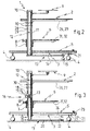
- the beam vertical 1 consists of an external envelope tubular 11 secured to the base 3 in a manner which will specified below, inside which comes just fit an axis 12 secured as it will be detailed next, at the main tray 2 at the top and a stabilizer 13, rigidly fixed at its end lower, coming to rest on the ground in such a way that it helps stabilize the main board 2 especially when the latter is in the deployed lateral position, risking then, by the overhang it generates, tilt the whole assembly.
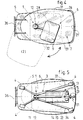
- the stabilizer 13 consists of a horizontal bar extending under the base 3 from the lower end of axis 12 to which it is fixed by any known means, parallel and in the same direction as the great dimension of main tray 2, over a length sufficient to compensate for the effects of the overhang of the main tray 2 when in lateral position deployed (as shown in dotted lines on the figure 4).
- the horizontal bar 14 is provided on the side of its end free, at least one multidirectional caster 15 or an advantageously retractable skate resting on the ground at less when the main tray 2 deploys and / or park in lateral overhang position, according to movement represented by the arrow in figure 4 showing moving the main plate 2 from a position folded (in solid lines) to any position deployed sideways (in dotted lines in Figure 4) and reciprocally.
- the stabilizer 13 can be raised by vertical sliding of the axis 12 in its envelope 11 to eliminate the contact of the stabilizer 13 with the ground and avoid any additional friction when the assembly is moves on its wheels 4.
- the vertical sliding of axis 12 in its envelope 11 is obtained by any means known training such as for example a system with rack 16 ( Figure 3); according to this device axis 12 is equipped over at least a distance corresponding to desired lift of stabilizer 13 of the grooves circular and parallel 17 meshing on a wheel toothed 18 driven by a lever 19 from a position 1 (in solid lines in FIG. 3) corresponding to a low position of stabilizer 13 against the ground until a position 2 (in dotted lines) corresponding to the situation of the stabilizer 13 raised, releasing the castors 15 for moving the rolling assembly on the ground.
- the lifting device can nevertheless be easily adapted to stabilizer 13 of the figure 2 permanently comprising rollers 15 facilitating the rotation of said stabilizer on the ground when you put the tray 2 in the lateral position deployed.
- the latter can be locked in rotation around axis 12 by a cleat springs 21 integral with the base 3 coming to rest engage in a light 22 arranged at the end and on the upper part of the stabilizer 13 ( Figure 1); of this way it is possible to block the stabilizer 13 in the moving position of the rolling assembly so that the plate 2 does not rotate inappropriately around the beam 1 during movement; however, when the assembly must be put in working position, it suffices actuate the cleat 21 downwards for example with a foot to rotate it relative to an axis 23 for lift finger 24 from light 22 and thus release the stabilizer 13 which can then pivot. Cleat 21 is returned to the rest position by a spring 25.
- a horizontal frame for example consisting of two bars coplanar 26,27 ( Figure 4) on which is fixed said tray 2 conventionally formed of a wooden board or similar; these two bars come to converge and join for example by welding to a part cylindrical 28 fixedly mounted around the axis 12 which is extends for this purpose above the envelope 11 on the upper edge 29 from which said piece 28 comes rest or pivot thus determining the height of the plate 2 relative to the base 3; incidentally, the cylindrical part 28 enclosing the axis 12 is secured to the latter for example by a keying transverse 30. It is obvious that one can provide a height adjustment of main tray 2 by joining the two bars 26, 27 by a fixing collar which can, at on request, slide vertically on the part 28.
- connection of the secondary plate 6 collar 7 it is also planned to have two coplanar bars 31.32 (shown in phantom) ends in FIG. 4) coming to converge on the collar 7 to be joined there, for example by welding.
- this consists of two bars 33.34 identical coplanar and having by example a curvature in such a way that they form in the horizontal plane two V mounted head to tail.
- axis 12 can itself be hollow in such a way that can internally circulate cables joining the lower part of the furniture to the upper part with the screen, as already mentioned.
- the outer diameters of the casing 11 of the cylindrical part 28 and the cap 10 ensuring the fixing and orientation of the screen holder 9 are all equal, giving beam 1 an external configuration of smooth cylinder and overall aesthetic particularly advantageous.
- the stabilizer 13 can be covered with a curved plate 35 curved upwards and secured to bars 14 or 20 depending on the execution of the stabilizer 13.
- This curved plate 35 accompanying the movements of the stabilizer 13 and therefore the deployment of the main tray 2 will advantageously serve as a footrest for the user.
- the dimensions of the whole are in relationship with the multimedia material that we hear use, however, the overall width of the trays and including main board 2 should not exceed 700 mm; in this way, at least in the folded position, the set can pass through any door communication between two offices for example.
Landscapes
- Tables And Desks Characterized By Structural Shape (AREA)
- Legs For Furniture In General (AREA)
Claims (10)
- Stabile Konstruktion zum seitlichen Ausfahren, die einen Schreibtisch oder Tisch bildet, wobei sie besonders angepasst ist, um zum Beispiel eine Datenverarbeitungsanlage aufzunehmen, umfassend mindestens eine auf ihrer größten Abmessung im Überstand befindliche Hauptplatte (2) und einen gegebenenfalls auf Möbelrollen (4) mit oder ohne Blockierung beim Halt oder ähnlichem montierten Untersatz (3), der die besagte Platte (2) mittels eines einzigen, vorzugsweise zylindrischen vertikalen Trägers (1) trägt, dadurch gekennzeichnet, dass der einzige Träger (11) aus einem fest mit dem Untersatz (3) verbundenen röhrenförmigen äußeren Mantel (11) besteht, in dessen Innerem eine fest mit der Hauptplatte (2) verbundene Achse genau eingepasst ist, wobei ein sich auf dem Boden abstützender Stabilisator (13) starr am unteren Ende der Achse (12) befestigt ist, die zu diesem Zweck bis unter den Untersatz (3) verlängert ist, wobei der Stabilisator (13) mit Mitteln (15,16) zum Anheben, oder die seine Verschiebung auf dem Boden erlauben, verbunden ist.
- Konstruktion nach dem vorangehenden Anspruch, dadurch gekennzeichnet, dass der Stabilisator (13) aus einer horizontalen Stange (14) besteht, die sich unterhalb des Untersatzes (3) vom unteren Ende der Achse (12), an dem sie durch jegliche bekannten Mittel befestigt ist, parallel und in derselben Richtung wie die Längsabmessung der Hauptplatte (2) über eine ausreichende Länge erstreckt, um die Auswirkungen des Überstandes der Hauptplatte (2), wenn sie sich in ausgefahrener Seitenstellung befindet, zu kompensieren.
- Konstruktion nach Anspruch 2, dadurch gekennzeichnet, dass die untere Verlängerung der Achse derart ist, dass die horizontale Stange (20), vorzugsweise von quadratischem Querschnitt, zumindest dann entlang ihrer gesamten Länge auf dem Boden aufliegt, wenn sich die Hauptplatte in ausgefahrener Seitenstellung befindet.
- Konstruktion nach Anspruch 2, dadurch gekennzeichnet, dass die horizontale Stange (14) auf der Seite ihres freien Endes mit mindestens einer Möbelrolle (15) oder mit einer vorteilhafter Weise einklappbaren Kufe versehen ist, die zumindest dann auf dem Boden aufliegt, wenn die Hauptplatte (2) in die Seitenstellung ausgefahren wird und/oder in dieser verweilt.
- Konstruktion nach einem der Ansprüche 1 bis 4, dadurch gekennzeichnet, dass wenn sich die Hauptplatte (2) nicht in ausgefahrener Seitenstellung befindet, der Stabilisator (13) durch eine Axialverschiebung der Achse (12) in ihrem Mantel (11) mittels jeglicher bekannter Antriebsmittel, wie zum Beispiel einem Zahnstangensystem (16,17), angehoben werden kann, um die Berührung mit dem Boden zu vermeiden.
- Konstruktion nach einem der vorangehenden Ansprüche, dadurch gekennzeichnet, dass man die Verbindung der Hauptplatte (2) mit der Achse (12) erhält durch das Zusammenwirken eines horizontalen Gestells, zum Beispiel bestehend aus zwei in einer Ebene liegenden Stangen (26,27), auf denen die besagte Platte (2) befestigt ist und die auf einem zylindrischen Teil (28) zusammenlaufen, das fest um die Achse (12) herum angebracht ist, die zu diesem Zweck oberhalb des Mantels (11) verlängert ist, auf dessen oberem Abschnitt (29) das besagte Teil (28) aufliegt oder sich dreht, womit die Höhe der Platte (2) in Bezug zum Untersatz (3) festgelegt wird, wobei die Außendurchmesser des besagten zylindrischen Teils (28) und des Mantels (11) vorteilhafter Weise dieselben sind.
- Konstruktion nach einem der vorangehenden Ansprüche, dadurch gekennzeichnet, dass verschiedene Nebenplatten (5,6,9) oder Zubehörteile um den zylindrischen Träger (1) herum angeordnet sein können, wobei sie fest (5), halbfest (6), insbesondere in der Höhe, oder um den Träger (1) schwenkbar sind, je nachdem ob sie jeweils fest mit dem Mantel (11) verbunden, durch jegliche bekannten Mittel, wie einen Ring (7) zum schnellen Festklemmen (8), festgeklemmt angebracht, oder direkt oder mittels eines zylindrischen Teils (28) fest mit der Achse (12) verbunden sind.
- Konstruktion nach einem der vorangehenden Ansprüche, dadurch gekennzeichnet, dass der Stabilisator (13), was die Drehung um die Achse (12) angeht, durch einen fest mit dem Untersatz (3) verbundenen Federstopper (21) arretiert werden kann, der unbetätigt in eine entsprechende Einführöffnung (22) des Stabilisators (13) eingreift.
- Konstruktion nach einem der vorangehenden Ansprüche, dadurch gekennzeichnet, dass die Achse (12) hohl ist, um als Durchzug für Stromkabel zwischen den unteren Teil der Konstruktion und dem zum Beispiel einen Bildschirm tragenden oberen Teil (9) zu dienen.
- Konstruktion nach einem der vorangehenden Ansprüche, dadurch gekennzeichnet, dass der Stabilisator (13) nach oben zu mit einer gebogenen Platte (35) bedeckt ist, um als Fußstütze zu dienen, wenn sich die Hauptplatte (2) in ausgefahrener Seitenstellung befindet.
Applications Claiming Priority (2)
| Application Number | Priority Date | Filing Date | Title |
|---|---|---|---|
| FR9815278A FR2786677B1 (fr) | 1998-12-03 | 1998-12-03 | Ensemble a deploiement lateral stable du genre bureau ou table |
| FR9815278 | 1998-12-03 |
Publications (2)
| Publication Number | Publication Date |
|---|---|
| EP1005809A1 EP1005809A1 (de) | 2000-06-07 |
| EP1005809B1 true EP1005809B1 (de) | 2003-05-02 |
Family
ID=9533542
Family Applications (1)
| Application Number | Title | Priority Date | Filing Date |
|---|---|---|---|
| EP19990403007 Expired - Lifetime EP1005809B1 (de) | 1998-12-03 | 1999-12-02 | Standfeste, seitlich ausfahrbare Vorrichtung in der Art eines Büros oder eines Tisches |
Country Status (3)
| Country | Link |
|---|---|
| EP (1) | EP1005809B1 (de) |
| DE (1) | DE69907379D1 (de) |
| FR (1) | FR2786677B1 (de) |
Cited By (1)
| Publication number | Priority date | Publication date | Assignee | Title |
|---|---|---|---|---|
| CN110235079A (zh) * | 2017-01-27 | 2019-09-13 | 威欧.艾姆伊有限公司 | 滚动装置和利用集成式滚动装置使设备自主重新定位的方法 |
Families Citing this family (4)
| Publication number | Priority date | Publication date | Assignee | Title |
|---|---|---|---|---|
| NO20003338A (no) * | 2000-06-27 | 2001-02-19 | Helle Aadne | Anordning ved frittstående bord |
| CN107125921A (zh) * | 2017-06-23 | 2017-09-05 | 震旦(中国)有限公司 | 一种桌子 |
| JP6814526B2 (ja) * | 2018-04-03 | 2021-01-20 | ニトリ ファニチャー ベトナムNitori Furniture Vietnam Epe | 転倒防止具およびこれを具備する箪笥 |
| CN112515360B (zh) * | 2020-11-30 | 2022-07-01 | 重庆数宜信信用管理有限公司 | 一种带高拍仪的办公桌 |
Family Cites Families (3)
| Publication number | Priority date | Publication date | Assignee | Title |
|---|---|---|---|---|
| DE2344663A1 (de) * | 1973-09-05 | 1975-03-13 | Siegfried Burkhardt | Arbeitsplatz |
| US4836624A (en) * | 1988-04-05 | 1989-06-06 | Intellistor, Inc. | Anti-tip device |
| US5230408A (en) * | 1992-05-11 | 1993-07-27 | Imports By Brian Incorporated | Automatically extending anti tip-over device for wheeled luggage |
-
1998
- 1998-12-03 FR FR9815278A patent/FR2786677B1/fr not_active Expired - Fee Related
-
1999
- 1999-12-02 DE DE69907379T patent/DE69907379D1/de not_active Expired - Lifetime
- 1999-12-02 EP EP19990403007 patent/EP1005809B1/de not_active Expired - Lifetime
Cited By (1)
| Publication number | Priority date | Publication date | Assignee | Title |
|---|---|---|---|---|
| CN110235079A (zh) * | 2017-01-27 | 2019-09-13 | 威欧.艾姆伊有限公司 | 滚动装置和利用集成式滚动装置使设备自主重新定位的方法 |
Also Published As
| Publication number | Publication date |
|---|---|
| FR2786677A1 (fr) | 2000-06-09 |
| EP1005809A1 (de) | 2000-06-07 |
| DE69907379D1 (de) | 2003-06-05 |
| FR2786677B1 (fr) | 2001-01-12 |
Similar Documents
| Publication | Publication Date | Title |
|---|---|---|
| EP0915691B1 (de) | Mobile und schwenkbare kreisplattform zum transferieren einer körperbehinderten person | |
| EP4056241A1 (de) | Ausrüstung zum praktizieren von basketball | |
| FR3066223A1 (fr) | Systeme de fixation de roulette escamotable de marchepied, et marchepied comprenant au moins un systeme de fixation de roulette escamotable | |
| FR2508291A1 (fr) | Meuble comportant un plateau reglable pour l'amenagement d'un poste de travail en construction modulaire | |
| FR2649372A1 (fr) | Siege a dossier reversible | |
| EP1005809B1 (de) | Standfeste, seitlich ausfahrbare Vorrichtung in der Art eines Büros oder eines Tisches | |
| EP0204637A1 (de) | Bewegliche Werkbank mit rein mechanischen Bewegungsmitteln | |
| EP1386031A1 (de) | Höhenverstellbarer bügeltisch | |
| FR2976791A1 (fr) | Barriere de lit escamotable | |
| FR2832676A1 (fr) | Siege de vehicule automobile a console integree | |
| FR2723688A1 (fr) | Lit basculant a trois positions | |
| EP4056242A1 (de) | Ausrüstung zum praktizieren von basketball | |
| EP4493446B1 (de) | Sattelstützenanordnung | |
| EP0818983A1 (de) | Sessel mit integrierter aufrichtvorrichtung | |
| WO2019180654A1 (fr) | Dispositif d'aide au passage de la position assise à la position debout, et inversement, plateforme de mobilité pour siège comprenant un tel dispositif, et siège roulant | |
| FR2698252A1 (fr) | Meuble-lit. | |
| EP1057595A1 (de) | Zusammenklappbarer Arbeitsbock | |
| FR2649659A1 (fr) | Chariot pliant | |
| FR3036024A1 (fr) | Dispositif d'appui assis-debout et poste de travail manuel equipe de celui-ci | |
| FR2762977A1 (fr) | Table a rallonges | |
| FR3066686B1 (fr) | Dispositif d’appui assis-debout et poste de travail manuel equipe de celui-ci | |
| WO2023242432A1 (fr) | Table pliable a pieds telescopiques | |
| FR2754877A1 (fr) | Pietement autostable a quatre pieds | |
| FR2841754A1 (fr) | Systeme de tete de lit articulee et procede pour articuler une tete de lit en utilisant le systeme | |
| FR2559363A1 (fr) | Lit pliant |
Legal Events
| Date | Code | Title | Description |
|---|---|---|---|
| PUAI | Public reference made under article 153(3) epc to a published international application that has entered the european phase |
Free format text: ORIGINAL CODE: 0009012 |
|
| AK | Designated contracting states |
Kind code of ref document: A1 Designated state(s): BE DE FR NL |
|
| AX | Request for extension of the european patent |
Free format text: AL;LT;LV;MK;RO;SI |
|
| 17P | Request for examination filed |
Effective date: 20001012 |
|
| AKX | Designation fees paid |
Free format text: BE DE FR NL |
|
| GRAH | Despatch of communication of intention to grant a patent |
Free format text: ORIGINAL CODE: EPIDOS IGRA |
|
| GRAH | Despatch of communication of intention to grant a patent |
Free format text: ORIGINAL CODE: EPIDOS IGRA |
|
| GRAA | (expected) grant |
Free format text: ORIGINAL CODE: 0009210 |
|
| AK | Designated contracting states |
Designated state(s): BE DE FR NL |
|
| PG25 | Lapsed in a contracting state [announced via postgrant information from national office to epo] |
Ref country code: NL Free format text: LAPSE BECAUSE OF FAILURE TO SUBMIT A TRANSLATION OF THE DESCRIPTION OR TO PAY THE FEE WITHIN THE PRESCRIBED TIME-LIMIT Effective date: 20030502 |
|
| REF | Corresponds to: |
Ref document number: 69907379 Country of ref document: DE Date of ref document: 20030605 Kind code of ref document: P |
|
| PG25 | Lapsed in a contracting state [announced via postgrant information from national office to epo] |
Ref country code: DE Free format text: LAPSE BECAUSE OF FAILURE TO SUBMIT A TRANSLATION OF THE DESCRIPTION OR TO PAY THE FEE WITHIN THE PRESCRIBED TIME-LIMIT Effective date: 20030805 |
|
| NLV1 | Nl: lapsed or annulled due to failure to fulfill the requirements of art. 29p and 29m of the patents act | ||
| PGFP | Annual fee paid to national office [announced via postgrant information from national office to epo] |
Ref country code: FR Payment date: 20031230 Year of fee payment: 5 |
|
| PGFP | Annual fee paid to national office [announced via postgrant information from national office to epo] |
Ref country code: BE Payment date: 20040116 Year of fee payment: 5 |
|
| PLBE | No opposition filed within time limit |
Free format text: ORIGINAL CODE: 0009261 |
|
| STAA | Information on the status of an ep patent application or granted ep patent |
Free format text: STATUS: NO OPPOSITION FILED WITHIN TIME LIMIT |
|
| 26N | No opposition filed |
Effective date: 20040203 |
|
| PG25 | Lapsed in a contracting state [announced via postgrant information from national office to epo] |
Ref country code: BE Free format text: LAPSE BECAUSE OF NON-PAYMENT OF DUE FEES Effective date: 20041231 |
|
| BERE | Be: lapsed |
Owner name: *NARBUR SAS Effective date: 20041231 |
|
| PG25 | Lapsed in a contracting state [announced via postgrant information from national office to epo] |
Ref country code: FR Free format text: LAPSE BECAUSE OF NON-PAYMENT OF DUE FEES Effective date: 20050831 |
|
| REG | Reference to a national code |
Ref country code: FR Ref legal event code: ST |
|
| BERE | Be: lapsed |
Owner name: *NARBUR SAS Effective date: 20041231 |