EP1005823A1 - Elément tubulaire d'aspiration pour un aspirateur - Google Patents
Elément tubulaire d'aspiration pour un aspirateur Download PDFInfo
- Publication number
- EP1005823A1 EP1005823A1 EP99123599A EP99123599A EP1005823A1 EP 1005823 A1 EP1005823 A1 EP 1005823A1 EP 99123599 A EP99123599 A EP 99123599A EP 99123599 A EP99123599 A EP 99123599A EP 1005823 A1 EP1005823 A1 EP 1005823A1
- Authority
- EP
- European Patent Office
- Prior art keywords
- suction
- suction pipe
- tool
- pipe part
- suction tool
- Prior art date
- Legal status (The legal status is an assumption and is not a legal conclusion. Google has not performed a legal analysis and makes no representation as to the accuracy of the status listed.)
- Granted
Links
Images
Classifications
-
- A—HUMAN NECESSITIES
- A47—FURNITURE; DOMESTIC ARTICLES OR APPLIANCES; COFFEE MILLS; SPICE MILLS; SUCTION CLEANERS IN GENERAL
- A47L—DOMESTIC WASHING OR CLEANING; SUCTION CLEANERS IN GENERAL
- A47L9/00—Details or accessories of suction cleaners, e.g. mechanical means for controlling the suction or for effecting pulsating action; Storing devices specially adapted to suction cleaners or parts thereof; Carrying-vehicles specially adapted for suction cleaners
- A47L9/02—Nozzles
Definitions
- the invention relates to a suction pipe part for a vacuum cleaner, on which an additional Suction tool is held such that it is optionally in a working or rest position is feasible.
- Such a suction pipe part is known from DE-U-90 03 441.
- Suction pipe part is a separate holding part in the area of its suction end appropriate.
- An additional suction tool is articulated on this holding part in such a way that this can be pivoted from a rest position into a working position. In the Working position, the suction tool is then sealed to the suction opening of the Coupled intake manifold.
- This suction tool is available during suction work immediately available and can be used quickly by simply swiveling it become.
- the disadvantage is that the additional suction tool is relatively in its rest position bulky protrudes on the intake manifold part and thus during suction work without the additional suction tools can be disrupted. It also arises from separate holding part a not inconsiderable assembly and material expenditure.
- the invention is based, so a suction pipe part for a vacuum cleaner the task shape that for attaching an additional suction tool no separate Holding part is required.
- Suction tool in the area of the suction-side end of the suction tube part the intake manifold part is arranged.
- the additional suction tool can thus if necessary can be moved to its work or rest position by simply moving it.
- the suction tool encircles the suction pipe part circumferentially interferes with it when working the suction tube part alone, since the suction tool only makes a slight difference Increase in diameter of the intake manifold part is caused.
- the suction tool is longitudinally divided at least over part of its length and the sections of the suction tool formed by the longitudinal division in it Working position joined together circumferentially by means of an elastic element can be held in the additional suction tool in its working position in cross-section smaller suction opening than the suction opening of the suction pipe part be created. This can have the effect with the additional suction tool a crevice nozzle can be achieved.
- the elastic element is tubular and pushed over the sections.
- the elastic element can be a rubber hose.
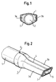
- suction pipe part 1 with a suction pipe part is designated, in which in the area of its intake opening 2 additional suction tool 3 is pushed onto the suction pipe part 1 on the outside.
- the additional suction tool 3 is by a longitudinal division 4 in at least two each other opposite sections 3a and 3b divided.
- sections 3a and 3b are connected to each other. This is in the area of this end of the suction tool 3 circumferentially closed plug-in opening is formed, with which the suction tool 3 in can be simply plugged onto the intake manifold part 1.
- the displacement route of the suction tool 3 on the intake manifold part 1 can by suitable stop members be limited in both work and rest positions.
- an elastic element 7 e.g. a rubber ring on the Outer circumference attached.
- a rubber hose can also be used be plugged onto the suction tool 3.
- Such can advantageously Extend rubber hose over the entire length of the suction tool 3, which in the working position of the suction tool 3 a good seal on the circumference of the the rubber hose pressed sections 3a and 3b is reached.
- Suction tool 3 By pushing the suction tool 3 back onto the suction pipe part 1, this can be done Suction tool 3 are brought into its rest position.
- the sections 3a and 3b due to the elasticity of the elastic element 7 are pressed apart so that the Suction pipe part 1 can occur between sections 3a and 3b.
- This will be the Intake opening 2 of the intake pipe part 1 accessible. It can then on the one hand with this Suction opening 2 can be sucked directly.
- another can Suction pipe or a suction hose can be coupled to the suction opening 5.
- the suction tool 3 plugged onto the suction pipe part 1 stands for the implementation of appropriate suction work immediately available.
- plugged in the suction tool 3 is hardly a hindrance when not in use, since it is only a relative one slight increase in diameter of the outer circumference of the intake manifold part 1 caused.
Landscapes
- Engineering & Computer Science (AREA)
- Mechanical Engineering (AREA)
- Nozzles For Electric Vacuum Cleaners (AREA)
- Electric Vacuum Cleaner (AREA)
Applications Claiming Priority (2)
| Application Number | Priority Date | Filing Date | Title |
|---|---|---|---|
| DE19855907A DE19855907A1 (de) | 1998-12-03 | 1998-12-03 | Saugrohrteil für einen Staubsauger |
| DE19855907 | 1998-12-03 |
Publications (2)
| Publication Number | Publication Date |
|---|---|
| EP1005823A1 true EP1005823A1 (fr) | 2000-06-07 |
| EP1005823B1 EP1005823B1 (fr) | 2003-08-13 |
Family
ID=7889919
Family Applications (1)
| Application Number | Title | Priority Date | Filing Date |
|---|---|---|---|
| EP99123599A Expired - Lifetime EP1005823B1 (fr) | 1998-12-03 | 1999-11-26 | Elément tubulaire d'aspiration pour un aspirateur |
Country Status (2)
| Country | Link |
|---|---|
| EP (1) | EP1005823B1 (fr) |
| DE (2) | DE19855907A1 (fr) |
Families Citing this family (1)
| Publication number | Priority date | Publication date | Assignee | Title |
|---|---|---|---|---|
| DE102010040056B4 (de) | 2010-08-31 | 2017-04-06 | BSH Hausgeräte GmbH | Saugrohrteil eines Staubsaugers |
Citations (5)
| Publication number | Priority date | Publication date | Assignee | Title |
|---|---|---|---|---|
| US2038424A (en) * | 1933-07-18 | 1936-04-21 | Electrolux Corp | Nozzle for vacuum cleaners |
| DE632190C (de) * | 1934-05-17 | 1936-07-03 | Josepha Schlingmann Geb Gollin | Saugmundstueck fuer Staubsauger |
| DE2052606A1 (de) * | 1970-10-27 | 1972-05-04 | Siemens Elektrogeraete Gmbh | Staubsaugerduse |
| DE9003441U1 (de) * | 1990-03-23 | 1990-06-13 | Siemens AG, 1000 Berlin und 8000 München | Saugrohr für einen Staubsauger |
| DE9210227U1 (de) * | 1992-07-30 | 1993-12-02 | Siemens AG, 80333 München | Fugendüse |
Family Cites Families (1)
| Publication number | Priority date | Publication date | Assignee | Title |
|---|---|---|---|---|
| DE8004490U1 (de) * | 1980-02-20 | 1980-05-22 | Siemens Ag, 1000 Berlin Und 8000 Muenchen | Staubsaugerwerkzeug |
-
1998
- 1998-12-03 DE DE19855907A patent/DE19855907A1/de not_active Withdrawn
-
1999
- 1999-11-26 EP EP99123599A patent/EP1005823B1/fr not_active Expired - Lifetime
- 1999-11-26 DE DE59906576T patent/DE59906576D1/de not_active Expired - Lifetime
Patent Citations (5)
| Publication number | Priority date | Publication date | Assignee | Title |
|---|---|---|---|---|
| US2038424A (en) * | 1933-07-18 | 1936-04-21 | Electrolux Corp | Nozzle for vacuum cleaners |
| DE632190C (de) * | 1934-05-17 | 1936-07-03 | Josepha Schlingmann Geb Gollin | Saugmundstueck fuer Staubsauger |
| DE2052606A1 (de) * | 1970-10-27 | 1972-05-04 | Siemens Elektrogeraete Gmbh | Staubsaugerduse |
| DE9003441U1 (de) * | 1990-03-23 | 1990-06-13 | Siemens AG, 1000 Berlin und 8000 München | Saugrohr für einen Staubsauger |
| DE9210227U1 (de) * | 1992-07-30 | 1993-12-02 | Siemens AG, 80333 München | Fugendüse |
Also Published As
| Publication number | Publication date |
|---|---|
| DE59906576D1 (de) | 2003-09-18 |
| EP1005823B1 (fr) | 2003-08-13 |
| DE19855907A1 (de) | 2000-06-08 |
Similar Documents
| Publication | Publication Date | Title |
|---|---|---|
| DE60310053T2 (de) | Scheibenwischvorrichtung | |
| EP1894508B1 (fr) | Aspirateur doté d'un manche et d'un adaptateur | |
| DE2401037B1 (de) | Rohrstück für Reinigungsmaschinen, insbesondere für Staub- oder Flüssigkeitssauggeräte | |
| DE3546340C2 (de) | Bürste zum Reinigen der Oberfläche rohrförmiger Körper | |
| DE2142068A1 (de) | Schlauch, insbesondere staubsaugerschlauch | |
| EP1396221B1 (fr) | Buse pour aspirateur | |
| DE102010040056B4 (de) | Saugrohrteil eines Staubsaugers | |
| DE19855907A1 (de) | Saugrohrteil für einen Staubsauger | |
| DE3529133C2 (fr) | ||
| DE29610327U1 (de) | An ein Saugrohr ankoppelbares Mehrzweck-Saugmundstück | |
| DE844050C (de) | Umleitstutzen fuer Staubsauger | |
| DE29918292U1 (de) | Leerrohrhalter | |
| DE102005049271B4 (de) | Verbindungselement zur Aufnahme von Schläuchen | |
| EP0229087A1 (fr) | Tuyauterie souple | |
| AT402682B (de) | Düse für staubsauger mit abnehmbarer bodendüse | |
| DE3717993C2 (fr) | ||
| DE4309495A1 (de) | Staubsaugerschlauch | |
| DE2748512A1 (de) | Abzweigarmatur fuer rohre, insbesondere fuer bewaesserungsanlagen | |
| EP1924182B1 (fr) | Buse d'aspirateur | |
| EP1795104B1 (fr) | Tuyau télescopique d'aspirateur avec coulisse de rallongement du rail | |
| DE1600555B2 (de) | Vorrichtung zum verbinden aneinanderstossender gegenstaende | |
| CH639183A5 (de) | Rohrverbindung. | |
| DE1405755C (de) | Losbare Verbindung zwischen einem mit einem Anschlag versehenen Wischerarm und einem Wischblatt fur Scheibenwischer, ins besondere von Kraftfahrzeugen | |
| DE2327922C3 (de) | Stiel für Teppichkehrer und dgl | |
| DE1934184A1 (de) | Teleskopierbare Foerderleitung,insbesondere fuer Staubsauger |
Legal Events
| Date | Code | Title | Description |
|---|---|---|---|
| PUAI | Public reference made under article 153(3) epc to a published international application that has entered the european phase |
Free format text: ORIGINAL CODE: 0009012 |
|
| AK | Designated contracting states |
Kind code of ref document: A1 Designated state(s): DE FR GB IT |
|
| AX | Request for extension of the european patent |
Free format text: AL;LT;LV;MK;RO;SI |
|
| 17P | Request for examination filed |
Effective date: 20001120 |
|
| AKX | Designation fees paid |
Free format text: DE FR GB IT |
|
| 17Q | First examination report despatched |
Effective date: 20020320 |
|
| GRAH | Despatch of communication of intention to grant a patent |
Free format text: ORIGINAL CODE: EPIDOS IGRA |
|
| GRAH | Despatch of communication of intention to grant a patent |
Free format text: ORIGINAL CODE: EPIDOS IGRA |
|
| GRAA | (expected) grant |
Free format text: ORIGINAL CODE: 0009210 |
|
| AK | Designated contracting states |
Designated state(s): DE FR GB IT |
|
| REG | Reference to a national code |
Ref country code: GB Ref legal event code: FG4D Free format text: NOT ENGLISH |
|
| RIN1 | Information on inventor provided before grant (corrected) |
Inventor name: BUETTNER, MARIA Inventor name: KESS, HERBERT Inventor name: RAEDER, SEBASTIAN Inventor name: JESSENBERGER, MARTIN Inventor name: EYRING, STEFAN Inventor name: SCHROETER, JOERG Inventor name: SCHOEPPNER, SYLVIA |
|
| REF | Corresponds to: |
Ref document number: 59906576 Country of ref document: DE Date of ref document: 20030918 Kind code of ref document: P |
|
| GBT | Gb: translation of ep patent filed (gb section 77(6)(a)/1977) |
Effective date: 20031127 |
|
| RAP2 | Party data changed (patent owner data changed or rights of a patent transferred) |
Owner name: BSH BOSCH UND SIEMENS HAUSGERAETE GMBH |
|
| ET | Fr: translation filed | ||
| PLBE | No opposition filed within time limit |
Free format text: ORIGINAL CODE: 0009261 |
|
| STAA | Information on the status of an ep patent application or granted ep patent |
Free format text: STATUS: NO OPPOSITION FILED WITHIN TIME LIMIT |
|
| 26N | No opposition filed |
Effective date: 20040514 |
|
| PGFP | Annual fee paid to national office [announced via postgrant information from national office to epo] |
Ref country code: IT Payment date: 20081127 Year of fee payment: 10 |
|
| PGFP | Annual fee paid to national office [announced via postgrant information from national office to epo] |
Ref country code: FR Payment date: 20081118 Year of fee payment: 10 |
|
| PGFP | Annual fee paid to national office [announced via postgrant information from national office to epo] |
Ref country code: GB Payment date: 20081121 Year of fee payment: 10 |
|
| GBPC | Gb: european patent ceased through non-payment of renewal fee |
Effective date: 20091126 |
|
| REG | Reference to a national code |
Ref country code: FR Ref legal event code: ST Effective date: 20100730 |
|
| PG25 | Lapsed in a contracting state [announced via postgrant information from national office to epo] |
Ref country code: FR Free format text: LAPSE BECAUSE OF NON-PAYMENT OF DUE FEES Effective date: 20091130 |
|
| PG25 | Lapsed in a contracting state [announced via postgrant information from national office to epo] |
Ref country code: GB Free format text: LAPSE BECAUSE OF NON-PAYMENT OF DUE FEES Effective date: 20091126 |
|
| PG25 | Lapsed in a contracting state [announced via postgrant information from national office to epo] |
Ref country code: IT Free format text: LAPSE BECAUSE OF NON-PAYMENT OF DUE FEES Effective date: 20091126 |
|
| REG | Reference to a national code |
Ref country code: DE Ref legal event code: R081 Ref document number: 59906576 Country of ref document: DE Owner name: BSH HAUSGERAETE GMBH, DE Free format text: FORMER OWNER: BSH BOSCH UND SIEMENS HAUSGERAETE GMBH, 81739 MUENCHEN, DE Effective date: 20150402 |
|
| PGFP | Annual fee paid to national office [announced via postgrant information from national office to epo] |
Ref country code: DE Payment date: 20171130 Year of fee payment: 19 |
|
| REG | Reference to a national code |
Ref country code: DE Ref legal event code: R119 Ref document number: 59906576 Country of ref document: DE |
|
| PG25 | Lapsed in a contracting state [announced via postgrant information from national office to epo] |
Ref country code: DE Free format text: LAPSE BECAUSE OF NON-PAYMENT OF DUE FEES Effective date: 20190601 |