EP1005875B1 - Liquidinfusionsvorrichtung - Google Patents
Liquidinfusionsvorrichtung Download PDFInfo
- Publication number
- EP1005875B1 EP1005875B1 EP19990309480 EP99309480A EP1005875B1 EP 1005875 B1 EP1005875 B1 EP 1005875B1 EP 19990309480 EP19990309480 EP 19990309480 EP 99309480 A EP99309480 A EP 99309480A EP 1005875 B1 EP1005875 B1 EP 1005875B1
- Authority
- EP
- European Patent Office
- Prior art keywords
- plunger
- slider
- flange
- holding means
- infusion apparatus
- Prior art date
- Legal status (The legal status is an assumption and is not a legal conclusion. Google has not performed a legal analysis and makes no representation as to the accuracy of the status listed.)
- Expired - Lifetime
Links
Images


Classifications
-
- A—HUMAN NECESSITIES
- A61—MEDICAL OR VETERINARY SCIENCE; HYGIENE
- A61M—DEVICES FOR INTRODUCING MEDIA INTO, OR ONTO, THE BODY; DEVICES FOR TRANSDUCING BODY MEDIA OR FOR TAKING MEDIA FROM THE BODY; DEVICES FOR PRODUCING OR ENDING SLEEP OR STUPOR
- A61M5/00—Devices for bringing media into the body in a subcutaneous, intra-vascular or intramuscular way; Accessories therefor, e.g. filling or cleaning devices, arm-rests
- A61M5/14—Infusion devices, e.g. infusing by gravity; Blood infusion; Accessories therefor
- A61M5/142—Pressure infusion, e.g. using pumps
- A61M5/145—Pressure infusion, e.g. using pumps using pressurised reservoirs, e.g. pressurised by means of pistons
- A61M5/1452—Pressure infusion, e.g. using pumps using pressurised reservoirs, e.g. pressurised by means of pistons pressurised by means of pistons
- A61M5/1456—Pressure infusion, e.g. using pumps using pressurised reservoirs, e.g. pressurised by means of pistons pressurised by means of pistons with a replaceable reservoir comprising a piston rod to be moved into the reservoir, e.g. the piston rod is part of the removable reservoir
-
- A—HUMAN NECESSITIES
- A61—MEDICAL OR VETERINARY SCIENCE; HYGIENE
- A61M—DEVICES FOR INTRODUCING MEDIA INTO, OR ONTO, THE BODY; DEVICES FOR TRANSDUCING BODY MEDIA OR FOR TAKING MEDIA FROM THE BODY; DEVICES FOR PRODUCING OR ENDING SLEEP OR STUPOR
- A61M5/00—Devices for bringing media into the body in a subcutaneous, intra-vascular or intramuscular way; Accessories therefor, e.g. filling or cleaning devices, arm-rests
- A61M5/14—Infusion devices, e.g. infusing by gravity; Blood infusion; Accessories therefor
- A61M5/142—Pressure infusion, e.g. using pumps
- A61M5/145—Pressure infusion, e.g. using pumps using pressurised reservoirs, e.g. pressurised by means of pistons
- A61M5/1452—Pressure infusion, e.g. using pumps using pressurised reservoirs, e.g. pressurised by means of pistons pressurised by means of pistons
- A61M5/1458—Means for capture of the plunger flange
Definitions
- the present invention relates to a liquid infusion apparatus, and more particularly, relates to a liquid infusion apparatus for infusing liquid such as a liquid medicine or blood into a human body by pushing a plunger into a syringe by the rotation of a prim mover, said liquid infusion apparatus having a holding device for holding said plunger.
- the present invention is based on the invention of the Japanese Patent Laid-Open No. 192399/1998.
- FIGS. 2A and 2B show a liquid infusion apparatus of said prior art, wherein reference numeral 1 is a syringe, 2 is a plunger, 2-1 is a flange of the plunger 2, 3 is a slider, 3-1 is a contact face of the slider 3, 3-2 is a front wall of the slider 3, 4-1 is a push button, 5 is a holding arm for holding said flange 2-1 of the plunger 2, which is movable in a moving direction of said slider 3 and rotatable around the axis thereof, 5-1 is a supporting shaft of the holding arm 5, 5-2 is a screw grove formed on the supporting shaft 5-1, 3-3 is a bearing formed on the slider 3 for supporting said supporting shaft 5-1, 3-4 is a through hole formed on said front wall 3-2 for the supporting shaft 5-1, 6 is a lever for driving said supporting shaft 5-1, 6-1 is a pivot shaft for the lever 6, 6-2 is an engaging pin projected from the side surface of the lever 6 for engaging with the screw groove 5-2, and 7
- Two of said holding arms 5 are provided so as to be rotated in the opposite directions, respectively at the same time by the push button 4-1 to open the holding arms 5 or to close the same:
- the flange 2-1 of the plunger 2 is urged toward the contact face 3-1 of the slider 3 when the holding arms 5 is closed as shown in FIG. 2B and moved toward the slider 3 by the return spring 7.
- FIGS. 2A and 2B show a state that the flange 2-1 of the plunger 2 is held by the holding arms 5, and FIGS. 3A and 3B show a state that the flange 2-1 of the plunger 2 is not yet held by the holding arms 5.
- FIG. 4 is a state that the flange 2-1 of the plunger 2 is held and brought into contact with the contact face 3-1 of the slider 3 by the action of the holding arms 5.
- the flange 2-1 of the plunger is positioned between the holding arms 5 and the contact face 3-1 of the slider 3.
- the workability can be enhanced when the syringe 1 is installed.
- the plunger 2 is sucked into the syringe 1 if the sucking force is larger than the spring force of the return spring 7, so that undesirable exceed liquid is injected into the human body.
- An object of the present invention is to obviate such defect.
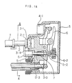
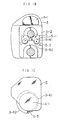
- the through hole 3-4 is formed of a semi-circular hole portion 3-41 of a small diameter and a semi-circular hole portion 3-42 of a large diameter, the supporting shaft 5-1 of said holding arm 5 being able to pass through said through hole 3-4.
- a stopper pin 5-3 is provided on the outer peripheral surface portion of said supporting shaft 5-1 so as to extend radially outwardly, the length of said stopper pin being such a value that it can pass through said semi-circular hole portion 3-42 of the large diameter, but cannot pass through said semi-circular hole portion 3-41 of the small diameter.
- the stopper pin 5-3 is so positioned that it is brought into contact with the inside of the front wall of the slider 3 at which the semi-circular hole portion 3-41 of the small diameter is formed when the flange 2-1 of the plunger 2 held by the holding arms 5 is positioned near the contact face 3-1 of the slider 3.
- the stopper pin 5-3 is positioned at the hole portion 3-42 of the large diameter by the rotation of the supporting shaft 5-1 of the holding arm by the arrangement of the screw groove 5-2 provided on the supporting shaft 5-1 of the holding arms 5 and the engaging pin 6-2 of the lever 6 when the holding arms 5 is moved apart from the contact face 3-1 of the slider 3 by the lever 6.
- the supporting shaft 5-1 of the holding arms 5 is moved axially passing through the through hole 3-4 while rotating by the action of the screw groove 5-2 and the engaging pin 6-2 of the lever 6.
- the plunger 2 cannot be sucked into the syringe 1, because the holding arms 5 are not rotated and the stopper pin 5-3 is contacted with the inside of the front wall of the slider 3 at which the semi-circular hole portion 3-41 of the small diameter is formed.
- the stopper pin 5-3 cannot be passed through the semi-circular hole portion 3-42 of the large diameter and that the supporting shaft 5-1 of the holding arms 5 cannot be moved leftwards linearly in FIG. 1A.
- the liquid infusion apparatus it is possible to prevent the undesirable exceed liquid from being injected into the human body, even if the negative pressure is applied to the plunger 2.
Landscapes
- Health & Medical Sciences (AREA)
- Vascular Medicine (AREA)
- Engineering & Computer Science (AREA)
- Anesthesiology (AREA)
- Biomedical Technology (AREA)
- Heart & Thoracic Surgery (AREA)
- Hematology (AREA)
- Life Sciences & Earth Sciences (AREA)
- Animal Behavior & Ethology (AREA)
- General Health & Medical Sciences (AREA)
- Public Health (AREA)
- Veterinary Medicine (AREA)
- Infusion, Injection, And Reservoir Apparatuses (AREA)
Claims (6)
- Flüssigkeitsinfusionsvorrichtung mit einem Schieber (3), der durch einen Hauptbewegungsantrieb linear bewegbar ist, um einen Kolben (2) in eine Spritze (1) zu drücken und eine Flüssigkeit aus der Spritze (1) herauszufördern, und einer Halteeinrichtung (5), die relativ zu dem Schieber (3) in die Richtung der Bewegung des Kolbens (2) bewegbar ist, um den Kolben (2) nahe des Schiebers (3) zu halten, wobei die Halteeinrichtung (5) ferner derart bewegbar ist, um sich außer Eingriff mit dem Kolben (2) zu befinden, wenn die Halteeinrichtung (5) bewegt wird, um von dem Schieber (3) getrennt zu werden, und sich in Eingriff mit dem Kolben (2) befindet, wenn die Halteeinrichtung (5) bewegt wird, um sich dem Schieber (3) zu nähern, gekennzeichnet durch eine Blockiereinrichtung (5-3, 3-41, 3-42) zum Verhindern, daß die Halteeinrichtung (5) außer Eingriff mit dem Kolben (2) gelangt, wenn der Kolben (2) von einer Position nahe des Schiebers (3) in eine Position entfernt von dem Schieber (3) bewegt wird, wodurch verhindert wird, daß ein negativer Druck an der in der Flüssigkeitsinfusionsvorrichtung angeordneten Spritze den Kolben (2) in die Spritze zieht und unbeabsichtigt Flüssigkeit aus der Spritze abgibt.
- Flüssigkeitsinfusionsvorrichtung nach Anspruch 1, bei der die Halteeinrichtung (5) den Kolben (2) hält, wenn sich der Kolben nahe des Schiebers (3) befindet, jedoch den Kolben (2) nicht hält, wenn der Kolben von dem Schieber (3) getrennt ist.
- Flüssigkeitsinfusionsvorrichtung nach Anspruch 2, bei der die Halteeinrichtung (5) derart drehbar ist, daß sich diese außer Eingriff mit dem Kolben (2) befindet, wenn die Halteeinrichtung (5) von dem Schieber (3) getrennt ist, und sich mit dem Kolben (2) in Eingriff befindet, wenn die Halteeinrichtung (5) sich nahe des Kolbens (3) befindet.
- Flüssigkeitsinfusionsvorrichtung nach Anspruch 1 oder 2, bei der der Kolben (2) einen Flansch (2-1) aufweist und die Halteeinrichtung (5) derart ausgebildet ist, um den Flansch (2-1) des Kolbens (2) zu halten, wenn sich diese in Eingriff mit dem Kolben befindet.
- Flüssigkeitsinfusionsvorrichtung nach Anspruch 1, bei der der Kolben (2) einen Flansch (2-1) aufweist und die Halteeinrichtung (5) derart ausgebildet ist, um den Flansch (2-1) des Kolbens (2) zu halten, wenn sich diese in Eingriff mit dem Kolben befindet, wobei die Halteeinrichtung (5) ferner derart ausgebildet ist, um den Flansch (2-1) zu halten, wenn sich der Kolben nahe des Schiebers (3) befindet, jedoch den Flansch (2-1) des Kolbens (2) nicht zu halten, wenn der Kolben von dem Schieber (3) getrennt ist.
- Flüssigkeitsinfusionsvorrichtung nach Anspruch 1, bei der der Kolben (2) einen Flansch (2-1) aufweist und die Halteeinrichtung (5) derart ausgebildet ist, um den Flansch (2-1) des Kolbens (2) zu halten, wenn sich der Kolben nahe des Schiebers (3) befindet, jedoch den Flansch (2-1) des Kolbens (2) nicht zu halten, wenn der Kolben von dem Schieber (3) getrennt ist, wobei die Halteeinrichtung (5) derart drehbar ist, daß sich diese außer Eingriff mit dem Flansch (2-1) des Kolbens (2) befindet, wenn die Halteeinrichtung (5) bewegt wird, um von dem Schieber (3) getrennt zu werden, und sich in Eingriff mit dem Flansch (2-1) des Kolbens (2) befindet, wenn die Halteeinrichtung (5) bewegt wird, um sich nahe dem Schieber (3) zu befinden.
Applications Claiming Priority (2)
| Application Number | Priority Date | Filing Date | Title |
|---|---|---|---|
| JP35545698A JP3342842B2 (ja) | 1998-12-01 | 1998-12-01 | 輸液装置 |
| JP35545698 | 1998-12-01 |
Publications (3)
| Publication Number | Publication Date |
|---|---|
| EP1005875A2 EP1005875A2 (de) | 2000-06-07 |
| EP1005875A3 EP1005875A3 (de) | 2000-07-05 |
| EP1005875B1 true EP1005875B1 (de) | 2005-09-14 |
Family
ID=18444065
Family Applications (1)
| Application Number | Title | Priority Date | Filing Date |
|---|---|---|---|
| EP19990309480 Expired - Lifetime EP1005875B1 (de) | 1998-12-01 | 1999-11-26 | Liquidinfusionsvorrichtung |
Country Status (3)
| Country | Link |
|---|---|
| EP (1) | EP1005875B1 (de) |
| JP (1) | JP3342842B2 (de) |
| DE (1) | DE69927229T2 (de) |
Families Citing this family (5)
| Publication number | Priority date | Publication date | Assignee | Title |
|---|---|---|---|---|
| US6428509B1 (en) | 1999-07-29 | 2002-08-06 | Alaris Medical Systems, Inc. | Syringe plunger driver system and method |
| US6854620B2 (en) * | 2001-04-13 | 2005-02-15 | Nipro Diabetes, Systems, Inc. | Drive system for an infusion pump |
| JP5242972B2 (ja) * | 2007-08-10 | 2013-07-24 | 株式会社テクトロン | シリンジポンプ及び押し子の保持方法 |
| DE102013004860B3 (de) * | 2013-03-21 | 2014-09-04 | Fresenius Medical Care Deutschland Gmbh | Vorrichtung zur Aufnahme einer Spritze in eine Fluidabgabevorrichtung sowie Verfahren hierzu und Verwendung einer solchen Aufnahme |
| JP7071846B2 (ja) * | 2018-03-02 | 2022-05-19 | ミネベアミツミ株式会社 | シリンジポンプ |
Family Cites Families (2)
| Publication number | Priority date | Publication date | Assignee | Title |
|---|---|---|---|---|
| ES2227795T3 (es) * | 1997-01-10 | 2005-04-01 | Japan Servo Co. Ltd. | Aparato para el transporte de liquidos. |
| JP3158066B2 (ja) | 1997-01-10 | 2001-04-23 | 日本サーボ株式会社 | 輸液装置 |
-
1998
- 1998-12-01 JP JP35545698A patent/JP3342842B2/ja not_active Expired - Fee Related
-
1999
- 1999-11-26 EP EP19990309480 patent/EP1005875B1/de not_active Expired - Lifetime
- 1999-11-26 DE DE1999627229 patent/DE69927229T2/de not_active Expired - Fee Related
Also Published As
| Publication number | Publication date |
|---|---|
| JP2000167047A (ja) | 2000-06-20 |
| DE69927229T2 (de) | 2006-06-22 |
| EP1005875A3 (de) | 2000-07-05 |
| EP1005875A2 (de) | 2000-06-07 |
| JP3342842B2 (ja) | 2002-11-11 |
| DE69927229D1 (de) | 2005-10-20 |
Similar Documents
| Publication | Publication Date | Title |
|---|---|---|
| US8900212B2 (en) | Connection device | |
| US3964139A (en) | Syringe holder | |
| JP4370069B2 (ja) | シリンジ・プランジャ・ドライバのシステムおよび方法 | |
| US4896986A (en) | Endoscope connecting apparatus | |
| TWM314048U (en) | Safety syringe | |
| KR20040094640A (ko) | 분리 가능한 리테이너를 가지는 의료장치 | |
| CA2430935A1 (en) | Pen-type injector having holding mechanism for medicament cartridge | |
| FR2471195A1 (fr) | Dispositif pour introduire un catheter ou une sonde dans un vaisseau sanguin | |
| EP1005875A2 (de) | Liquidinfusionsvorrichtung | |
| EP2945264A1 (de) | Stellglied mit zwei Positionen, und Zangenvorrichtung zur Verbindung mit dem Stellglied | |
| JP2009039396A (ja) | シリンジポンプ及び押し子の保持方法 | |
| JPH07500981A (ja) | 医療用の回転式バルブ栓 | |
| AU2020263310B2 (en) | Catheter insertion device with improved push tab and tip protector assembly | |
| AU2003281206B2 (en) | Medical Needle Device with Shield for Reducing Needlestick Injuries | |
| FR2645607A1 (fr) | Dispositif rapide d'accouplement d'arbres menant et mene et son application, notamment a une direction d'automobile | |
| US10343169B2 (en) | Device for use in molecular diagnostics testing | |
| EP0318742A1 (de) | Karabinerhaken mit Sperrhülsen | |
| JPH081357Y2 (ja) | 配管継手 | |
| JP3158066B2 (ja) | 輸液装置 | |
| CN111249576B (zh) | 液体自动锁闭机构及具有其的注药泵 | |
| JP3133271B2 (ja) | 収納装置 | |
| WO2021179457A1 (zh) | 止液装置及输液泵 | |
| JPH11178921A (ja) | シリンジポンプの押子クランプ機構 | |
| JP4603412B2 (ja) | 管継手連結装置 | |
| US4760904A (en) | One-way torque limiter |
Legal Events
| Date | Code | Title | Description |
|---|---|---|---|
| PUAI | Public reference made under article 153(3) epc to a published international application that has entered the european phase |
Free format text: ORIGINAL CODE: 0009012 |
|
| PUAL | Search report despatched |
Free format text: ORIGINAL CODE: 0009013 |
|
| AK | Designated contracting states |
Kind code of ref document: A2 Designated state(s): DE FI FR GB SE |
|
| AX | Request for extension of the european patent |
Free format text: AL;LT;LV;MK;RO;SI |
|
| AK | Designated contracting states |
Kind code of ref document: A3 Designated state(s): AT BE CH CY DE DK ES FI FR GB GR IE IT LI LU MC NL PT SE |
|
| AX | Request for extension of the european patent |
Free format text: AL;LT;LV;MK;RO;SI |
|
| 17P | Request for examination filed |
Effective date: 20001006 |
|
| AKX | Designation fees paid |
Free format text: DE FI FR GB SE |
|
| 17Q | First examination report despatched |
Effective date: 20030312 |
|
| GRAP | Despatch of communication of intention to grant a patent |
Free format text: ORIGINAL CODE: EPIDOSNIGR1 |
|
| GRAS | Grant fee paid |
Free format text: ORIGINAL CODE: EPIDOSNIGR3 |
|
| GRAA | (expected) grant |
Free format text: ORIGINAL CODE: 0009210 |
|
| AK | Designated contracting states |
Kind code of ref document: B1 Designated state(s): DE FI FR GB SE |
|
| REG | Reference to a national code |
Ref country code: GB Ref legal event code: FG4D |
|
| REF | Corresponds to: |
Ref document number: 69927229 Country of ref document: DE Date of ref document: 20051020 Kind code of ref document: P |
|
| REG | Reference to a national code |
Ref country code: SE Ref legal event code: TRGR |
|
| ET | Fr: translation filed | ||
| PLBE | No opposition filed within time limit |
Free format text: ORIGINAL CODE: 0009261 |
|
| STAA | Information on the status of an ep patent application or granted ep patent |
Free format text: STATUS: NO OPPOSITION FILED WITHIN TIME LIMIT |
|
| 26N | No opposition filed |
Effective date: 20060615 |
|
| PGFP | Annual fee paid to national office [announced via postgrant information from national office to epo] |
Ref country code: SE Payment date: 20061106 Year of fee payment: 8 |
|
| PGFP | Annual fee paid to national office [announced via postgrant information from national office to epo] |
Ref country code: FR Payment date: 20061108 Year of fee payment: 8 |
|
| PGFP | Annual fee paid to national office [announced via postgrant information from national office to epo] |
Ref country code: FI Payment date: 20061114 Year of fee payment: 8 |
|
| PGFP | Annual fee paid to national office [announced via postgrant information from national office to epo] |
Ref country code: GB Payment date: 20061122 Year of fee payment: 8 |
|
| PGFP | Annual fee paid to national office [announced via postgrant information from national office to epo] |
Ref country code: DE Payment date: 20061123 Year of fee payment: 8 |
|
| EUG | Se: european patent has lapsed | ||
| GBPC | Gb: european patent ceased through non-payment of renewal fee |
Effective date: 20071126 |
|
| PG25 | Lapsed in a contracting state [announced via postgrant information from national office to epo] |
Ref country code: FI Free format text: LAPSE BECAUSE OF NON-PAYMENT OF DUE FEES Effective date: 20071126 |
|
| PG25 | Lapsed in a contracting state [announced via postgrant information from national office to epo] |
Ref country code: SE Free format text: LAPSE BECAUSE OF NON-PAYMENT OF DUE FEES Effective date: 20071127 Ref country code: DE Free format text: LAPSE BECAUSE OF NON-PAYMENT OF DUE FEES Effective date: 20080603 |
|
| REG | Reference to a national code |
Ref country code: FR Ref legal event code: ST Effective date: 20080930 |
|
| PG25 | Lapsed in a contracting state [announced via postgrant information from national office to epo] |
Ref country code: GB Free format text: LAPSE BECAUSE OF NON-PAYMENT OF DUE FEES Effective date: 20071126 |
|
| PG25 | Lapsed in a contracting state [announced via postgrant information from national office to epo] |
Ref country code: FR Free format text: LAPSE BECAUSE OF NON-PAYMENT OF DUE FEES Effective date: 20071130 |