EP1005879A1 - Implantierbare elektrodenleitung - Google Patents
Implantierbare elektrodenleitung Download PDFInfo
- Publication number
- EP1005879A1 EP1005879A1 EP99922490A EP99922490A EP1005879A1 EP 1005879 A1 EP1005879 A1 EP 1005879A1 EP 99922490 A EP99922490 A EP 99922490A EP 99922490 A EP99922490 A EP 99922490A EP 1005879 A1 EP1005879 A1 EP 1005879A1
- Authority
- EP
- European Patent Office
- Prior art keywords
- lead
- conductive
- sheath
- coil
- conductive coil
- Prior art date
- Legal status (The legal status is an assumption and is not a legal conclusion. Google has not performed a legal analysis and makes no representation as to the accuracy of the status listed.)
- Withdrawn
Links
Images


Classifications
-
- A—HUMAN NECESSITIES
- A61—MEDICAL OR VETERINARY SCIENCE; HYGIENE
- A61N—ELECTROTHERAPY; MAGNETOTHERAPY; RADIATION THERAPY; ULTRASOUND THERAPY
- A61N1/00—Electrotherapy; Circuits therefor
- A61N1/02—Details
- A61N1/04—Electrodes
- A61N1/05—Electrodes for implantation or insertion into the body, e.g. heart electrode
Definitions
- the present invention relates to an implantable electrode lead and, more particularly, to an implantable electrode lead to be implanted in body tissue, which improves the repetition durability of the lead body of the electrode lead in the body tissue when used generally together with a cardiac pacemaker or implantable defibrillator and which can reduce the mechanical stress applied by the lead body onto the body tissue because of its softness.
- an electrode lead is constituted by at least one electrode, an electrical connector, and a lead body, and is used as an implantable electrode lead.
- the electrode electrically stimulates the heart or senses electrical cardiac activity in one or both of the chambers of the heart.
- the electrode lead is electrically connected to the cardiac pacemaker or implantable defibrillator through the electrical connector.
- the lead body is arranged between the electrode and electrical connector, and is formed of an electrical conductor and a bio-compatible electrically insulating cover. The electrical conductor transmits an electrical signal between the electrode and the cardiac pacemaker or implantable defibrillator.
- the electrode and part of the lead body are inserted in the heart and vein.
- the lead body outside the vein and the electrical connector are extended to a connection housing for the cardiac pacemaker or defibrillator and connected to it.
- a coaxial structure constituted by two types of conductive coils having different pitch diameters (mean diameters), an insulating sheath located between the two conductive coils, and a sheath located on the outermost surface of the lead body is the main stream.
- a sheath is formed on the outer surface of an insulating parallel-wound coil on which a conductive wire with insulating coating is wound with the same pitch diameter (mean diameter).
- An implantable electrode lead inserted by puncture reaches the heart chamber through the subclavian vein. Since it is repeatedly pressed by the clavicle and the first rib, the electrode lead sometimes fractures to pose a clinical problem. Attempts have been made to solve this problem in terms of implantation by performing puncture at an appropriate portion where the electrode lead will not be easily damaged. If, however, the electrode lead has a large outer diameter, not only the load on the electrode lead applied by the clavicle and first rib increases, but also the electrode lead is difficult to be inserted in the blood vessel. It is also pointed out that when a plurality of leads are to be inserted in the cardiac ventricle, tricuspid incompetence can be caused.
- Improvement is accordingly made to decrease the outer diameter of the electrode lead.
- the conventional coaxial structure it is difficult to further decrease the outer diameter of the lead due to its structure.
- silicone since its mechanical characteristics, e.g., the tearing strength, are generally inferior to those of polyurethane, the sheath must have a large thickness, resulting in a large electrode lead diameter.
- the conductive coil When the number of stimulations to be transmitted to the lead body or the number of signals to be sensed is to be increased, the conductive coil must be extended in the radial direction of the lead body, thus increasing the outer diameter of the electrode lead.
- the insulating sheath located between the two conductive coils may be damaged to cause an insulation failure, which is a clinical problem.
- the number of stimulations to be transmitted to the lead body or the number of signals to be sensed can be increased easily by increasing the number of coils without increasing the outer diameter of the lead, which is advantageous.
- the present invention has been made in view of the problems described above, and has as its object to provide an implantable electrode lead in which durability against the pressure applied under the clavicle, repeated flexure caused in the body tissue, or flexure with a very small radius of curvature is improved, and the lead body of which has softness to reduce the mechanical stress applied by the lead body on the body tissue.
- an implantable electrode lead having connecting means arranged at a proximal end of a lead body and mechanically and electrically connected to an implantable device, and at least one electrode arranged at a distal end of the lead body in order to transmit an electrical signal between the implantable device and the electrode which is implanted in a predetermined portion to perform one or both of transmission of electrical stimulation to body tissue and sensing of an electrical signal from the body tissue, characterized in that the lead body is constituted by a conductive coil obtained by helically winding a conductive wire formed with an insulating coating layer and having a diameter (d) to have a coil pitch diameter (mean diameter) (D), and a sheath made of a bio-compatible electrically insulating material to cover an implantable electrode lead having connecting means arranged at a proximal end of a lead body and mechanically and electrically connected to an implantable device, and at least one electrode arranged at a distal end of the lead body in order to transmit an electrical signal between the implantable device and the electrode which
- the implantable electrode lead is characterized in that the conductive coil is formed by a multi-filar structure obtained by winding a plurality of conductive wires to have the same coil pitch diameter (D).
- the implantable electrode lead is characterized in that the electrode comprises a plurality of electrodes so that one of the conductive wires transmit one electrical signal while remaining ones of the conductive wires transmit other electrical signals.
- the implantable electrode lead is characterized in that the conductive wire comprises a plurality of conductive wires to transmit one electrical signal, so that even if one conductive wire is disconnected, the electrical signal can be transmitted by the remaining conductive wires.
- the implantable electrode lead is characterized in that the insulating coating layer of the conductive coil is formed of a fluoroplastic material.
- the implantable electrode lead is characterized in that a difference in size between an outer circumference of the conductive wire and an inner circumference of the sheath is set to not less than 50 ⁇ m.
- the implantable electrode lead is characterized in that the conductive wire is formed of a first metal material having a low electric resistivity and a second metal material having excellent corrosion resistance and mechanical characteristics to form a composite structure or cladding structure.
- the implantable electrode lead is characterized in that a material having an electric resistivity of not more than 5.0 ⁇ cm at room temperature of 20°C is used as the first metal material.
- the implantable electrode lead is characterized in that the first metal material is silver.
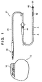
- Fig. 1 is a view showing the outer appearance of a pacemaker and an implantable electrode lead.
- an implantable electrode lead 21 has a flexible, predetermined-length lead body 20 having implantable electrodes 50 and 52 at its distal end and on its outer circumferential surface, respectively, and a connector 30 at the proximal end.
- the connector 30 is mechanically and electrically connected to a connector cavity 12 of a cardiac pacemaker 10 or an implantable defibrillator (not shown) to be detachable.
- the structure for electrical insulation and sealing of this mechanical and electrical connection is shown in Fig. 1, and a detailed description of this structure will be omitted.
- An endocardium fixing portion 60 is formed near the implantable electrode 50.
- the endocardium fixing portion 60 has a shaped portion (shown) which is to be hung from the trabeculae carneae or chordae tendineae in the heart chamber to fix the implantable electrode 50 to the endocardium immobile.
- a sleeve 40 is mounted on the outer surface of the lead body 20 to be movable along the longitudinal direction of the lead body 20.
- the sleeve 40 protects the lead body 20.
- the lead body 20 and the body tissue are fixed to each other by stitching the outer surface of the sleeve 40 together with the lead body 20.
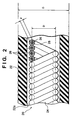
- the lead body 20 will be described with reference to Fig. 2 as a sectional view taken along the line of arrows A - A of Fig. 1.
- the lead body 20 preferably has an outer diameter G of 2 mm or less.
- An electrical conductive coil 24 of the lead body 20 preferably has an insulated multi-filar structure which is advantageous in coping with a multi-polar electrode wire and in realizing a small-diameter lead. A single-filar structure is also acceptable, as a matter of course.
- the total length of the implantable electrode lead 21 falls within a range of 400 mm to 600 mm. Therefore, after the conductive coil 24 is formed, the step of applying a sheath 22 on the sheath 22 is employed. During this step, a permanent forming strain sometimes remains between the conductive coil 24 and sheath 22. In order to reduce permanent forming strain residue, the difference in size between the outer circumferential surface of the conductive coil 24 and an inner-diameter portion 22a of the sheath 22 is preferably set to 50 ⁇ m (0.05 mm) or more.
- the difference (clearance) in size between the outer circumferential surface of the conductive coil 24 and the inner-diameter portion 22a of the sheath 22 is set to 50 ⁇ m or more in this manner, when a flexure load is applied to the lead body 20, the mutually acting forces of the sheath 22 and conductive coil 24 can be reduced, so that the service life of the lead body 20 against flexure can be prolonged.
- a conductive wire 26 constituting the electrical conductive coil 24 is formed with an insulating coating layer 28.
- the conductive wire 26 uses a composite structure constituted by a first metal material 26a, e.g., silver or copper, having a low electric resistivity, and a second metal material 26b, e.g., stainless steel or cobalt-based alloy, having excellent corrosion resistance and mechanical characteristics, the pacing energy can be economized.
- the electric resistivity of the first metal material 26a is preferably 5.0 ⁇ cm or less at room temperature of 20°C, and silver having an electric resistivity of 1.59 ⁇ cm at room temperature of 20°C is preferably used.
- DFT Dense Filled Tubing
- DBS Dense Brazed Strand
- a lead body 20 of Example 1 (T1) has an outer diameter G of 1.9 mm.
- the material of a sheath 22 is silicone having a Shore hardness of 70A.
- An electrical conductive coil 24 is formed of a multi-filar structure of four conductive coils 24 each formed with an insulating coating layer 28 made of a fluoroplastic.
- a spring index (D/d) as a ratio of the coil pitch diameter (mean diameter) (D) of the electrical conductive coil 24 to the diameter (d) of the conductive wire 26 is 9.0.
- the sectional area of the first metal material 26a occupies 25% the entire sectional area, and silver is used to form the first metal material 26a.
- the DFT wire (described above) formed of the cobalt-based alloy as the second metal material 26b is used.
- Example 2 (T2) is obtained by replacing the material of the sheath 22 of Example 1 (T1) with silicone having a Shore hardness of 55A.
- Example 3 (T3) is obtained by changing the spring index of the electrical conductive coil 24 of Example 1 (T1) to 10.0.
- Comparative Example 1 (S1) is obtained by changing the spring index of the electrical conductive coil 24 of Example 1 (T1) to 6.3.
- Comparative Example 2 (S2) is obtained by changing the spring index of the electrical conductive coil 24 of Example 1 (T1) to 7.8.
- Comparative Example 3 is obtained by replacing the material of the sheath 22 of Example 1 (T1) with silicone having a Shore hardness of 80A.
- Comparative Example 4 Comparative Example 4 (S4), the material of the sheath 22 of Example 1 is replaced with polyurethane having a Shore hardness of 55D.
- the outer diameter of a lead body 20 is 1.5 mm.
- An electrical conductive coil 24 is constituted by two conductive wires 26 each formed with an insulating coating layer 28 made of a fluoroplastic.
- the spring index (D/d) of the electrical conductive coil 24 and conductive wires 26 is 6.36.
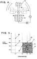
- Examples 1 to 3 and Comparative Examples 1 to 4 are plotted in the graph defined by the hardness and spring index.
- the hatched portion in Fig. 5 includes Examples 1 to 3 described above.
- a lead body 20 constituted by a combination in this hatched region exhibited good flexure durability.
- Fig. 6 shows the number of times of flexure and the number of fractured conductive coils.
- the sheath 22 is made of a comparatively soft material, since the conductive coil 24 has a small spring index, the torsion stress of the conductive wire 26 becomes excessive, and the conductive wire 26 was disconnected at a comparatively early time.
- the present invention includes any arrangements that can be selected in order to obtain substantially the same effect as that described in this specification, as a matter of course.
- an implantable electrode lead in which durability against the pressure applied under the clavicle, repeated flexure caused in the body tissue, or flexure with a very small radius of curvature is improved, and the lead body has softness, so that the mechanical stress applied by the lead body on the body tissue can be reduced.
Landscapes
- Health & Medical Sciences (AREA)
- Cardiology (AREA)
- Heart & Thoracic Surgery (AREA)
- Engineering & Computer Science (AREA)
- Biomedical Technology (AREA)
- Nuclear Medicine, Radiotherapy & Molecular Imaging (AREA)
- Radiology & Medical Imaging (AREA)
- Life Sciences & Earth Sciences (AREA)
- Animal Behavior & Ethology (AREA)
- General Health & Medical Sciences (AREA)
- Public Health (AREA)
- Veterinary Medicine (AREA)
- Electrotherapy Devices (AREA)
Applications Claiming Priority (3)
| Application Number | Priority Date | Filing Date | Title |
|---|---|---|---|
| JP10146279A JPH11333000A (ja) | 1998-05-27 | 1998-05-27 | 生体植設用電極リード |
| JP14627998 | 1998-05-27 | ||
| PCT/JP1999/002762 WO1999061098A1 (en) | 1998-05-27 | 1999-05-26 | Implantable electrode lead |
Publications (2)
| Publication Number | Publication Date |
|---|---|
| EP1005879A1 true EP1005879A1 (de) | 2000-06-07 |
| EP1005879A4 EP1005879A4 (de) | 2008-11-26 |
Family
ID=15404136
Family Applications (1)
| Application Number | Title | Priority Date | Filing Date |
|---|---|---|---|
| EP99922490A Withdrawn EP1005879A4 (de) | 1998-05-27 | 1999-05-26 | Implantierbare elektrodenleitung |
Country Status (4)
| Country | Link |
|---|---|
| US (1) | US6289250B1 (de) |
| EP (1) | EP1005879A4 (de) |
| JP (1) | JPH11333000A (de) |
| WO (1) | WO1999061098A1 (de) |
Cited By (4)
| Publication number | Priority date | Publication date | Assignee | Title |
|---|---|---|---|---|
| WO2004030751A1 (en) * | 2002-09-30 | 2004-04-15 | Medtronic, Inc. | Implantable medical device lead conductor and process for forming |
| US6950710B2 (en) | 2000-03-06 | 2005-09-27 | Terumo Kabushiki Kaisha | Implantable electrode lead and implantable medical instrument using the implantable electrode lead |
| WO2013071120A1 (en) * | 2011-11-11 | 2013-05-16 | Advanced Neuromodulation Systems, Inc. | Stimulation lead and method of fabrication |
| EP4364789A4 (de) * | 2021-06-23 | 2025-03-19 | Jiangsu Ced Medtech Co., Ltd | System zur peripheren nervenstimulation |
Families Citing this family (49)
| Publication number | Priority date | Publication date | Assignee | Title |
|---|---|---|---|---|
| JP2001029480A (ja) | 1999-07-23 | 2001-02-06 | Terumo Corp | 生体植設用電極リード |
| US7783365B2 (en) * | 2002-04-11 | 2010-08-24 | Medtronic, Inc. | Implantable medical device conductor insulation and process for forming |
| US8396568B2 (en) * | 2002-04-11 | 2013-03-12 | Medtronic, Inc. | Medical electrical lead body designs incorporating energy dissipating shunt |
| US20030216800A1 (en) * | 2002-04-11 | 2003-11-20 | Medtronic, Inc. | Implantable medical device conductor insulation and process for forming |
| US7904178B2 (en) * | 2002-04-11 | 2011-03-08 | Medtronic, Inc. | Medical electrical lead body designs incorporating energy dissipating shunt |
| EP1581102A4 (de) | 2002-12-11 | 2006-12-20 | Proteus Biomedical Inc | Verfahren und system zur überwachung und behandlung von hämodynamischen parametern |
| US8103358B2 (en) * | 2003-04-04 | 2012-01-24 | Medtronic, Inc. | Mapping guidelet |
| US20040215299A1 (en) * | 2003-04-23 | 2004-10-28 | Medtronic, Inc. | Implantable medical device conductor insulation and process for forming |
| US7214189B2 (en) * | 2004-09-02 | 2007-05-08 | Proteus Biomedical, Inc. | Methods and apparatus for tissue activation and monitoring |
| US20060161211A1 (en) * | 2004-12-31 | 2006-07-20 | Todd Thompson | Implantable accelerometer-based cardiac wall position detector |
| US9901731B2 (en) * | 2006-01-31 | 2018-02-27 | Medtronic, Inc. | Medical electrical lead having improved inductance |
| US20070179582A1 (en) * | 2006-01-31 | 2007-08-02 | Marshall Mark T | Polymer reinforced coil conductor for torque transmission |
| US7610101B2 (en) * | 2006-11-30 | 2009-10-27 | Cardiac Pacemakers, Inc. | RF rejecting lead |
| CN101636837B (zh) * | 2007-03-23 | 2011-07-27 | 富士通株式会社 | 电子装置、安装有电子装置的电子设备、安装有电子装置的物品、电子装置的制造方法 |
| AU2008335462B2 (en) | 2007-12-06 | 2014-02-20 | Cardiac Pacemakers, Inc. | Implantable lead having a variable coil conductor pitch |
| WO2009100003A1 (en) | 2008-02-06 | 2009-08-13 | Cardiac Pacemakers, Inc. | Lead with mri compatible design features |
| WO2009131749A2 (en) | 2008-02-28 | 2009-10-29 | Proteus Biomedical, Inc. | Integrated circuit implementation and fault control system, device, and method |
| US8600518B2 (en) * | 2008-04-30 | 2013-12-03 | Boston Scientific Neuromodulation Corporation | Electrodes for stimulation leads and methods of manufacture and use |
| US8103360B2 (en) | 2008-05-09 | 2012-01-24 | Foster Arthur J | Medical lead coil conductor with spacer element |
| US20090287266A1 (en) * | 2008-05-13 | 2009-11-19 | Mark Zdeblick | High-voltage tolerant multiplex multi-electrode stimulation systems and methods for using the same |
| US20110004286A1 (en) * | 2009-01-02 | 2011-01-06 | Medtronic, Inc. | System and method for cardiac lead |
| US9833616B2 (en) * | 2009-01-02 | 2017-12-05 | Medtronic, Inc. | System and method for cardiac lead |
| US9084883B2 (en) * | 2009-03-12 | 2015-07-21 | Cardiac Pacemakers, Inc. | Thin profile conductor assembly for medical device leads |
| US8478423B2 (en) * | 2009-04-07 | 2013-07-02 | Boston Scientific Neuromodulation Corporation | Insulator layers for leads of implantable electric stimulation systems and methods of making and using |
| JP2010257687A (ja) * | 2009-04-23 | 2010-11-11 | Junkosha Co Ltd | コイル状電線 |
| JP2012525206A (ja) | 2009-04-29 | 2012-10-22 | プロテウス バイオメディカル インコーポレイテッド | 移植可能なデバイスのためのリード線のための方法および装置 |
| WO2010151376A1 (en) | 2009-06-26 | 2010-12-29 | Cardiac Pacemakers, Inc. | Medical device lead including a unifilar coil with improved torque transmission capacity and reduced mri heating |
| US8406896B2 (en) * | 2009-06-29 | 2013-03-26 | Boston Scientific Neuromodulation Corporation | Multi-element contact assemblies for electrical stimulation systems and systems and methods of making and using |
| JP5730872B2 (ja) | 2009-07-23 | 2015-06-10 | プロテウス デジタル ヘルス, インコーポレイテッド | 固体薄膜コンデンサ |
| US8335572B2 (en) * | 2009-10-08 | 2012-12-18 | Cardiac Pacemakers, Inc. | Medical device lead including a flared conductive coil |
| US9254380B2 (en) | 2009-10-19 | 2016-02-09 | Cardiac Pacemakers, Inc. | MRI compatible tachycardia lead |
| AU2010337309B2 (en) * | 2009-12-30 | 2014-01-23 | Cardiac Pacemakers, Inc. | MRI-conditionally safe medical device lead |
| US8391994B2 (en) | 2009-12-31 | 2013-03-05 | Cardiac Pacemakers, Inc. | MRI conditionally safe lead with low-profile multi-layer conductor for longitudinal expansion |
| US8798767B2 (en) * | 2009-12-31 | 2014-08-05 | Cardiac Pacemakers, Inc. | MRI conditionally safe lead with multi-layer conductor |
| US9216257B2 (en) * | 2010-03-25 | 2015-12-22 | Medtronic, Inc. | Method and apparatus for guiding an external needle to an implantable device |
| US8475407B2 (en) | 2010-03-25 | 2013-07-02 | Medtronic, Inc. | Method and apparatus for guiding an external needle to an implantable device |
| US8483802B2 (en) | 2010-03-25 | 2013-07-09 | Medtronic, Inc. | Method and apparatus for guiding an external needle to an implantable device |
| US9339601B2 (en) * | 2010-03-25 | 2016-05-17 | Medtronic, Inc. | Method and apparatus for guiding an external needle to an implantable device |
| US8825181B2 (en) | 2010-08-30 | 2014-09-02 | Cardiac Pacemakers, Inc. | Lead conductor with pitch and torque control for MRI conditionally safe use |
| AU2012333113B2 (en) | 2011-11-04 | 2014-11-20 | Cardiac Pacemakers, Inc. | Implantable medical device lead including inner coil reverse-wound relative to shocking coil |
| JP5905611B2 (ja) | 2012-04-20 | 2016-04-20 | カーディアック ペースメイカーズ, インコーポレイテッド | ユニファイラーコイル状ケーブルを備える埋込型医療装置リード |
| JP2013232356A (ja) | 2012-04-27 | 2013-11-14 | Junkosha Co Ltd | コイル状ケーブル |
| US8954168B2 (en) | 2012-06-01 | 2015-02-10 | Cardiac Pacemakers, Inc. | Implantable device lead including a distal electrode assembly with a coiled component |
| US8958889B2 (en) | 2012-08-31 | 2015-02-17 | Cardiac Pacemakers, Inc. | MRI compatible lead coil |
| EP2908903B1 (de) | 2012-10-18 | 2016-08-31 | Cardiac Pacemakers, Inc. | Induktives element für mri-kompatibilität in einer leitung eines implantierbaren medizinproduktes |
| US10575743B2 (en) | 2013-04-11 | 2020-03-03 | Biosense Webster (Israel) Ltd. | High electrode density basket catheter |
| US10602947B2 (en) | 2013-04-11 | 2020-03-31 | Biosense Webster (Israel), Ltd. | High density electrode structure |
| WO2015130753A1 (en) | 2014-02-26 | 2015-09-03 | Cardiac Pacemakers, Inc | Construction of an mri-safe tachycardia lead |
| EP3675950B1 (de) | 2017-08-29 | 2023-10-11 | Medtronic, Inc. | Implantierbare medizinische elektrodenleitung, zugehöriges montageverfahren und implantatsystem |
Family Cites Families (9)
| Publication number | Priority date | Publication date | Assignee | Title |
|---|---|---|---|---|
| FR2463625A1 (fr) * | 1979-08-23 | 1981-02-27 | Medtronic Inc | Conducteur multipolaire pour stimulateur cardiaque |
| DE8211625U1 (de) * | 1982-04-22 | 1985-09-12 | Siemens AG, 1000 Berlin und 8000 München | Mehrpolige elektrische Leitung |
| JPS58192206U (ja) | 1982-06-17 | 1983-12-21 | 大日本印刷株式会社 | 電子線による包材殺菌装置のチヤンバ−構造 |
| CH662669A5 (de) * | 1984-04-09 | 1987-10-15 | Straumann Inst Ag | Leitvorrichtung zum mindestens teilweisen einsetzen in einen menschlichen oder tierischen koerper, mit einer zumindest aus einem leiter gebildeten wendel. |
| US4643202A (en) * | 1985-04-15 | 1987-02-17 | Cordis Corporation | Multi-material insulation sheath for pacer lead |
| EP0293499B1 (de) * | 1987-06-01 | 1993-09-01 | Siemens-Elema AB | Implantierbare vielpolige koaxiale Leitung |
| US5318572A (en) * | 1992-06-02 | 1994-06-07 | Siemens Pacesetter, Inc. | High efficiency tissue stimulating and signal sensing electrode |
| US5483022A (en) * | 1994-04-12 | 1996-01-09 | Ventritex, Inc. | Implantable conductor coil formed from cabled composite wire |
| US5796044A (en) * | 1997-02-10 | 1998-08-18 | Medtronic, Inc. | Coiled wire conductor insulation for biomedical lead |
-
1998
- 1998-05-27 JP JP10146279A patent/JPH11333000A/ja active Pending
-
1999
- 1999-05-26 US US09/380,464 patent/US6289250B1/en not_active Expired - Fee Related
- 1999-05-26 EP EP99922490A patent/EP1005879A4/de not_active Withdrawn
- 1999-05-26 WO PCT/JP1999/002762 patent/WO1999061098A1/ja not_active Ceased
Cited By (5)
| Publication number | Priority date | Publication date | Assignee | Title |
|---|---|---|---|---|
| US6950710B2 (en) | 2000-03-06 | 2005-09-27 | Terumo Kabushiki Kaisha | Implantable electrode lead and implantable medical instrument using the implantable electrode lead |
| WO2004030751A1 (en) * | 2002-09-30 | 2004-04-15 | Medtronic, Inc. | Implantable medical device lead conductor and process for forming |
| EP2044972A1 (de) * | 2002-09-30 | 2009-04-08 | Medtronic, Inc. | Führungsdraht einer implantierbaren medizinischen Vorrichtung |
| WO2013071120A1 (en) * | 2011-11-11 | 2013-05-16 | Advanced Neuromodulation Systems, Inc. | Stimulation lead and method of fabrication |
| EP4364789A4 (de) * | 2021-06-23 | 2025-03-19 | Jiangsu Ced Medtech Co., Ltd | System zur peripheren nervenstimulation |
Also Published As
| Publication number | Publication date |
|---|---|
| JPH11333000A (ja) | 1999-12-07 |
| WO1999061098A1 (en) | 1999-12-02 |
| US6289250B1 (en) | 2001-09-11 |
| EP1005879A4 (de) | 2008-11-26 |
Similar Documents
| Publication | Publication Date | Title |
|---|---|---|
| US6289250B1 (en) | Implantable electrode lead | |
| US5796044A (en) | Coiled wire conductor insulation for biomedical lead | |
| US5366496A (en) | Subcutaneous shunted coil electrode | |
| US4458695A (en) | Multipolar electrode assembly for pacing lead | |
| US4469104A (en) | Multipolar connector for pacing lead | |
| US5676694A (en) | Medical electrical lead | |
| JP4452724B2 (ja) | 延伸させたストランド充填管ワイヤ | |
| US4592372A (en) | Pacing/sensing electrode sleeve and method of forming same | |
| US6400992B1 (en) | Co-extruded, multi-lumen medical lead | |
| US6925334B1 (en) | Implantable medical lead having multiple, jointly insulated electrical conductors | |
| US6456888B1 (en) | Geometry for coupling and electrode to a conductor | |
| US5324328A (en) | Conductor for a defibrillator patch lead | |
| US9901731B2 (en) | Medical electrical lead having improved inductance | |
| US8554341B2 (en) | Implantable medical lead having passive lock mechanical body terminations | |
| US5928277A (en) | One piece defibrillation lead circuit | |
| JP5537213B2 (ja) | 電気刺激電極組立体 | |
| US8055353B2 (en) | Medical carriers comprising a low-impedance conductor, and methods of making and using the same | |
| US6253111B1 (en) | Multi-conductor lead | |
| EP3156100B1 (de) | Mrt-kompatible leiterspule | |
| JP2001511407A (ja) | 内径を最小化したスリーブをもつ心臓リード | |
| US6580949B1 (en) | Implantable electrode lead | |
| US20060293737A1 (en) | Multiple electrode implantable lead | |
| US20040249430A1 (en) | Implantable medical electrical lead | |
| US20020183824A1 (en) | Co-extruded, multi-lumen medical lead | |
| CN104870051B (zh) | 可植入医疗电引线导体和构造方法 |
Legal Events
| Date | Code | Title | Description |
|---|---|---|---|
| PUAI | Public reference made under article 153(3) epc to a published international application that has entered the european phase |
Free format text: ORIGINAL CODE: 0009012 |
|
| 17P | Request for examination filed |
Effective date: 20000224 |
|
| AK | Designated contracting states |
Kind code of ref document: A1 Designated state(s): BE DE FR GB IT NL SE |
|
| A4 | Supplementary search report drawn up and despatched |
Effective date: 20081024 |
|
| RIC1 | Information provided on ipc code assigned before grant |
Ipc: A61N 1/05 20060101AFI19991203BHEP |
|
| STAA | Information on the status of an ep patent application or granted ep patent |
Free format text: STATUS: THE APPLICATION IS DEEMED TO BE WITHDRAWN |
|
| 18D | Application deemed to be withdrawn |
Effective date: 20090122 |