EP1005897A2 - Dispositif pour la gazéification de boissons - Google Patents
Dispositif pour la gazéification de boissons Download PDFInfo
- Publication number
- EP1005897A2 EP1005897A2 EP99123499A EP99123499A EP1005897A2 EP 1005897 A2 EP1005897 A2 EP 1005897A2 EP 99123499 A EP99123499 A EP 99123499A EP 99123499 A EP99123499 A EP 99123499A EP 1005897 A2 EP1005897 A2 EP 1005897A2
- Authority
- EP
- European Patent Office
- Prior art keywords
- bottle
- nozzle tube
- carbon dioxide
- pressing device
- seal
- Prior art date
- Legal status (The legal status is an assumption and is not a legal conclusion. Google has not performed a legal analysis and makes no representation as to the accuracy of the status listed.)
- Withdrawn
Links
Images

Classifications
-
- A—HUMAN NECESSITIES
- A23—FOODS OR FOODSTUFFS; TREATMENT THEREOF, NOT COVERED BY OTHER CLASSES
- A23L—FOODS, FOODSTUFFS OR NON-ALCOHOLIC BEVERAGES, NOT OTHERWISE PROVIDED FOR; PREPARATION OR TREATMENT THEREOF
- A23L2/00—Non-alcoholic beverages; Dry compositions or concentrates therefor; Preparation or treatment thereof
- A23L2/52—Adding ingredients
- A23L2/54—Mixing with gases
-
- B—PERFORMING OPERATIONS; TRANSPORTING
- B01—PHYSICAL OR CHEMICAL PROCESSES OR APPARATUS IN GENERAL
- B01F—MIXING, e.g. DISSOLVING, EMULSIFYING OR DISPERSING
- B01F23/00—Mixing according to the phases to be mixed, e.g. dispersing or emulsifying
- B01F23/20—Mixing gases with liquids
- B01F23/23—Mixing gases with liquids by introducing gases into liquid media, e.g. for producing aerated liquids
- B01F23/236—Mixing gases with liquids by introducing gases into liquid media, e.g. for producing aerated liquids specially adapted for aerating or carbonating beverages
- B01F23/2361—Mixing gases with liquids by introducing gases into liquid media, e.g. for producing aerated liquids specially adapted for aerating or carbonating beverages within small containers, e.g. within bottles
-
- B—PERFORMING OPERATIONS; TRANSPORTING
- B01—PHYSICAL OR CHEMICAL PROCESSES OR APPARATUS IN GENERAL
- B01F—MIXING, e.g. DISSOLVING, EMULSIFYING OR DISPERSING
- B01F23/00—Mixing according to the phases to be mixed, e.g. dispersing or emulsifying
- B01F23/20—Mixing gases with liquids
- B01F23/23—Mixing gases with liquids by introducing gases into liquid media, e.g. for producing aerated liquids
- B01F23/237—Mixing gases with liquids by introducing gases into liquid media, e.g. for producing aerated liquids characterised by the physical or chemical properties of gases or vapours introduced in the liquid media
- B01F23/2376—Mixing gases with liquids by introducing gases into liquid media, e.g. for producing aerated liquids characterised by the physical or chemical properties of gases or vapours introduced in the liquid media characterised by the gas being introduced
- B01F23/23762—Carbon dioxide
-
- B—PERFORMING OPERATIONS; TRANSPORTING
- B01—PHYSICAL OR CHEMICAL PROCESSES OR APPARATUS IN GENERAL
- B01F—MIXING, e.g. DISSOLVING, EMULSIFYING OR DISPERSING
- B01F33/00—Other mixers; Mixing plants; Combinations of mixers
- B01F33/50—Movable or transportable mixing devices or plants
- B01F33/501—Movable mixing devices, i.e. readily shifted or displaced from one place to another, e.g. portable during use
- B01F33/5014—Movable mixing devices, i.e. readily shifted or displaced from one place to another, e.g. portable during use movable by human force, e.g. kitchen or table devices
Definitions
- the present invention relates to a device for carbonizing in Bottled drinks, with a housing which has a bottle compartment has a carbon dioxide storage container, which is attached to a manually operated metering valve can be connected, one to the metering valve connected nozzle tube and a connection device, which is a closure piece with a seal that seals against the bottle mouth is pressed, the nozzle tube through the closure in the inside of the bottle is sealed.
- Such devices enjoy compact household appliances Production of refreshingly sparkling, carbonated drinks at the End users growing in popularity. They allow on simple Add soda water from ordinary water, i.e. tap water prepare, as well as juices, mixed drinks or any other liquids to bottle with carbon dioxide, which is in small pressure bottles is available.
- the mode of operation is the same as that known from the prior art Devices essentially the same:
- the carbonated The drink is poured into a bottle. This becomes upright coupled gas-tight to the connection device, which is usually a filling nozzle arranged at the top of the bottle compartment.
- the connection device which is usually a filling nozzle arranged at the top of the bottle compartment.
- the metering valve is operated by hand, the Carbon dioxide is applied to the inside of the bottle through the nozzle tube. After detaching the bottle from the connection device and the Removal from the bottle compartment is the one contained in the bottle now carbonated drink ready for consumption.
- connection device for the bottle a screw-in thread or a bayonet connection in which the bottle with its bottle thread or with bayonet cams molded onto the bottle neck Connector is lockable.
- This connection has the advantage that the bottle is tight and close to the connecting piece.
- the insertion of one filled beverage bottle in this device is however relatively inconvenient since the bottle is first passed from below over the nozzle tube and must then be locked with a rotary movement.
- a One-hand operation is possible, especially for people with smaller ones Hands, practically hardly feasible. The same applies to operation with wet hands, like this when filling the bottle with Tap water is often inevitable.
- connection device sees it as being pressurizable against the bottle mouth Connection piece before, its seal sealing against the bottle mouth is pressed. Through the protruding from the connector However, the insertion of a filled bottle is also relative here laborious.
- the task arises the invention, a device of the type mentioned To provide a more convenient and easy handling, in particular enables one-handed operation and at the same time better quality the carbonization brings than the known devices.
- the invention proposes starting from the beginning mentioned prior art that the nozzle tube in the closure piece is mounted in a longitudinally displaceable manner that the connection device is a manually operable, force-increasing pressure device with an actuating element which, when actuated, the seal with increased actuation force presses against the bottle mouth and in this sealing position is self-sustaining.
- a special feature of the invention is that the nozzle tube in the closure piece and is thus longitudinally displaceable relative to the seal, d. that is the nozzle tube with respect to the portion that comes out of the sealing plane protrudes into the bottle interior, is retractable and extendable.
- the invention is characterized by a hand-operated pressing device out.
- This has an actuating element, for example one Operating lever with handle that can be swiveled by hand.
- This actuator is connected to a power-boosting transmission which on the output side has the seal with its power transmission ratio increased actuation force against the bottle mouth presses.
- a special feature of the drive mechanism is that in its end position, d. H. in the sealing position with sealing on the bottle mouth pressed-on seal a stable, self-holding position is taken. This means that the contact pressure via the pressure device into the housing is directed, so not against the direction of actuation on the actuator reacts. It is therefore fixed in the sealing position without additional locking or locking elements, so that no actuation such devices is required.
- a Eccentric be provided, which is rotated beyond its dead center and there has a stop so that it has a stable position in the pressing position.
- the immersion depth of the nozzle tube significant influence on the quality of carbonization, d. H. the Saturation and the desired fineness of the carbonated beverage, for example soda water.
- the immersion depth is independent of it definable.
- the features of the invention thus make it special for the first time Comfortable, real one-hand operation enables, at the same time a high Beverage quality, for example of soda water, is guaranteed.
- the closure piece is expediently from above against the bottle mouth lowered and attached to the pressing device.
- the pressure device preferably has a self-locking power transmission. This ensures that pressure forces exerted on the seal are not directly on the actuating element act back.
- Eccentric gear design in which the actuating element with a Eccentric disc is connected. This acts with its eccentric surface of on top of the closure piece and preferably has a stop surface, so that they shortly after passing the dead center in the pressure position (Sealing position) assumes a stable position.
- This version has the The advantage of being easy to manufacture and extremely reliable.
- a lever mechanism with toggle levers or the like to provide.
- the seal is advantageously as a flat seal made of elastic Material, preferably resilient plastic or the like is formed.
- This design has the advantage that, on the one hand, no radial forces be exercised on the bottle mouth and on the other in A safety pressure relief valve works together with the bottle mouth is formed, which automatically blows off when there is excess pressure in the bottle. Due to the hardness, H. the flexibility of the plastic Tolerances in bottle height compensated.
- the operating element of the pressing device interacts with a shut-off valve, which is in the carbon dioxide line is in front of the metering valve, and this check valve in the sealing position of the pressing device opens.
- a shut-off valve which is in the carbon dioxide line is in front of the metering valve, and this check valve in the sealing position of the pressing device opens.
- the sliding nozzle tube is preferably operated via a handling element attached to the upper end of the nozzle tube, for example a push button or the like which is well suited for one-hand operation. If this handling element is pressed down, it will Lowered the nozzle tube into the bottle. The fact that the handling element is spring-loaded in the retracted position of the nozzle tube, the nozzle tube moves after releasing the handling element automatically returns to the retracted starting position.
- a handling element attached to the upper end of the nozzle tube, for example a push button or the like which is well suited for one-hand operation. If this handling element is pressed down, it will Lowered the nozzle tube into the bottle.
- the fact that the handling element is spring-loaded in the retracted position of the nozzle tube, the nozzle tube moves after releasing the handling element automatically returns to the retracted starting position.
- the arrangement explained above is particularly user-friendly characterized in that the handling element with the actuator of Dosing valve is connected.
- the handling element with the actuator of Dosing valve is connected.
- depressing the handling element is thus when a predetermined immersion depth of the nozzle tube is reached automatically triggered the carbon dioxide release into the beverage bottle.
- the sequence the functional steps are thus firmly defined.
- Nozzle tube is telescopically extendable.
- it is thereby as a piston of a piston-cylinder unit to which carbon dioxide can be applied educated.
- This piston-cylinder unit is via the metering valve connected to the carbon dioxide pressure bottle.
- the cylinder barrel of this Piston-cylinder unit can, for example, be perpendicular to the top Closure piece may be attached. If the metering valve becomes When a beverage is carbonated, the piston-cylinder unit is opened first pressurized so that the nozzle tube telescopically into the The inside of the bottle is extended. It becomes practical semi-automatic operation realized. It is not an additional one mechanical manual operation when lowering the nozzle tube more required.
- the nozzle tube is created by the pressure built up in the beverage bottle automatically pushed back into the starting position. Possibly a weak spring can be arranged in the piston-cylinder unit, to help retract the nozzle tube. So it will Nozzle tube practical at the end of the carbonation process automatically retracted so that the bottle is easy to remove.
- the carbon dioxide pressure vessel is used for household appliances preferably included in the housing, which is a compact floor-standing housing is trained.
- the bottle compartment are - preferably on the back - guide rails appropriate. These make it easier to insert a beverage bottle.
- Nozzle heads with nozzles that shift in number, dimensions and shape can be configured, it is possible to influence the carbonization. According to the wishes of the users, it is conceivable, interchangeable Nozzle heads for different degrees of saturation or the pearliness of the to provide carbonated drink.
- the device according to the invention with additional Provide safety valves. These prevent the build-up of harmful ones Carbon dioxide overpressure in the device and should be designed redundantly several times his.
- the device according to the invention are electromechanical, hydraulic and / or pneumatic actuators arranged to actuate the pressing device and / or the Nozzle pipe.
- the ones that can be operated directly manually in the basic version Functions can now be performed using the motor elements mentioned indirectly operated, that is to be controlled remotely. This results in the Possibility of indirect manual control, or the Integration of the device according to the invention in a vending machine, which, for example to control the operating sequence with an electrical Control is provided.
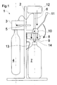
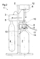
- FIG. 1 to 3 show a device for carbonization according to the invention of drinks, schematically with the outer panel removed is shown and is provided as a whole with the reference number 1.
- the device 1 has a housing 2, which consists of the frame-like carrier together with that not shown here External cladding is formed and all functional components in itself records.
- Dosing valve 3 which also serves as a connection fitting for a carbon dioxide pressure bottle 4 is formed.
- the metering valve 3 has a release lever 5.
- a nozzle tube 6 is connected to the metering valve 3.
- a closure piece 8 which is slidable in the direction of the double arrow is mounted on the housing 2 and a on its underside against the bottle mouth flat gasket 9 made of resilient Identifies plastic.
- This closure piece 8 forms together with the Eccentric 10, which is rotatably mounted on the housing 2 and a hand lever 11 has, the pressing device according to the invention. Their function is in following explained.
- the nozzle tube 6 mentioned above is vertical, longitudinally displaceable through the closure piece 8 and the seal 9 passed and at the top Provide an operating button 12 at the end.
- the nozzle tube 6 can be moved down, like this is shown with the dashed arrow.
- the device 1 functions as follows: First the beverage bottle 7 is filled with beverage, which is carbonated to be moved and as shown in Fig. 1 in the receiving compartment below put the seal 9. This is simple and by the guide rails 13 Can be carried out conveniently with one hand. Then the hand lever 11 - with the same hand - folded down in the direction of the curved arrow, until the sealing position shown in Fig. 2 is reached. By pivoting the eccentric 10, the closure piece 8 is lowered down, so that the seal 9 is pressed sealingly onto the bottle mouth becomes.
- the nozzle head denoted by reference numeral 14 is interchangeable attached to the nozzle tube 6, for example screwed. So he can easily against such an execution with a different number, or smaller or larger nozzle openings can be replaced.
- the operating button 12 is first released, which is then due to the excess pressure in the beverage bottle 7 and optionally by means of a spring (not shown here) in the starting position, as shown in Figs. 1 and 2, is pushed back. Subsequently with the same hand the hand lever 11 in the starting position Fig. 1 moved back. The seal 9 is from the bottle mouth lifted off so that excess carbon dioxide from the beverage bottle 7 is blown off safely. After the starting position shown in Fig. 1 is reached again, the beverage bottle 7 with the now finished, fresh fizzy drink removed from the device 1 and is now ready for consumption.
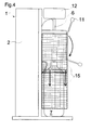
- Fig. 4 shows a clad version of that shown in Figs. 1 to 3 Contraption.
- the reference numeral 15 designates a security basket therein, which is displaceable in the direction of the solid arrows on the housing 2 is stored.
- This safety cage 15 is with the hand lever 11 connected.
- the closing of the burst protection device realized thereby is therefore carried out automatically without the need for any further manipulation would.
- the operation of the device 1 according to the invention is therefore complete Can be carried out conveniently with one hand. Operation is easier and safer than in the prior art, whereby according to the invention movable nozzle tube 6 an optimal immersion depth and thus optimal Carbonization conditions can be specified.
- the exchangeable nozzle head 14 allows the device 1 to be used in a wide variety of ways Carbonization needs are matched.
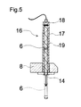
- FIG. 6 An alternative embodiment of a nozzle tube 6 is shown in FIG.
- the special thing is that the nozzle tube 6 as a piston Piston-cylinder unit 16 is formed.
- the cylinder tube 17 is, for example attached to the top of the closure piece 8 according to Figures 1 to 4, so that the nozzle tube 6 telescopically down into the bottle interior is extendable, as indicated by the arrow in this illustration.
- the cylinder tube 17 is in the embodiment shown at the rear, that is at the top of the carbon dioxide line coming from the metering valve 3 connected.
- the piston-cylinder unit 16 When carbonizing, the piston-cylinder unit 16 is with Carbon dioxide is applied so that the nozzle tube 6 is pressurized below, that is, extends into the inside of the bottle.
- the End stop carbon dioxide flows through the passage opening 18 and the nozzle head 14 into the inside of the bottle and ensures carbonation of the drink.
Landscapes
- Chemical & Material Sciences (AREA)
- Chemical Kinetics & Catalysis (AREA)
- Health & Medical Sciences (AREA)
- Nutrition Science (AREA)
- Life Sciences & Earth Sciences (AREA)
- Engineering & Computer Science (AREA)
- Food Science & Technology (AREA)
- Polymers & Plastics (AREA)
- Devices For Dispensing Beverages (AREA)
- Closures For Containers (AREA)
Applications Claiming Priority (2)
| Application Number | Priority Date | Filing Date | Title |
|---|---|---|---|
| DE19855170 | 1998-11-30 | ||
| DE19855170A DE19855170A1 (de) | 1998-11-30 | 1998-11-30 | Vorrichtung zur Karbonisierung von Getränken |
Publications (2)
| Publication Number | Publication Date |
|---|---|
| EP1005897A2 true EP1005897A2 (fr) | 2000-06-07 |
| EP1005897A3 EP1005897A3 (fr) | 2002-07-10 |
Family
ID=7889483
Family Applications (1)
| Application Number | Title | Priority Date | Filing Date |
|---|---|---|---|
| EP99123499A Withdrawn EP1005897A3 (fr) | 1998-11-30 | 1999-11-25 | Dispositif pour la gazéification de boissons |
Country Status (2)
| Country | Link |
|---|---|
| EP (1) | EP1005897A3 (fr) |
| DE (1) | DE19855170A1 (fr) |
Cited By (9)
| Publication number | Priority date | Publication date | Assignee | Title |
|---|---|---|---|---|
| EP1607664A1 (fr) * | 2004-06-16 | 2005-12-21 | Daewoo Electronics Corporation | Dispositif d'actionnement de soupape |
| EP1905504A1 (fr) * | 2006-09-26 | 2008-04-02 | Kuei-Tang Chang | Dispositif d'alimentation en gaz pour machine à boissons gazeuses |
| US7975988B2 (en) | 2004-09-29 | 2011-07-12 | Soda-Club Ltd. | Device for carbonating a liquid with pressurized gas |
| CN102188162A (zh) * | 2010-03-14 | 2011-09-21 | 苏打斯特里姆工业有限公司 | 家用苏打机的气体计量设备 |
| CN105371581A (zh) * | 2014-08-13 | 2016-03-02 | 三星电子株式会社 | 冰箱及其控制方法 |
| WO2021174306A1 (fr) * | 2020-03-05 | 2021-09-10 | Sodaking IPV Pty Ltd | Appareil de carbonatation de boisson à la demande |
| US12005408B1 (en) | 2023-04-14 | 2024-06-11 | Sharkninja Operating Llc | Mixing funnel |
| US12017192B1 (en) | 2023-06-16 | 2024-06-25 | Sharkninja Operating Llc | Carbonation mixing nozzles |
| US12268999B2 (en) | 2020-03-05 | 2025-04-08 | Sixteen Stone Operations Pty Ltd | Beverage carbonation apparatus |
Families Citing this family (4)
| Publication number | Priority date | Publication date | Assignee | Title |
|---|---|---|---|---|
| WO2001010247A1 (fr) * | 1999-08-04 | 2001-02-15 | Boluo Yaofeng Electronics Co. Ltd. | Tuyau de gonflage extensible |
| RU2598556C2 (ru) * | 2011-06-03 | 2016-09-27 | Бревилл Пти Лимитед | Газирующее устройство |
| CN102973147A (zh) * | 2011-09-05 | 2013-03-20 | 创意国际有限公司 | 一种苏打水机 |
| NL2020878B1 (nl) * | 2018-05-03 | 2019-11-12 | Quooker Int B V | Inrichting voor het afgeven van een koolzuurhoudende vloeistof |
Family Cites Families (7)
| Publication number | Priority date | Publication date | Assignee | Title |
|---|---|---|---|---|
| FR673920A (fr) * | 1928-04-26 | 1930-01-21 | Dispositif pour l'injection de fluides dans des récipients fermés par des bouchons | |
| US2628828A (en) * | 1948-08-27 | 1953-02-17 | Meurer Nicolaus | Portable aeration apparatus |
| US2723790A (en) * | 1950-04-05 | 1955-11-15 | Nat Dairy Res Lab Inc | Gas charging machine and method |
| SE8002181L (sv) * | 1980-03-20 | 1981-09-21 | Intercylinder Ab | Anordning for att kolsyresetta drycker |
| ZA812894B (en) * | 1980-05-13 | 1982-05-26 | Thorn Cascade Co Ltd | Appliance for making an aerated beverage and a cap for a bottle used therein |
| EP0935993A1 (fr) * | 1998-02-10 | 1999-08-18 | Kautz, Peter | Dispositif pour enrichir un liquide en gaz |
| TR199801497U (xx) * | 1998-08-03 | 2000-03-21 | Çağlar Şeref | Soda makinalarında yenilik. |
-
1998
- 1998-11-30 DE DE19855170A patent/DE19855170A1/de not_active Withdrawn
-
1999
- 1999-11-25 EP EP99123499A patent/EP1005897A3/fr not_active Withdrawn
Cited By (13)
| Publication number | Priority date | Publication date | Assignee | Title |
|---|---|---|---|---|
| EP1607664A1 (fr) * | 2004-06-16 | 2005-12-21 | Daewoo Electronics Corporation | Dispositif d'actionnement de soupape |
| US7975988B2 (en) | 2004-09-29 | 2011-07-12 | Soda-Club Ltd. | Device for carbonating a liquid with pressurized gas |
| EP1905504A1 (fr) * | 2006-09-26 | 2008-04-02 | Kuei-Tang Chang | Dispositif d'alimentation en gaz pour machine à boissons gazeuses |
| CN102188162A (zh) * | 2010-03-14 | 2011-09-21 | 苏打斯特里姆工业有限公司 | 家用苏打机的气体计量设备 |
| CN102188162B (zh) * | 2010-03-14 | 2014-11-05 | 苏打斯特里姆工业有限公司 | 家用苏打机的气体计量设备 |
| CN105371581B (zh) * | 2014-08-13 | 2018-10-19 | 三星电子株式会社 | 冰箱及其控制方法 |
| CN105371581A (zh) * | 2014-08-13 | 2016-03-02 | 三星电子株式会社 | 冰箱及其控制方法 |
| US10473385B2 (en) | 2014-08-13 | 2019-11-12 | Samsung Electronics Co., Ltd. | Refrigerator and controlling method thereof |
| WO2021174306A1 (fr) * | 2020-03-05 | 2021-09-10 | Sodaking IPV Pty Ltd | Appareil de carbonatation de boisson à la demande |
| US12268999B2 (en) | 2020-03-05 | 2025-04-08 | Sixteen Stone Operations Pty Ltd | Beverage carbonation apparatus |
| US12005408B1 (en) | 2023-04-14 | 2024-06-11 | Sharkninja Operating Llc | Mixing funnel |
| US12017192B1 (en) | 2023-06-16 | 2024-06-25 | Sharkninja Operating Llc | Carbonation mixing nozzles |
| US12533643B2 (en) | 2023-06-16 | 2026-01-27 | Sharkninja Operating Llc | Carbonation mixing nozzles |
Also Published As
| Publication number | Publication date |
|---|---|
| EP1005897A3 (fr) | 2002-07-10 |
| DE19855170A1 (de) | 2000-05-31 |
Similar Documents
| Publication | Publication Date | Title |
|---|---|---|
| EP3473587B1 (fr) | Dispositif et procédé de remplissage d'un récipient à remplir d'un produit de remplissage | |
| EP1005897A2 (fr) | Dispositif pour la gazéification de boissons | |
| DE3825093A1 (de) | Verfahren und vorrichtung zum fuellen von flaschen oder dergl. in gegendruckfuellmaschinen | |
| DE3210154A1 (de) | Umfuellvorrichtung zum umfuellen von fluessigkeiten, insbesondere fluessigem dauerwellmittel | |
| EP0528190A1 (fr) | Récipient sous pression à deux composants notamment pour mousse à deux composants | |
| EP0662069B1 (fr) | Dispositif de mise en perce pour cannelle d'un tonnelet | |
| EP0946273B1 (fr) | Dispositif de gazeification de liquide | |
| DE102005022446B3 (de) | Partyfass | |
| EP0867219B1 (fr) | Appareil permettant d'additioner du gaz carbonique à un liquide | |
| EP2014607A2 (fr) | Application de pression pour récipients contenant des boissons et procédé de fonctionnement correspondant | |
| EP2295372B1 (fr) | Chapiteau destiné à tirer par pression pour conteneur à bière et procédé de fonctionnement de celui-ci | |
| DE4121817C2 (fr) | ||
| DE9109177U1 (de) | Zapfkopf | |
| WO2024245875A1 (fr) | Dispositif d'introduction de gaz dans un récipient de liquide | |
| EP4539973A1 (fr) | Bouteille | |
| DE2736281A1 (de) | Armatur fuer einen drucktank | |
| EP0935993A1 (fr) | Dispositif pour enrichir un liquide en gaz | |
| DE8808536U1 (de) | Probeentnahmehahn als Absperrkugelhahn | |
| DE29622248U1 (de) | Karbonisiervorrichtung | |
| WO2004089807A2 (fr) | Tete distributrice destinee a etre installee sur un raccord monte sur une conduite montante de boisson | |
| DE29712912U1 (de) | Vorrichtung zum Karbonisieren mit einem von außen zugänglichen Bedienungselement | |
| DE20215897U1 (de) | Vorrichtung zum Filtern von Flüssigkeit und zum Lösen eines Gases in einer Flüssigkeit | |
| DE102009046727A1 (de) | Vorrichtung zum Schutz von Getränken | |
| DE2725466A1 (de) | Vorrichtung zum eintreiben eines stopfens in das zapfloch eines fasses | |
| EP0909580A2 (fr) | Dispositif et méthode pour l'introduction de gaz dans des liquides |
Legal Events
| Date | Code | Title | Description |
|---|---|---|---|
| PUAI | Public reference made under article 153(3) epc to a published international application that has entered the european phase |
Free format text: ORIGINAL CODE: 0009012 |
|
| AK | Designated contracting states |
Kind code of ref document: A2 Designated state(s): AT BE CH CY DE DK ES FI FR GB GR IE IT LI LU MC NL PT SE |
|
| AX | Request for extension of the european patent |
Free format text: AL;LT;LV;MK;RO;SI |
|
| PUAL | Search report despatched |
Free format text: ORIGINAL CODE: 0009013 |
|
| AK | Designated contracting states |
Kind code of ref document: A3 Designated state(s): AT BE CH CY DE DK ES FI FR GB GR IE IT LI LU MC NL PT SE |
|
| AX | Request for extension of the european patent |
Free format text: AL;LT;LV;MK;RO;SI |
|
| 19U | Interruption of proceedings before grant |
Effective date: 20020501 |
|
| 19W | Proceedings resumed before grant after interruption of proceedings |
Effective date: 20021217 |
|
| AKX | Designation fees paid |
Designated state(s): AT BE CH CY DE DK ES FI FR GB GR IE IT LI LU MC NL PT SE |
|
| STAA | Information on the status of an ep patent application or granted ep patent |
Free format text: STATUS: THE APPLICATION IS DEEMED TO BE WITHDRAWN |
|
| 18D | Application deemed to be withdrawn |
Effective date: 20030618 |