EP1005936A2 - Ausblas- und Ausspritzeinrichtung für Schnellspannzylinder mit Deckel - Google Patents
Ausblas- und Ausspritzeinrichtung für Schnellspannzylinder mit Deckel Download PDFInfo
- Publication number
- EP1005936A2 EP1005936A2 EP99117641A EP99117641A EP1005936A2 EP 1005936 A2 EP1005936 A2 EP 1005936A2 EP 99117641 A EP99117641 A EP 99117641A EP 99117641 A EP99117641 A EP 99117641A EP 1005936 A2 EP1005936 A2 EP 1005936A2
- Authority
- EP
- European Patent Office
- Prior art keywords
- blow
- compressed air
- cover
- bore
- quick
- Prior art date
- Legal status (The legal status is an assumption and is not a legal conclusion. Google has not performed a legal analysis and makes no representation as to the accuracy of the status listed.)
- Granted
Links
Images


Classifications
-
- B—PERFORMING OPERATIONS; TRANSPORTING
- B23—MACHINE TOOLS; METAL-WORKING NOT OTHERWISE PROVIDED FOR
- B23H—WORKING OF METAL BY THE ACTION OF A HIGH CONCENTRATION OF ELECTRIC CURRENT ON A WORKPIECE USING AN ELECTRODE WHICH TAKES THE PLACE OF A TOOL; SUCH WORKING COMBINED WITH OTHER FORMS OF WORKING OF METAL
- B23H7/00—Processes or apparatus applicable to both electrical discharge machining and electrochemical machining
- B23H7/26—Apparatus for moving or positioning electrode relatively to workpiece; Mounting of electrode
-
- B—PERFORMING OPERATIONS; TRANSPORTING
- B23—MACHINE TOOLS; METAL-WORKING NOT OTHERWISE PROVIDED FOR
- B23Q—DETAILS, COMPONENTS, OR ACCESSORIES FOR MACHINE TOOLS, e.g. ARRANGEMENTS FOR COPYING OR CONTROLLING; MACHINE TOOLS IN GENERAL CHARACTERISED BY THE CONSTRUCTION OF PARTICULAR DETAILS OR COMPONENTS; COMBINATIONS OR ASSOCIATIONS OF METAL-WORKING MACHINES, NOT DIRECTED TO A PARTICULAR RESULT
- B23Q1/00—Members which are comprised in the general build-up of a form of machine, particularly relatively large fixed members
- B23Q1/0063—Connecting non-slidable parts of machine tools to each other
- B23Q1/0072—Connecting non-slidable parts of machine tools to each other using a clamping opening for receiving an insertion bolt or nipple
-
- B—PERFORMING OPERATIONS; TRANSPORTING
- B23—MACHINE TOOLS; METAL-WORKING NOT OTHERWISE PROVIDED FOR
- B23Q—DETAILS, COMPONENTS, OR ACCESSORIES FOR MACHINE TOOLS, e.g. ARRANGEMENTS FOR COPYING OR CONTROLLING; MACHINE TOOLS IN GENERAL CHARACTERISED BY THE CONSTRUCTION OF PARTICULAR DETAILS OR COMPONENTS; COMBINATIONS OR ASSOCIATIONS OF METAL-WORKING MACHINES, NOT DIRECTED TO A PARTICULAR RESULT
- B23Q11/00—Accessories fitted to machine tools for keeping tools or parts of the machine in good working condition or for cooling work; Safety devices specially combined with or arranged in, or specially adapted for use in connection with, machine tools
- B23Q11/0042—Devices for removing chips
- B23Q11/005—Devices for removing chips by blowing
Definitions
- the present invention relates to a quick release cylinder according to the Preamble of claims 1 and 9.
- Quick release cylinders are, for example, from the same applicant declining applications, DE-GM 296 15 613.2, CH-PT 03308 / 92-9, DE-PT 4341743.4-14, DE-GM 297 02 577.5, DE-GM 9321332.8, DE-PT 198 06 961.8 and DE-PT 189 34 040.0 known.
- DE-GM 296 15 613.2 a clamping device for clamping a Quick release cylinder described.
- CH-PT 03308 / 92-9 a Clamping device for clamping a clamping plate described in DE-PT 43 41 743.4-14 a clamping plate for a clamping device is described and both devices build on a quick release cylinder, the Subject goes back to the applicant.
- DE-GM 297 02 577.5 described a quick release cylinder with a central drain hole
- DE-GM 9321332. 8 is a pull-in bolt for fastening to a pallet described in DE-PT 198 06 961.8 a quick release cylinder for Pulling in and centering described.
- DE-PT 189 34 040.0 describes one Quick release cylinder with a one-piece housing, which already Blow-out devices are available.
- DE-PT 198 34 040.0 describes a new type of quick release cylinder without screwed lid described, in which the functional units of the Bottom side of the quick release cylinder and be installed with a bottom fixed to a Seger ring and locked.
- blow-out system Due to different embodiments of the floor result different embodiments of the blow-out system.
- This blow-out system however represents only a first step in the direction of quality high-quality quick release cylinder with self-cleaning device.
- Another disadvantage of contaminating chips or others Deposits caused by the machining of the workpiece consist of that the surfaces of the quick release cylinder or the pallet through the Pressing the impurities between the pallet and the Quick release cylinder when clamping the pallet on the cylinder in To be affected.
- the object of the present invention is now a blow-out device for a To design quick release cylinder with cover so that the contamination of the Fixing surfaces, i.e. the surface of the quick release cylinder and the surface the clamping pallet at least in the area in which these two planes lie, can be reliably removed together with penetrating drilling emulsion.
- An essential feature of the invention is that the Blow-out device for the quick release cylinder accelerating the Flow velocity of the compressed air with a reduction in the available standing cross section for the air outlet for cleaning purposes.
- the Clamping pallet only on individual predetermined points on the lid of the Put on the clamping cylinder for fastening, the cover of the clamping cylinder with individual protruding from the rest of the surface of the clamping cylinder so-called islands.
- These islands are preferably circular on outer end of the mounting surface of the clamping cylinder arranged.
- Impurities or drilling chips as well as drilling emulsion hit the The contact surfaces between the quick release cylinder and the pallet are usually at Unlock the pallet from the quick release cylinder. To get these areas from To keep contamination free, the quick release cylinder is placed over the Compressed air connection pressurized with compressed air before loosening the pallet. By the exposure to compressed air flows out of the unsealed nozzles Compressed air, the drilling emulsion and any penetrating agents Contamination or drilling chips from the area in which such nozzles are arranged, will blow away.
- This nozzle effect creates both drilling emulsion and also contaminants and drilling chips that occur during machining on the Pallet clamped workpieces have entered this area, blown out.
- automatic cleaning of the affected areas is achieved.
- This compressed air supply system essentially consists of the Compressed air connection, cross and cross holes, cross channels, all-round Punctures, cross channels and blow holes together.
- the Blow holes can be at different positions, as well through appropriate additional devices such as a blow-out ring in the Quick release cylinders can be arranged.
- blow holes Two types differ in the present invention of blow holes.
- the first type of blow-out hole is already closer Blowout hole described, which only after unlocking the pallet from Quick release cylinder by separating the pallet from the Quick release cylinder can blow out compressed air.
- the second type of blowout holes are basically of a similar type However, they are arranged so that they are already unlocked Span pallet have a connection with the ambient air and thus immediately after loading the compressed air supply system with compressed air Execute blow-out function.
- By already before unlocking the nipple or the blow-out initiated in the clamping pallet is already pre-cleaned of the gap between the quick release cylinder and the pallet, or is created by the Preloading of compressed air creates an overpressure in the range between Quick release cylinder and pallet of the compressed air supplied to the outside allows the edge of the quick release cylinder to flow out.
- blow-out holes that are already in place when the pallet is braced with the Enable quick release cylinders for free discharge of the compressed air introduced, are also approximately circular around the axial center of the Quick release cylinders on the surface of the pallet to be clamped is assigned.
- the division or arrangement of the Blow holes on the approximately annular distance from the axial center of the Quick release cylinders can either be symmetrical or asymmetrical be arranged.
- the opening of these blow holes are axially from above seen the blowout cylinder lower than the openings of the Blow holes located approximately in the middle of the islands. This is based on the fact that the quick-release cylinder is initially flat during production is turned off and then the islands that serve to support the pallet, created by removing the remaining surface of the quick release cylinder become. After removing the remaining material the surface of the These islands are equipped with a quick release cylinder at a corresponding distance from the remaining surface upwards.
- holes can also be arranged in which the Fastening screws that fasten the cover of the quick release cylinder with its Connect housing.
- these Fastening screws are also used to blow out compressed air.
- a circumferential recess in the lid of the quick release cylinder compressed air in the area of the screw hole fed.
- blow holes Blow-out ring is arranged either inside or outside the islands.
- This blow-out ring is at least one transverse bore and at least one Cross hole connected to the compressed air supply system.
- the Retractable nipple also with a longitudinal and at least one transverse bore is provided.
- This longitudinal bore goes axially through the nipple and supplies the cross hole, which is either single or multiple radial from outside inwards around the circumference of the nipple towards the longitudinal bore are arranged with compressed air.
- the arrangement of these cross bores is designed so that these retracted nipple through the wall of the hole for the nipple in Quick release cylinders are closed. When unlocking the nipple these holes are released and compressed air can flow all around the Cross holes escape and contaminants, chips and drilling emulsion blow out.
- the retractable nipple described is one piece and has on his intended for the pallet, designed as a thorn A central bore for receiving the fastening screw for the pallet.
- Another embodiment of the present invention provides one Retractable nipple, which is designed in two parts, the retractable nipple from one nipple and one assigned to anchor the pallet cylindrical collar stop, which with a fastening screw are connected.
- this fastening screw are now also longitudinal and Cross bores arranged, the supply of compressed air with the plane enable described impact.
- the compressed air is supplied at this embodiment, however, is slightly different, since this nipple in two parts is designed, and therefore a slightly different air flow is necessary.
- Air is also guided in this retractable nipple by a puncture, Cross bore and longitudinal bore.
- the way it works is, as already mentioned, the same as the one-piece retractable nipple.
- This compressed air duct in the retractable nipple is additionally in that the air pressure of the compressed air in the compressed air supply system by blowing off the compressed air through the cross holes of the nipple is suddenly reduced.
- This facility prevents the Retractable nipple when exposed to compressed air like a bullet from it shoots the assigned hole out of the quick release cylinder.
- the means that these holes in the retractable nipple are both functional as well as a safety device.
- the nozzle located in the bottom of the piston has two functions. First it supplies the longitudinal bore of the retractable nipple with compressed air, which it supplies via a Cross bore and a cross bore from the compressed air connection. Second, a rough adjustment of the air pressure of the Compressed air supply system causes. According to the diameter of the Hole of the nozzle flows out of this more or less compressed air, and thereby the air pressure in the rest of the compressed air supply system is corresponding customized.
- the cleaning of the affected contact surfaces and the Intermediate spaces are carried out beforehand by spraying with filtered drilling emulsion is, as the standard available from the application side Air pressure of 6 bar not in every application for the desired cleaning effect is sufficient.
- the incompressible drilling emulsion causes already because of the larger mass a better cleaning effect than that Compressed air, and it can, on the other hand, by a suitable device, can also be subjected to higher pressure, which is another Improvement in cleaning the affected areas. Subsequently is flushed out with the filtered drilling emulsion Compressed air supply system blown out with compressed air and drained.
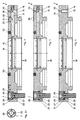
- Figure 1 is a quick release cylinder 1 with a cover 3 and stretched quick-release pallet shown.
- the quick release pallet In the left half of the figure is the quick release pallet is shown fixed, and is in the right half of the figure the quick release pallet is shown in a relaxed state. This can be seen under other on the tension state of the tension springs 6 and at the position of the retracted piston 5 of the quick release cylinder 1, and further at the distance between the quick release pallet and the cover 3 of the quick release cylinder 1. Regardless of this, however, the holes for the oil or air supply are corresponding supply systems.
- the quick release cylinder 1 is a rough description of the housing 2 and the cover 3 and the retractable nipple 4 and the piston 5 with the Tension springs 6 together.
- the cover 3 is opened with the fastening screws 7 screwed tightly to the housing 2 so that they form a unit.
- the Oil port 9 is used to supply hydraulic oil to relax the Quick release cylinder.
- the hydraulic oil flows through the oil connection 9 and through the oil supply bore 10 into the cylinder area, so that with increasing Oil pressure of the pistons of the quick release cylinder upwards against the spring force the tension springs 6 is pressed until it stops.
- the Retractable nipple 4 and the one with the fastening screw 38 on the retractable nipple 4th attached pallet 37 relaxed. During this relaxation process, a Distance between the contact surfaces of the quick release cylinder and the Palette.
- the compressed air connection 11 supplies the compressed air supply system of the Quick release cylinder with compressed air.
- the compressed air supply system exists from cross channels, cross holes, counterbores and punctures. From Compressed air connection 11 leads a cross hole to the transverse channel 12 which Cross bore 13 and the nozzle 52 supplied with compressed air. By doing so Distribution of the supplied compressed air can be done via a variable setting of the effective cross section of the nozzle 52 the air pressure in Compressed air supply system can be set.
- this recess 15 which forms the ring channel, is in dashed lines Execution shown in a circle.
- this Puncture 15 extending cross holes 16 are now arranged in one another cross channel 17 open.
- This transverse channel 17 ends in a recess 18 the one in the bore 36 for the nipple behind the receptacle for the locking ring 20 is arranged, and extends all around in the bore 36.
- FIG. 1.1 A detailed The illustration can be seen in FIG. 1.1.
- FIG. 1.1 shows the cover 3 in which the transverse channel 17 is arranged and up to extends into the groove 18.
- the puncture 18 is behind a puncture for the Segerring 20, however, directed radially outwards with a smaller dimension arranged.
- blow holes 19 open into the hole 36 run diagonally downwards from above. These blow-out holes 19 are all around the bore 36 arranged to run and are over the recess 18 of the also around the bore 36 is supplied with compressed air.
- the Retractable nipple 4 remains in the tensioned state of the quick release cylinder these blow-out bores 19 are closed to the outside. Once the Retractable nipple 4 is unlocked, ie pushed upwards by the piston 5 the blow-out holes 19 are exposed and the one located therein Compressed air can flow outside and initiate its cleaning function.
- the fastening screw 7 is in the left half of the figure shown, which runs exactly through the recess 15. Through the Arrangement of the hole through the recess 15 is a Compressed air supply in the area of the hole for the fastening screw 7 reached.
- the mounting screw 7 is designed so that it is in addition to Attaching the cover to the housing takes on a blow-out function. Detailed information on this function is in Figures 3, 4, 5 and associated enlarged representations.
- a nozzle 52 is shown which the retractable nipple 4, 42 with the Compressed air system connects.
- the retractable nipple 4 has a longitudinal bore 41 and equipped with at least one transverse bore 40, as also shown in FIG. 6. in the locked state, these holes are supplied with compressed air, but not can flow out, since the longitudinal bore 41 through the fastening screw 38th is closed, and the transverse bores 40 through the wall of the bore 36 are also closed for the nipple.
- the clamping nipple is moved upwards, and the Openings of the cross bores 40 are exposed. This can cause the compressed air flow out of the cross bores 40 and the one located in the air pressure system Air pressure drops suddenly.
- This function firstly blows out the affected area achieved, and secondly achieved a safety-related function, the one bullet-like lifting of the pallet from the quick release cylinder prevented.
- This bullet-like lifting movement results from small pallets or if no pallet is attached to the retractable nipple and this is only loose in the The quick release cylinder is inserted and the compressed air supply switched on becomes.
- the temporal component during which the retractable nipple 4 experiences this enormous acceleration Minimum restricted.
- the Air pressure in the compressed air system suddenly reduced. This also reduces the acceleration of the retractable nipple and the The extension speed of the retractable nipple is no longer increased on the contrary, the gravity of the nipple or the nipple is involved a pallet as a counter component that the extension speed of the Retractable nipple reduced again.
- the retractable nipple in FIG. 7 is constructed differently, it basically has same functionality. It consists of the nipple 42, a cylindrical one Collar stop 48 and a fastening screw 45.
- the Fastening screw 45 is a longitudinal bore 46 and one Cross bore 47, which in cooperation with a longitudinal groove 49, a Cross bore 50 and a recess 51 the previously described Mode of operation with regard to the blow-out and the safety-related Effect.
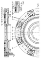
- Figure 2 shows a plan view of the quick release cylinder according to the invention with different embodiments of blow-out holes.
- the holes for receiving of mounting screws 7 include.
- Blow-out bores are also 25 shown in the ring channel already described, the recess 15 is executed.
- Islands 35 are shown in the left half of the illustration, into which a blow-out bore 25 also opens, which with the recess 15 in Connection is established.
- Another feature of the present invention shows an embodiment an island that has a slightly larger outer diameter than that Screw head of the fastening screw 7 represents. Between the head of the Fastening screw 7 and the round island 35 flows over a Longitudinal groove 29 compressed air from the recess 15.
- This embodiment differs from the embodiment with the segment-shaped islands only by the size of the contact area given by the surface of the islands is.
- the blow-out ring 23 is seen radially inward from these islands shown, which contains the blow-out holes 24.
- This blow-out ring 23 is through cross bores 22, cross bores 17 and a further cross bore 16 connected to the compressed air supply system.
- This embodiment The present invention may optionally be in addition to the islands and the blow-out holes arranged therein to support the blow-out device to be ordered.
- An advantage of the arrangement of this blow-out ring 23 is in the fact that the outgoing compressed air can be distributed even more specifically, and this produces an even better cleaning effect.
- the order the islands 35 described above, and the blow-out bores 24 and 25, and the longitudinal bore 28 in the mounting screw 7 can optionally symmetrical or asymmetrical above the ring-shaped Supply channel, which is formed by the recess 15, may be arranged.
- An additional blow-out device is seen radially inward on the Wall of the bore 36 arranged for the mounting nipple. It is about thereby around the blow-out holes 19 which are supplied with compressed air by the puncture 18 become. As already described, this recess 18 is in the bore 36 arranged all round, and lies behind the recess for the Segerring 20. The position and the dimensions of the recess are arranged so that the Segerring seals the puncture 18 to the bore 36. The only openings in the direction of the bore 36 are the blow-out bores 19 which are inclined upwards and are aligned towards the axial center. As long as the retractable nipple 4 in tense condition persists, these blow holes are closed and the Coming air cannot escape from it. As soon as the retractable nipple 4 is relaxed, this is raised and the blow holes 19 uncovered so that the compressed air flows out of these blow-out bores 19 and can perform its cleaning function.
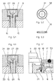
- FIG. 3 is a sectional view of a cover of the quick release cylinder shown.
- This blow-out bore 25 corresponds to an island representation in FIG. 2 in which an island 35 is shown which has the blow-out bore approximately in its center 25 has.
- From the cross bore 16 is directed radially inwards Cross bore 17 from which a further cross bore 22 Compressed air supply for the blow-out ring 23 causes.
- the mouth of the Cross bore 17 in the direction of bore 36 for the retractable nipple is provided, ends in the circumferential groove 18, which the Blow holes 19 supplied with compressed air.
- the O-ring is for sealing purposes 53 arranged around the bore 36.
- the left half of the illustration in FIG. 3 also shows the circumferential one Blow-out ring 23, and the fastening screw 7 in the provided Drilling.
- the fastening screw 7 is inserted vertically through the hole passes through the puncture 15 and takes on the one hand the function of Attachment of the cover to the housing, and on the other hand by a special embodiment of the fastening screw 7 a blow-out function.
- the fastening screw 7 has longitudinal grooves 29 and transverse grooves 30.
- the for the mounting screw 7 The proposed bore is made with a larger diameter, so that compressed air from the recess 15 along the thread and the trained passage 26 which is between the screw and the bore trains can flow upwards.
- this channel 26 opens Cross bore 27 with the longitudinal bore 28 in the fastening screw 7 are arranged, and on the other hand there is a connection between the Passage 26 and the transverse grooves 29 and longitudinal grooves 30 so that the Compressed air flowing through both from the center of the fastening screw and can also flow around the edge of the head of the fastening screw.
- the Figure 3.1 shows a view of the fastening screw from the thread side seen.
- FIG. 4 again shows a cross section of a cover for one Quick release cylinder in its right half in this embodiment has no blow-out ring 23, but the embodiment with the Fastening island shows, and the blow-out bore 25 outside of one Fastening island lies.
- the mounting island 35 is therefore in this representation behind the blow-out hole 25.
- the left half of the illustration is again the attachment with the mounting screw 7 recognizable, in which in a
- additional cross holes 33 and 34 in the cover 3 are arranged. Compressed air can now flow through these cross holes, which in turn is in a passage 39 located between the head of the Fastening screw and the hole forms, opens and so from the Lid of the quick release cylinder flows out.
- FIG. 5 again shows a sectional illustration of a cover for a Quick release cylinder in a further embodiment.
- the recess 15 can be seen in the illustration, into which the cross bore 16 opens, which supplies the blow-out bore 25 with compressed air.
- FIG. 4.1 shows an enlarged illustration of the fastening of the cover 3 on the housing 2 with the fastening screw 7.
- the fastening screw 7 is the longitudinal bore 28 and the transverse bore 27 shown.
- the passage 26 and the recess 15 are shown in the cover 3.
- the arranged in cover 3 cross hole 33 is used to supply compressed air via the Cross bore 34 in the passage 39 which is between cover 3 and the head the fastening screw 7 forms.
- FIG. 5.1 shows an enlarged section from FIG. 5.
- the venting device already works in the description of the figures explained in detail for FIG. 5.
- FIG. 8 shows a further embodiment of the present invention, in which a blow-out ring 54 in the lid of the Quick release cylinder 1 is arranged.
- This blow-out ring 54 is in place of the in Figure 3 blowout ring 23 provided.
- the blow-out ring 54 in that it is on his radial inside through a fit 58 in that provided in the cover Puncture is fixed and a defined small on its radial outer contour Has distance from the wall in the recess of the lid and thus forms a blow-out groove 56.
- there are 54 in the blow-out ring Blow-out bores 55 are arranged above that already described Supply system with air, or if necessary also with appropriate liquid, can be supplied.
- blow-out ring 54 on the a puncture directed radially outward toward the inside of the cover 59, which reduces the height of the blow-out ring 54 in that a All-round supply channel is created, which is between the floor the puncture in the lid in which the blow-out ring 54 is arranged and the Area of the blow-out ring 54, which is oriented towards the cover and is directed radially outward.
- the blow-out holes 55 are in three centric Ring arrangements performed, with a view from above on the Cover the blow-out holes 55 of the middle ring approximately perpendicular to the Cover level of the quick release cylinder are aligned, the Blow holes 55 of the interior of the three rings are arranged so that the outflowing medium emerges inwards from the vertical axis and that the blowout holes 55 of the exterior of the three rings are so arranged are that they are inclined outwards from the vertical axis, whereby the outflowing medium flows outwards. This will make a all-round cleaning effect when the medium is applied to the appropriate system achieved.
- blow-out groove 56 which is between the radial outer contour 62 of the blow-out ring 54 and the radial one
- the outer contour of the recess for the blow-out ring 54 extends.
- This blow-out groove 56 is formed by a corresponding gap, which is between the radial Outer contour 62 of the blow-out ring 54 and the radial outer contour of the recess extends for the blow-out ring 54.
- another puncture 61 is on the top of the blow-out ring 54, in which another O-ring 57 is arranged for sealing purposes. This O-ring 57 additionally prevents this Penetration of the loaded medium into the interior of the Quick release cylinder.
- the blow-out ring 54 is in a position opposite the Figure 8 modified embodiment shown. Basically, it is around the same blow-out ring, but with the additional radial outer contour 62 starting from the recess 59 starting towards the outside seen in the installed state is formed obliquely outwards. This already results in a flow angle for the escaping medium, which is directed radially outwards.
- the radial outer contour of the recess 63 for the blow-out ring 54 is included a corresponding, opposite to the perpendicular, angled surface formed so that there is an approximately parallel distance between the radial Outer contour 62 of the blow-out ring 54 and the radial outer contour of the recess 63 for the blow-out ring 54 results, resulting in an all-round channel forms, which in the lid from the inside outwards radially outwards is arranged progressively. This creates a leadership effect for that escaping medium, which is supplied by the supply system, at which - as already pointed out - is either air or a appropriate liquid.
- the attachment of this blow-out ring 54 corresponds to the embodiment in FIG. 8.
- the recess 59 is also realized according to the embodiment in Figure 8, so that the essential difference between the two embodiments in Figure 8 and 9 therein shows that the radial outer contour 62 of the blow-out ring 54 and the radial outer contour 63 of the recess for the blow-out ring 54 opposite the Vertical at an angle that extends obliquely outwards Embodiment according to Figure 9 is executed and in the embodiment according to Figure 8 is approximately vertical.
- the outflowing medium occurs approximately perpendicular from the surface of the Quick release cylinder.
- the angle of inclination compared to the perpendicular for the radial outer contours 62 and 63 can depend on the application be executed differently.
- FIG. 10 shows a section of a top view of the embodiment according to FIGS Figures 8 and 9 shown. So this is the top view of a cover of a quick release cylinder, in which a blow-out ring 54 is arranged is.
- This blow-out ring 54 has three areas in which blow-out bores 55 are arranged radially. The detailed information about these blow-out holes have already been explained in detail in the description of FIGS. 8 and 9.
- the fit 58 is opposite on the radially inner side of the blow-out ring 54 the radially inner wall of the recess in the cover for the blow-out ring 54 realized. By means of this fit 58, the blow-out ring 54 is on the cover of the Quick release cylinder attached.
Landscapes
- Engineering & Computer Science (AREA)
- Mechanical Engineering (AREA)
- Chemical & Material Sciences (AREA)
- Chemical Kinetics & Catalysis (AREA)
- Electrochemistry (AREA)
- Auxiliary Devices For Machine Tools (AREA)
- Jigs For Machine Tools (AREA)
- Nozzles (AREA)
- Cleaning In General (AREA)
- Drilling And Boring (AREA)
Abstract
Description
- Figur 1:
- einen Querschnitt eines Schnellspannzylinders mit Deckel und aufgespannter Palette
- Figur 1.1:
- einen Ausschnitt aus Figur 1
- Figur 2:
- eine Draufsicht auf einen Schnellspannzylinder
- Figur 3:
- einen Querschnitt eines Deckel eines Schnellspannzylinders
- Figur 3.1:
- die Unteransicht einer Befestigungsschraube
- Figur 4:
- einen Querschnitt des Deckels eines Schnellspannzylinders
- Figur 4.1:
- einen Ausschnitt aus Figur 4
- Figur 5:
- eine Schnittdarstellung eines Deckels eines Schnellspannzylinders
- Figur 5.1:
- einen Ausschnitt aus Figur 5
- Figur 5.2:
- Draufsicht auf einen Zentrierring
- Figur 5.3:
- eine Schnittdarstellung eines Zentrierringes
- Figur 6
- : eine Ausführungsform eines Einzugsnippels
- Figur 7:
- eine Ausführungsform eines Einzugsnippels
- Figur 8:
- einen Querschnitt des Deckkels eines Schnellspannzylinder in einer weiteren Ausführungsform
- Figur 9:
- einen Querschnitt eines Deckels eines Schnellspannzylinders in einer weiteren Ausführungsform
- Figur 10:
- die Draufsicht in geschnittener Darstellung auf die Ausführungsformen nach den Figuren 8 und 9.
- 1.
- Schnellspannzylinder
- 2.
- Gehäuse
- 3.
- Deckel
- 4.
- Einziehnippel
- 5.
- Kolben
- 6.
- Spannfeder
- 7.
- Befestigungsschraube
- 8.
- Zentrierscheibe
- 9.
- Ölanschluß
- 10.
- Ölzuführbohrung
- 11.
- Druckluftanschluss
- 12.
- Querkanal
- 13.
- Kreuzbohrung
- 14.
- Senkung
- 15.
- Einstich
- 16.
- Kreuzbohrung
- 17.
- Querkanal
- 18.
- Einstich
- 19.
- Ausblasbohrung
- 20.
- Segerring
- 21.
- Kolbendichtung
- 22.
- Kreuzbohrung
- 23.
- Ausblasring
- 24.
- Ausblasbohrung
- 25.
- Ausblasbohrung
- 26.
- Durchlaß
- 27.
- Querbohrung
- 28.
- Längsbohrung
- 29.
- Längsnut
- 30.
- Quernut
- 31.
- Längsnut
- 32.
- Quernut
- 33.
- Kreuzbohrung
- 34.
- Kreuzbohrung
- 35.
- Insel
- 36.
- Bohrung f Nippel
- 37.
- Palette
- 38.
- Befestigungsschraube
- 39.
- Durchlaß
- 40.
- Querbohrung
- 41.
- Längsbohrung
- 42.
- Nippel
- 43.
- Querbohrung
- 44.
- Längsbohrung
- 45.
- Befestigungsschraube
- 46.
- Längsbohrung
- 47.
- Querbohrung
- 48.
- Bundanschlag
- 49.
- Längsnut
- 50.
- Querbohrung
- 51.
- Einstich
- 52.
- Düse
- 53.
- O-Ring
- 54.
- Ausblasring
- 55.
- Ausblasbohrungen
- 56.
- Ausblasnut
- 57.
- O-Ring
- 58.
- Passung
- 59.
- Einstich
- 60.
- Anphasung
- 61.
- Einstich
- 62.
- radiale Außenkontur (54)
- 63.
- Einstich
Claims (26)
- Verfahren zum Ausblasen und Ausspritzen von Verunreinigungen von der Oberfläche eines Schnellspannzylinders und den darauf angeordneten Funktionseinheiten, wobei der Schnellspannzylinder im Wesentlichen aus einem Gehäuse, einem Deckel, Befestigungsschrauben, einem Kolben, Spannfedern und einem Einziehnippel, zum Festspannen einer Palette besteht, dadurch gekennzeichnet, dass ein mit Druckluft versorgtes Druckluftversorgungssystem die gezielte Verteilung von Druckluft innerhalb des Schnellspannzylinders für Reinigungszwecke, zum Schutz vor Verunreinigungen beim Werkzeug- und Werkstückwechsel, sowie sicherheitstechnische Funktionen beim Entspannen des Schnellspannzylinders übernimmt.
- Verfahren nach Anspruch 1, dadurch gekennzeichnet, dass das Druckluftversorgungssystem die zugeführte Druckluft in mehrere Versorgungseinheiten aufteilt.
- Verfahren nach einem der beiden Ansprüche 1 und 2, dadurch gekennzeichnet, dass die zugeführte Druckluft sowohl aus Ausblasbohrungen (19, 24, 25), Durchlässen (39), wie auch aus Querbohrungen (40, 43) gezielt entströmt und dadurch die Oberfläche des Schnellspannzylinders sowie auch die Auflagefläche der aufgespannten Palette von Verunreinigungen befreit.
- Verfahren nach einem der vorhergehenden Ansprüche, dadurch gekennzeichnet, dass durch die Öffnungen jener Auslassbohrungen (24 und 25), die in einer tieferen Ebene als die Auflagefläche der Inseln (35) gegenüber der Auflagefläche der Palette liegen, auch bei aufgespannter Palette Druckluft entweicht, und somit bereits einen vorreinigenden Effekt durch das Ausblasen von Druckluft vor dem Entspannen des Spannzylinders bewirken.
- Verfahren nach einem der Ansprüche 1 bis 3, dadurch gekennzeichnet, dass aus Auslassbohrungen (25) und Durchlässen (26) Druckluft entströmt, sobald die Palette vom Spannzylinder abgehoben wird, wobei die höchste Fliessgeschwindigkeit der Druckluft im Augenblick des Abhebens der Palette durch den minimalen Abstand zwischen Palette und Auflagefläche des Schnellspannzylinders erreicht wird und dadurch die grösstmögliche Reinigungswirkung in diesem Augenblick erfolgt, der sich auch beim Festspannen der Palette in umgekehrter Reihenfolge wiederholt, und dabei evtl. festgeklebte Verunreinigungen oder Bohrspäne sowohl von der Palette als auch vom Schnellspannzylinder wegbläst.
- Verfahren nach einem der Ansprüche 1 bis 3, dadurch gekennzeichnet, dass der Einziehnippel (4, 42, 48) beim Entspannen des Schnellspannzylinders Druckluft durch seine Längsbohrung (41, 46) und seine Querbohrung (40, 43) schlagartig abbläst, und dadurch einen Ausblaseffekt für den Schnellspannzylinder und die darauf aufgespannte Palette erzeugt.
- Verfahren nach einem der Ansprüche 1 bis 3 und 7, dadurch gekennzeichnet, dass durch das schlagartige Austreten der Druckluft aus der Querbohrung (40, 43) des Einziehnippels (4) eine schlagartige Druckreduzierung der Druckluft erfolgt, wodurch die Ausfahrbeschleunigung des Einziehnippels beim Entspannen des Schnellspannzylinders abrupt beendet wird, und infolge dessen sich die Ausfahrgeschwindigkeit des Einziehnippels nicht mehr weiter erhöht, wodurch der Einziehnippel auch im unbelasteten Zustand keine geschossartige Ausfahrbewegung durchführen kann.
- Vorrichtung zum Ausblasen und Ausspritzen von Verunreinigungen von der Oberfläche eines Schnellspannzylinders und den darauf angeordneten Funktionseinheiten, wobei der Schnellspannzylinder im Wesentlichen aus einem Gehäuse, einem Deckel, Befestigungsschrauben, einem Kolben, Spannfedern und einem Einziehnippel, zum Festspannen einer Palette besteht, dadurch gekennzeichnet, dass der Schnellspannzylinder (1) ein Druckluftversorgungssystem aufweist, das aus Druckluftanschluss (11), Querbohrungen (12, 17, 27, 40 und 43), Kreuzbohrungen (13, 22), Einstichen (15, 18), Längsbohrungen (28, 46), sowie Auslassbohrungen (18, 24, 25), und Durchlässen (26, 39) besteht.
- Vorrichtung nach Anspruch 8, dadurch gekennzeichnet, dass der Einstich (15) im Deckel (3) ungefähr kreisförmig rundumlaufend an seiner unteren auf dem Gehäuse aufliegenden Fläche angeordnet ist.
- Nach einem der Ansprüche 8 und 9, dadurch gekennzeichnet, dass vom Einstich (15) ausgehend mindestens eine Kreuzbohrung (16) in axialer Richtung im Deckel (2) verläuft, in die mindestens eine Querbohrung (17) radial von aussen nach innen bis zu einem Einstich (18) reicht, der ebenfalls im Zylinderdeckel (2) in der Bohrung (36) radial auswärtsgerichtet hinter einem Einstich für den Segerring (20) angeordnet ist, von dem ausgehend schräg zentral nach oben gerichtet Auslassbohrungen in die Bohrung (36) hineinreichen.
- Vorrichtung nach Anspruch 10, dadurch gekennzeichnet, dass die Ausblasbohrungen (19) rundumlaufend, etwa symmetrisch in entsprechender Anzahl angeordnet unterhalb der Oberkante der Bohrung (36) münden.
- Vorrichtung nach einem der Ansprüche 8 und 9, dadurch gekennzeichnet, dass die Bohrung für die Aufnahme der Befestigungsschraube (7) im Deckel (3) senkrecht durch den rundumlaufenden, einen Ringkanal bildenden, Einstich (15) hindurchgehen, und in entsprechender Anzahl über die Oberfläche des Deckels des Schnellspannzylinders verteilt sind.
- Nach einem der Ansprüche 8, 9 und 12, dadurch gekennzeichnet, dass die Befestigungsschrauben (7) durchgängig verbundene Querbohrungen (27) und Längsbohrung (28) aufweisen, wobei die Querbohrung (27) im Durchlass (26) mündet, der mit dem Einstich (15) durchgängig verbunden ist, und die Längsbohrung (28) in der Mitte des Schraubenkopfes der Befestigungsschraube (7) ausmündet, und somit einen durchgängigen Kanal vom Einstich 15 bis an die Oberfläche des Schnellspannzylinders bilden.
- Vorrichtung nach einem der Ansprüche 8, 9 und 13, dadurch gekennzeichnet, dass die Durchführungsbohrung zur Aufnahme der Befestigungsschraube (7) im Deckel (3) mit einem derartig grossen Durchmesser gefertigt ist, dass sich zwischen dem Kopf der Befestigungsschraube und der Wandung im Bohrloch ein Durchlass (39) ausbildet, und dass die Bohrung für die Aufnahme der Befestigungsschraube im Bereich des Gewindes entsprechend gross gefertigt ist, dass sich ein Durchlass (26) zwischen der Aussenwandung des Deckels (3) und dem Gewinde der Befestigungsschraube (7) ausbildet.
- Nach einem der Ansprüche 8, 9, 14 und 15, dadurch gekennzeichnet, dass von der Unterseite des Deckels (3) Kreuzbohrungen (33 und 34) um den Umfang des Durchlasses (39) verteilt so angeordnet sind, dass die Kreuzbohrungen (33 und 34) im Durchlass (39) münden und damit einen durchgängigen Kanal zwischen dem Einstich (15) und der Oberfläche des Deckels des Schnellspannzylinders bilden.
- Vorrichtung nach einem der Ansprüche 8, 9 und 12 bis 15, dadurch gekennzeichnet, dass die Befestigungsschraube (7) mit wenigstens einer Längsnut (29) und einer Quernut (30) versehen ist, die den Austritt der Druckluft aus dem Durchlass (26) an die Oberseite des Deckels des Schnellspannzylinders ermöglicht.
- Vorrichtung nach einem der Ansprüche 8, 9 und 12 bis 1, dadurch gekennzeichnet, dass eine Zentrierscheibe (8) eine Befestigungsschraube (7) aufnimmt, wobei die Zentrierscheibe (8) mit wenigstens einer Längsnut (31) und wenigstens einer Quernut (32) versehen ist, durch diese die Druckluft aus dem Durchlass (26) in den Durchlass (39) einströmen und an die Oberfläche des Deckels des Zylinders ausströmen kann.
- Vorrichtung nach einem der Ansprüche 8, 9 dadurch gekennzeichnet, dass eine Kreuzbohrung (22) von der Querbohrung (17) in einen Einstich, der zur Aufnahme eines Ausblasringes (23,54) vorgesehen ist mündet und die Druckluft durch die Ausblasbohrungen (24,55) die ungefähr ringförmig auf dem Ausblasring angeordnet sind, ausströmt.
- Vorrichtung nach einem der vorhergehenden Ansprüche, dadurch gekennzeichnet, daß ein Ausblasring (54) Ausblasbohrungen (55) aufweist, dessen Öffnungen ungefähr ringförmig an dessen Oberfläche angeordnet sind, wobei die Bohrungen teilweise vertikal zur Oberfläche des Ausblasrings (54) und teilweise nach innen und teilweise nach außen gegenüber der Vertikalen geneigt ausgebildet sind.
- Vorrichtung nach einem der vorhergehenden Ansprüche, dadurch gekennzeichnet, daß der Ausblasring (54) zwischen seiner radialen Außenkontur (62) und der radialen Außenkontur des Einstichs (63) für den Ausblasring (54) im Deckel des Schnellspannzylinders (1) eine Ausblasnut (56) ausbildet.
- Vorrichtung nach einem der vorhergehenden Ansprüche, dadurch gekennzeichnet, daß eine Ausblasnut (56) in etwa vertikal zur Oberfläche des Deckels des Schnellspannzylinders (1) ausgerichtet ist.
- Vorrichtung nach einem der vorhergehenden Ansprüche, dadurch gekennzeichnet, daß eine Ausblasnut (56) gegenüber der Vertikalen zur Oberfläche des Deckels des Schnellspannzylinders (1) auswärts geneigt ausgerichtet ist.
- Vorrichtung nach einem der vorhergehenden Ansprüche, dadurch gekennzeichnet, daß der Ausblasring (54) einen Einstich (59) aufweist, welcher sich an der dem Deckel des Schnellspannzylinders (1) zugewandten Seite im radial äußeren Bereich erstreckt.
- Vorrichtung nach einem der vorhergehenden Ansprüche, dadurch gekennzeichnet, daß der Ausblasring (54) an seiner Oberseite einen O-Ring (57) aufweist.
- Vorrichtung nach einem der vorgehenden Ansprüche, dadurch gekennzeichnet, dass im Boden des Kolbens im Bereich seiner Längsachse eine Düse (52) angeordnet ist, die die Längsbohrung (41) des Einziehnippels (4) mit Druckluft versorgt.
- Vorrichtung nach einem der vorhergehenden Ansprüche, dadurch gekennzeichnet, dass der Durchmesser der Bohrung in der Düse (52) die Druckverteilung des Luftdrucks im Druckluftversorgungssystem regelt.
Applications Claiming Priority (2)
| Application Number | Priority Date | Filing Date | Title |
|---|---|---|---|
| DE19841928 | 1998-09-14 | ||
| DE19841928A DE19841928C2 (de) | 1998-09-14 | 1998-09-14 | Vorrichtung zur Beseitigung von Verunreinigungen an Schnellspanneinheiten |
Publications (3)
| Publication Number | Publication Date |
|---|---|
| EP1005936A2 true EP1005936A2 (de) | 2000-06-07 |
| EP1005936A3 EP1005936A3 (de) | 2002-10-09 |
| EP1005936B1 EP1005936B1 (de) | 2003-06-11 |
Family
ID=7880845
Family Applications (1)
| Application Number | Title | Priority Date | Filing Date |
|---|---|---|---|
| EP99117641A Revoked EP1005936B1 (de) | 1998-09-14 | 1999-09-08 | Ausblas- und Ausspritzeinrichtung für Schnellspannzylinder mit Deckel |
Country Status (4)
| Country | Link |
|---|---|
| EP (1) | EP1005936B1 (de) |
| JP (1) | JP2000094262A (de) |
| AT (1) | ATE242670T1 (de) |
| DE (2) | DE19841928C2 (de) |
Cited By (4)
| Publication number | Priority date | Publication date | Assignee | Title |
|---|---|---|---|---|
| DE10317346B4 (de) * | 2003-04-15 | 2020-02-20 | Andreas Maier Gmbh & Co. Kg | Halterungssystem einer Trägerplatte in Schnellspannzylindern |
| CN113103024A (zh) * | 2021-05-10 | 2021-07-13 | 大昌汽车部件股份有限公司 | 一种卡钳活塞的钻孔装置及加工方法 |
| CN114850548A (zh) * | 2022-04-25 | 2022-08-05 | 成都四威高科技产业园有限公司 | 太赫兹波导口部毛刺去除工艺 |
| CN118269029A (zh) * | 2024-06-04 | 2024-07-02 | 无锡星微科技有限公司杭州分公司 | 反馈系统具有角度调整机构 |
Families Citing this family (14)
| Publication number | Priority date | Publication date | Assignee | Title |
|---|---|---|---|---|
| DE19917484A1 (de) * | 1999-04-17 | 2000-10-26 | Emil Stark | Befestigung eines Einzugsnippels an einem Werkstück oder einer Trägerplatte |
| DE20009117U1 (de) | 2000-05-23 | 2000-08-10 | Vischer & Bolli AG, Dübendorf | Spannzylinder |
| DE10036885A1 (de) * | 2000-07-28 | 2002-02-07 | Roemheld A Gmbh & Co Kg | Schnellspanneinheit |
| DE20021047U1 (de) | 2000-12-13 | 2001-03-15 | Vischer & Bolli AG, Dübendorf | Spanneinrichtung |
| DE10116229A1 (de) | 2001-04-02 | 2002-10-10 | Mecatool Ag Flawil | Vorrichtung zum lösbaren Halten von Werkstücken an Bearbeitungseinrichtungen |
| DE10127207A1 (de) * | 2001-06-05 | 2002-12-12 | Stark Spannsysteme Gmbh Goetzi | Spannvorrichtung |
| DK1344599T3 (da) * | 2002-03-11 | 2004-10-04 | Erowa Ag | Spændindretning med en centrerpatron og en spændtap, som kan fastspændes deri |
| ATE297286T1 (de) * | 2002-09-09 | 2005-06-15 | Hermle Berthold Maschf Ag | Festspanneinrichtung zum festspannen zweier teile aneinander |
| DE102005052780B4 (de) * | 2005-11-05 | 2019-05-09 | Andreas Maier Gmbh & Co. Kg | Schnellspann-Zylinder mit Verriegelungskontrolle |
| CH708458B1 (de) * | 2013-08-20 | 2017-09-29 | Erowa Ag | Spanneinrichtung. |
| DE102013222089A1 (de) * | 2013-10-30 | 2015-04-30 | Trumpf Sachsen Gmbh | Kupplungsvorrichtung und Kupplungsanordnung zum Verbinden zweier Bauteile einer maschinellen Anordnung für die Werkstückbearbeitung, insbesondere für die Blechbearbeitung |
| CN110948271A (zh) * | 2019-12-27 | 2020-04-03 | 大连瑞谷科技有限公司 | 具有吹扫功能的夹持工装 |
| JP7309638B2 (ja) * | 2020-03-12 | 2023-07-18 | 株式会社神戸製鋼所 | 収納容器 |
| DE102023113086A1 (de) * | 2023-05-17 | 2024-11-21 | Heinz-Dieter Schunk Gmbh & Co. Spanntechnik Kg | Spannstation, Grundplatte und Verteilscheibe |
Family Cites Families (5)
| Publication number | Priority date | Publication date | Assignee | Title |
|---|---|---|---|---|
| DE29615613U1 (de) * | 1996-09-09 | 1997-08-28 | Stark, Emil, Götzis | Spannvorrichtung zum Spannen eines Schnellspannzylinders auf einer Trägerplatte für Bearbeitungsmaschinen |
| DE19636375A1 (de) * | 1996-09-09 | 1998-03-12 | Emil Stark | Schnellverschluß für eine Palette unter Späneflug |
| DE19705686A1 (de) * | 1997-02-14 | 1998-08-20 | Emil Stark | Verfahren zur Herstellung einer Palette zur Werkstückbearbeitung und nach dem Verfahren hergestellte Palette |
| DE29722730U1 (de) * | 1997-12-23 | 1998-02-26 | Vischer & Bolli AG, Dübendorf | Spanneinrichtung zur Fixierung eines Einzugsnippels an einer Aufspannplatte |
| DE19834040C2 (de) * | 1998-07-29 | 2002-01-17 | Stark Werkzeuggesellschaft M B | Deckelloser Schnellspannzylinder |
-
1998
- 1998-09-14 DE DE19841928A patent/DE19841928C2/de not_active Expired - Lifetime
-
1999
- 1999-09-08 EP EP99117641A patent/EP1005936B1/de not_active Revoked
- 1999-09-08 AT AT99117641T patent/ATE242670T1/de not_active IP Right Cessation
- 1999-09-08 DE DE59905917T patent/DE59905917D1/de not_active Expired - Fee Related
- 1999-09-14 JP JP11261159A patent/JP2000094262A/ja active Pending
Cited By (4)
| Publication number | Priority date | Publication date | Assignee | Title |
|---|---|---|---|---|
| DE10317346B4 (de) * | 2003-04-15 | 2020-02-20 | Andreas Maier Gmbh & Co. Kg | Halterungssystem einer Trägerplatte in Schnellspannzylindern |
| CN113103024A (zh) * | 2021-05-10 | 2021-07-13 | 大昌汽车部件股份有限公司 | 一种卡钳活塞的钻孔装置及加工方法 |
| CN114850548A (zh) * | 2022-04-25 | 2022-08-05 | 成都四威高科技产业园有限公司 | 太赫兹波导口部毛刺去除工艺 |
| CN118269029A (zh) * | 2024-06-04 | 2024-07-02 | 无锡星微科技有限公司杭州分公司 | 反馈系统具有角度调整机构 |
Also Published As
| Publication number | Publication date |
|---|---|
| DE59905917D1 (de) | 2003-07-17 |
| EP1005936B1 (de) | 2003-06-11 |
| DE19841928C2 (de) | 2003-03-20 |
| EP1005936A3 (de) | 2002-10-09 |
| DE19841928A1 (de) | 2000-03-16 |
| ATE242670T1 (de) | 2003-06-15 |
| JP2000094262A (ja) | 2000-04-04 |
Similar Documents
| Publication | Publication Date | Title |
|---|---|---|
| EP1005936B1 (de) | Ausblas- und Ausspritzeinrichtung für Schnellspannzylinder mit Deckel | |
| EP0827806B1 (de) | Spannzylinder zum Spannen eines Einzugsnippels, Einzugsnippel hierfür und Spannsystem zur Verwendung unter Späneflug | |
| EP1268123B1 (de) | Vorrichtung zum lösbaren halten von werkstücken an bearbeitungseinrichtungen | |
| DE19834040C2 (de) | Deckelloser Schnellspannzylinder | |
| DE102010005886B4 (de) | Spannvorrichtung mit einem Höhenausgleich | |
| EP3829802A1 (de) | Drehwerkzeug-halter | |
| EP0724486A1 (de) | Sprühblock eines sprühwerkzeugs | |
| EP1615744A1 (de) | Schnellspannzylinder in modulbauweise | |
| DE19920291A1 (de) | Kupplungssystem für den Anschluß maschinenseitiger Versorgungsleitungen für Medien aller Art inkl. elektrischer Leitungen zwichen Werkzeugmaschinen und daran angekoppeltem Werkstückträger | |
| DE60012863T2 (de) | Montagewerkzeug für ein hydromechanisches Futter | |
| DE102004006418A1 (de) | Schnellspannzylinder mit Sicherheitsvorrichtung gegen Blockierung | |
| EP0925872A2 (de) | Spanneinrichtung zur Fixierung eines Einzugsnippels an einer Aufspannplatte | |
| DE102013218050A1 (de) | Spannvorrichtung zum Einspannen mindestens eines Spannnippels | |
| DE10317339B4 (de) | Spannsystem mit Adapterteil | |
| EP1743733A1 (de) | Schnellspann-Vorrichtung mit Austauschzylinder | |
| EP1060873A2 (de) | Werkzeuganordnung zur Herstellung von ringförmigen Presslingen mit Hilfe einer Rundläuferpresse | |
| DE3405743A1 (de) | Vorrichtung zum greifen von bauteilen | |
| DE10317336A1 (de) | Schnellspannzylinder mit Ausblasung | |
| EP0849034B1 (de) | Kupplungsvorrichtung | |
| DE602005005010T2 (de) | Vorrichtung zum Bruchtrennen des Kopflagers einer Pleuelstange | |
| DE4434511A1 (de) | Auswerfervorrichtung für Thermoformwerkzeuge | |
| DE19508211C2 (de) | Ventilpatrone sowie deren Verwendung in einer Vakuumspanneinrichtung | |
| DE202010012368U1 (de) | Befestigungseinheit zur schweißtechnischen Verbindung einer Befestigungseinheit mit einem Bauteil | |
| DE10317346B4 (de) | Halterungssystem einer Trägerplatte in Schnellspannzylindern | |
| EP3450090A1 (de) | Luftkissentisch |
Legal Events
| Date | Code | Title | Description |
|---|---|---|---|
| PUAI | Public reference made under article 153(3) epc to a published international application that has entered the european phase |
Free format text: ORIGINAL CODE: 0009012 |
|
| AK | Designated contracting states |
Kind code of ref document: A2 Designated state(s): AT BE CH CY DE DK ES FI FR GB GR IE IT LI LU MC NL PT SE |
|
| AX | Request for extension of the european patent |
Free format text: AL;LT;LV;MK;RO;SI |
|
| RAP1 | Party data changed (applicant data changed or rights of an application transferred) |
Owner name: STARK WERKZEUGGESELLSCHAFT MBH |
|
| RIN1 | Information on inventor provided before grant (corrected) |
Inventor name: STARK WERKZEUGGESELLSCHAFT MBH |
|
| RAP1 | Party data changed (applicant data changed or rights of an application transferred) |
Owner name: STARK SPANNSYSTEME GMBH |
|
| RIN1 | Information on inventor provided before grant (corrected) |
Inventor name: STARK SPANNSYSTEME GMBH |
|
| PUAL | Search report despatched |
Free format text: ORIGINAL CODE: 0009013 |
|
| RIN1 | Information on inventor provided before grant (corrected) |
Inventor name: STARK, EMIL |
|
| AK | Designated contracting states |
Kind code of ref document: A3 Designated state(s): AT BE CH CY DE DK ES FI FR GB GR IE IT LI LU MC NL PT SE |
|
| AX | Request for extension of the european patent |
Free format text: AL;LT;LV;MK;RO;SI |
|
| RIC1 | Information provided on ipc code assigned before grant |
Free format text: 7B 23B 31/30 A, 7B 23B 31/107 B, 7B 23Q 11/00 B, 7B 23Q 1/00 B, 7B 23H 7/26 B |
|
| 17P | Request for examination filed |
Effective date: 20020824 |
|
| GRAH | Despatch of communication of intention to grant a patent |
Free format text: ORIGINAL CODE: EPIDOS IGRA |
|
| 17Q | First examination report despatched |
Effective date: 20021023 |
|
| GRAH | Despatch of communication of intention to grant a patent |
Free format text: ORIGINAL CODE: EPIDOS IGRA |
|
| GRAA | (expected) grant |
Free format text: ORIGINAL CODE: 0009210 |
|
| AK | Designated contracting states |
Designated state(s): AT BE CH CY DE DK ES FI FR GB GR IE IT LI LU MC NL PT SE |
|
| PG25 | Lapsed in a contracting state [announced via postgrant information from national office to epo] |
Ref country code: NL Free format text: LAPSE BECAUSE OF FAILURE TO SUBMIT A TRANSLATION OF THE DESCRIPTION OR TO PAY THE FEE WITHIN THE PRESCRIBED TIME-LIMIT Effective date: 20030611 Ref country code: IT Free format text: LAPSE BECAUSE OF FAILURE TO SUBMIT A TRANSLATION OF THE DESCRIPTION OR TO PAY THE FEE WITHIN THE PRESCRIBED TIME-LIMIT;WARNING: LAPSES OF ITALIAN PATENTS WITH EFFECTIVE DATE BEFORE 2007 MAY HAVE OCCURRED AT ANY TIME BEFORE 2007. THE CORRECT EFFECTIVE DATE MAY BE DIFFERENT FROM THE ONE RECORDED. Effective date: 20030611 Ref country code: IE Free format text: LAPSE BECAUSE OF FAILURE TO SUBMIT A TRANSLATION OF THE DESCRIPTION OR TO PAY THE FEE WITHIN THE PRESCRIBED TIME-LIMIT Effective date: 20030611 Ref country code: GB Free format text: LAPSE BECAUSE OF FAILURE TO SUBMIT A TRANSLATION OF THE DESCRIPTION OR TO PAY THE FEE WITHIN THE PRESCRIBED TIME-LIMIT Effective date: 20030611 Ref country code: FR Free format text: LAPSE BECAUSE OF FAILURE TO SUBMIT A TRANSLATION OF THE DESCRIPTION OR TO PAY THE FEE WITHIN THE PRESCRIBED TIME-LIMIT Effective date: 20030611 Ref country code: FI Free format text: LAPSE BECAUSE OF FAILURE TO SUBMIT A TRANSLATION OF THE DESCRIPTION OR TO PAY THE FEE WITHIN THE PRESCRIBED TIME-LIMIT Effective date: 20030611 |
|
| REG | Reference to a national code |
Ref country code: GB Ref legal event code: FG4D Free format text: NOT ENGLISH |
|
| REG | Reference to a national code |
Ref country code: CH Ref legal event code: EP |
|
| AKX | Designation fees paid |
Designated state(s): AT BE CH CY DE DK ES FI FR GB GR IE IT LI LU MC NL PT SE |
|
| REG | Reference to a national code |
Ref country code: IE Ref legal event code: FG4D Free format text: GERMAN |
|
| REF | Corresponds to: |
Ref document number: 59905917 Country of ref document: DE Date of ref document: 20030717 Kind code of ref document: P |
|
| REG | Reference to a national code |
Ref country code: CH Ref legal event code: NV Representative=s name: BOVARD AG PATENTANWAELTE |
|
| PG25 | Lapsed in a contracting state [announced via postgrant information from national office to epo] |
Ref country code: LU Free format text: LAPSE BECAUSE OF NON-PAYMENT OF DUE FEES Effective date: 20030908 Ref country code: CY Free format text: LAPSE BECAUSE OF FAILURE TO SUBMIT A TRANSLATION OF THE DESCRIPTION OR TO PAY THE FEE WITHIN THE PRESCRIBED TIME-LIMIT Effective date: 20030908 |
|
| PG25 | Lapsed in a contracting state [announced via postgrant information from national office to epo] |
Ref country code: SE Free format text: LAPSE BECAUSE OF FAILURE TO SUBMIT A TRANSLATION OF THE DESCRIPTION OR TO PAY THE FEE WITHIN THE PRESCRIBED TIME-LIMIT Effective date: 20030911 Ref country code: PT Free format text: LAPSE BECAUSE OF FAILURE TO SUBMIT A TRANSLATION OF THE DESCRIPTION OR TO PAY THE FEE WITHIN THE PRESCRIBED TIME-LIMIT Effective date: 20030911 Ref country code: GR Free format text: LAPSE BECAUSE OF FAILURE TO SUBMIT A TRANSLATION OF THE DESCRIPTION OR TO PAY THE FEE WITHIN THE PRESCRIBED TIME-LIMIT Effective date: 20030911 Ref country code: DK Free format text: LAPSE BECAUSE OF FAILURE TO SUBMIT A TRANSLATION OF THE DESCRIPTION OR TO PAY THE FEE WITHIN THE PRESCRIBED TIME-LIMIT Effective date: 20030911 |
|
| PG25 | Lapsed in a contracting state [announced via postgrant information from national office to epo] |
Ref country code: ES Free format text: LAPSE BECAUSE OF FAILURE TO SUBMIT A TRANSLATION OF THE DESCRIPTION OR TO PAY THE FEE WITHIN THE PRESCRIBED TIME-LIMIT Effective date: 20030922 |
|
| PGFP | Annual fee paid to national office [announced via postgrant information from national office to epo] |
Ref country code: AT Payment date: 20030922 Year of fee payment: 5 |
|
| PGFP | Annual fee paid to national office [announced via postgrant information from national office to epo] |
Ref country code: CH Payment date: 20030923 Year of fee payment: 5 |
|
| PG25 | Lapsed in a contracting state [announced via postgrant information from national office to epo] |
Ref country code: MC Free format text: LAPSE BECAUSE OF NON-PAYMENT OF DUE FEES Effective date: 20030930 Ref country code: BE Free format text: LAPSE BECAUSE OF NON-PAYMENT OF DUE FEES Effective date: 20030930 |
|
| NLV1 | Nl: lapsed or annulled due to failure to fulfill the requirements of art. 29p and 29m of the patents act | ||
| GBV | Gb: ep patent (uk) treated as always having been void in accordance with gb section 77(7)/1977 [no translation filed] |
Effective date: 20030611 |
|
| PGFP | Annual fee paid to national office [announced via postgrant information from national office to epo] |
Ref country code: DE Payment date: 20031216 Year of fee payment: 5 |
|
| REG | Reference to a national code |
Ref country code: IE Ref legal event code: FD4D |
|
| PLBQ | Unpublished change to opponent data |
Free format text: ORIGINAL CODE: EPIDOS OPPO |
|
| PLBI | Opposition filed |
Free format text: ORIGINAL CODE: 0009260 |
|
| PLAB | Opposition data, opponent's data or that of the opponent's representative modified |
Free format text: ORIGINAL CODE: 0009299OPPO |
|
| BERE | Be: lapsed |
Owner name: *STARK SPANNSYSTEME G.M.B.H. Effective date: 20030930 |
|
| PLAX | Notice of opposition and request to file observation + time limit sent |
Free format text: ORIGINAL CODE: EPIDOSNOBS2 |
|
| 26 | Opposition filed |
Opponent name: GEORG FISCHER AG Effective date: 20040311 |
|
| R26 | Opposition filed (corrected) |
Opponent name: GEORG FISCHER AG Effective date: 20040310 |
|
| EN | Fr: translation not filed | ||
| PLAX | Notice of opposition and request to file observation + time limit sent |
Free format text: ORIGINAL CODE: EPIDOSNOBS2 |
|
| RDAF | Communication despatched that patent is revoked |
Free format text: ORIGINAL CODE: EPIDOSNREV1 |
|
| RDAG | Patent revoked |
Free format text: ORIGINAL CODE: 0009271 |
|
| STAA | Information on the status of an ep patent application or granted ep patent |
Free format text: STATUS: PATENT REVOKED |
|
| REG | Reference to a national code |
Ref country code: CH Ref legal event code: PL |
|
| 27W | Patent revoked |
Effective date: 20041018 |
|
| PLAB | Opposition data, opponent's data or that of the opponent's representative modified |
Free format text: ORIGINAL CODE: 0009299OPPO |