EP1005973A1 - Filterwechselvorrichtung - Google Patents
Filterwechselvorrichtung Download PDFInfo
- Publication number
- EP1005973A1 EP1005973A1 EP99123782A EP99123782A EP1005973A1 EP 1005973 A1 EP1005973 A1 EP 1005973A1 EP 99123782 A EP99123782 A EP 99123782A EP 99123782 A EP99123782 A EP 99123782A EP 1005973 A1 EP1005973 A1 EP 1005973A1
- Authority
- EP
- European Patent Office
- Prior art keywords
- filter chamber
- screen
- hole
- communicating
- housing
- Prior art date
- Legal status (The legal status is an assumption and is not a legal conclusion. Google has not performed a legal analysis and makes no representation as to the accuracy of the status listed.)
- Withdrawn
Links
Images


Classifications
-
- B—PERFORMING OPERATIONS; TRANSPORTING
- B01—PHYSICAL OR CHEMICAL PROCESSES OR APPARATUS IN GENERAL
- B01D—SEPARATION
- B01D29/00—Filters with filtering elements stationary during filtration, e.g. pressure or suction filters, not covered by groups B01D24/00 - B01D27/00; Filtering elements therefor
- B01D29/96—Filters with filtering elements stationary during filtration, e.g. pressure or suction filters, not covered by groups B01D24/00 - B01D27/00; Filtering elements therefor in which the filtering elements are moved between filtering operations; Particular measures for removing or replacing the filtering elements; Transport systems for filters
-
- B—PERFORMING OPERATIONS; TRANSPORTING
- B01—PHYSICAL OR CHEMICAL PROCESSES OR APPARATUS IN GENERAL
- B01D—SEPARATION
- B01D29/00—Filters with filtering elements stationary during filtration, e.g. pressure or suction filters, not covered by groups B01D24/00 - B01D27/00; Filtering elements therefor
- B01D29/11—Filters with filtering elements stationary during filtration, e.g. pressure or suction filters, not covered by groups B01D24/00 - B01D27/00; Filtering elements therefor with bag, cage, hose, tube, sleeve or like filtering elements
- B01D29/31—Self-supporting filtering elements
- B01D29/35—Self-supporting filtering elements arranged for outward flow filtration
-
- B—PERFORMING OPERATIONS; TRANSPORTING
- B01—PHYSICAL OR CHEMICAL PROCESSES OR APPARATUS IN GENERAL
- B01D—SEPARATION
- B01D29/00—Filters with filtering elements stationary during filtration, e.g. pressure or suction filters, not covered by groups B01D24/00 - B01D27/00; Filtering elements therefor
- B01D29/50—Filters with filtering elements stationary during filtration, e.g. pressure or suction filters, not covered by groups B01D24/00 - B01D27/00; Filtering elements therefor with multiple filtering elements, characterised by their mutual disposition
- B01D29/52—Filters with filtering elements stationary during filtration, e.g. pressure or suction filters, not covered by groups B01D24/00 - B01D27/00; Filtering elements therefor with multiple filtering elements, characterised by their mutual disposition in parallel connection
-
- B—PERFORMING OPERATIONS; TRANSPORTING
- B29—WORKING OF PLASTICS; WORKING OF SUBSTANCES IN A PLASTIC STATE IN GENERAL
- B29C—SHAPING OR JOINING OF PLASTICS; SHAPING OF MATERIAL IN A PLASTIC STATE, NOT OTHERWISE PROVIDED FOR; AFTER-TREATMENT OF THE SHAPED PRODUCTS, e.g. REPAIRING
- B29C48/00—Extrusion moulding, i.e. expressing the moulding material through a die or nozzle which imparts the desired form; Apparatus therefor
- B29C48/25—Component parts, details or accessories; Auxiliary operations
- B29C48/36—Means for plasticising or homogenising the moulding material or forcing it through the nozzle or die
- B29C48/50—Details of extruders
- B29C48/69—Filters or screens for the moulding material
- B29C48/691—Arrangements for replacing filters, e.g. with two parallel filters for alternate use
- B29C48/6912—Arrangements for replacing filters, e.g. with two parallel filters for alternate use the filters being fitted on a single rectilinearly reciprocating slide
-
- B—PERFORMING OPERATIONS; TRANSPORTING
- B29—WORKING OF PLASTICS; WORKING OF SUBSTANCES IN A PLASTIC STATE IN GENERAL
- B29C—SHAPING OR JOINING OF PLASTICS; SHAPING OF MATERIAL IN A PLASTIC STATE, NOT OTHERWISE PROVIDED FOR; AFTER-TREATMENT OF THE SHAPED PRODUCTS, e.g. REPAIRING
- B29C48/00—Extrusion moulding, i.e. expressing the moulding material through a die or nozzle which imparts the desired form; Apparatus therefor
- B29C48/25—Component parts, details or accessories; Auxiliary operations
- B29C48/36—Means for plasticising or homogenising the moulding material or forcing it through the nozzle or die
- B29C48/50—Details of extruders
- B29C48/69—Filters or screens for the moulding material
- B29C48/694—Cylindrical or conical filters
-
- B—PERFORMING OPERATIONS; TRANSPORTING
- B01—PHYSICAL OR CHEMICAL PROCESSES OR APPARATUS IN GENERAL
- B01D—SEPARATION
- B01D2201/00—Details relating to filtering apparatus
- B01D2201/02—Filtering elements having a conical form
-
- B—PERFORMING OPERATIONS; TRANSPORTING
- B29—WORKING OF PLASTICS; WORKING OF SUBSTANCES IN A PLASTIC STATE IN GENERAL
- B29C—SHAPING OR JOINING OF PLASTICS; SHAPING OF MATERIAL IN A PLASTIC STATE, NOT OTHERWISE PROVIDED FOR; AFTER-TREATMENT OF THE SHAPED PRODUCTS, e.g. REPAIRING
- B29C48/00—Extrusion moulding, i.e. expressing the moulding material through a die or nozzle which imparts the desired form; Apparatus therefor
- B29C48/03—Extrusion moulding, i.e. expressing the moulding material through a die or nozzle which imparts the desired form; Apparatus therefor characterised by the shape of the extruded material at extrusion
Definitions
- This invention relates to a screen exchanging device in a plasticizing apparatus to be used in an extrusion molding machine, an injection molding machine, etc.
- the screen exchanging device of the conventional type includes a housing 100 having a through hole 102, a blind flange 106 detachably provided at one end of the housing 100, a slide bar 105 slidably inserted in the through hole 102 in an axial direction from the other end of the housing 100.
- a filter chamber 107 formed between a distal end face of the slide bar 105 and the blind flange 106, is arranged filter means 108 which will be described below.
- On opposite side walls of the housing 100 are respectively formed an inlet 103 and an outlet 104 which communicate with each other.
- the filter means 108 consists of a container plate 109 in a form of a perforated plate and fixed to the distal end of the slide bar 105, and a plurality of cylindrical screen pack cartridges 108a detachably attached to the container plate 109 at a face thereof opposite to the slide bar side.
- the screen pack cartridge 108a is composed of a cylindrical breaker plate and a screen net which covers an outer peripheral wall thereof.
- a molten resin flowing from the outlet 103 into the filter chamber 107 is filtered through a plurality of the screen pack cartridges 108a to remove foreign objects, and then flows through the perforated container plate 109 to be discharged from the outlet 104.
- the screen pack cartridges 108a will be exchanged.
- a hydraulic cylinder 111 is actuated to project its rod 111a in order to push the slide bar 105, thereby to cause the distal end of the slide bar 105 to project from the one end of the housing 100, thus allowing the screen pack cartridges 108a to be exchanged with new ones (JP-A-7-299310).
- the cylindrical screen pack cartridges are arranged on one face of the container plate, only a limited number of the screen pack cartridges can be arranged, and when exchanging the screen, it takes a lot of time and efforts to attach and detach the screen pack cartridges to and from the container plate. Moreover, since the filtered foreign objects are accumulated in the filter chamber, there has been an additional problem that the foreign objects accumulated in the filter chamber must be removed at the same time.
- the present invention has been made in view of the above described problems that the prior art has encountered, and its object is to realize a screen exchanging device which can eliminate annoying works in exchanging the screen and is free from a fear that the foreign objects may be accumulated in the filter chamber.
- the screen exchanging device comprises a housing having a through hole, a slide bar axially slidably inserted in the through hole, a cylindrical filter chamber formed in a distal end of the slide bar, and an inlet and an outlet provided in opposite side walls of the housing respectively, said screen exchanging device being so constructed that a molten resin which has entered through the inlet is filtered in the filter chamber and flows out through the outlet, characterized in that the filter chamber includes a communicating hole communicating with the outlet and a concave formed at an outer peripheral face thereof except an area adjacent to the communicating hole, the concave being provided with a plurality of fitting holes extending from the outer peripheral face toward an axis core of the filter chamber, and spaced in circumferential and axial directions with respect to one another, into each of the fitting holes being detachably fitted a screen cartridge which consists of a breaker plate of a perforated plate in a form of a bottomed conical tube and a net member in
- the net member inserted into the breaker plate can be so constructed that it can be attached and detached to and from the breaker plate.
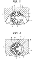
- a housing 1 has a through hole 1a in which a slide bar 4 is axially slidably inserted. At a distal end of the slide bar 4 is formed in an axial direction a deep hole 4a which is open at the distal end face of the slide bar. An open mouth of the hole 4a is closed with a detachable plug body 9 fixed by means of a bolt 10 or the like to form a cylindrical filter chamber 7.
- One of the opposite side walls of the housing 1 is provided with an inlet 2 through which the molten resin flows in, while the other side wall is provided with an outlet 3 through which the molten resin flows out.
- a communicating hole 6 in a form of an elongated bore or a round bore, etc. extending in an axial direction at a position corresponding to the outlet 3 of the housing 1.
- An interior of the filter chamber 7 communicates with the outlet 3 through the communicating hole 6.
- a concave 5 having a constant depth is formed in a wide range on an outer peripheral wall of the cylindrical filter chamber 7 except an area adjacent to the communicating hole 6. The concave 5 communicates with the inlet 2 of the housing 1 at almost the middle portion thereof.
- a plurality of fitting holes 11 which extend from the peripheral wall toward an axis core of the filter chamber 7 and are spaced in both circumferential and axial directions with respect to one another.
- a screen cartridge 8 is detachably inserted into each of the fitting holes 11 as described below.
- a larger number of the fitting holes 11 can be provided in case where they are arranged in an axially staggered relation.
- the screen cartridge 8 includes a breaker plate 15 of a perforated plate in a form of a bottomed conical tube which decreases in diameter from its open end toward a bottom end, and a net member 16 in a form of a bottomed conical tube which decreases in diameter from its open end toward a bottom end.
- the breaker plate 15 in a form of a bottomed conical tube has a flange portion 15b projecting from an outer circumferential edge of its open end.
- An entire area except the flange portion 15b is in a form of a perforated plate having a plurality of perforations 15a which are spaced with respect to one another and extend through the breaker plate from an outer peripheral face toward an inner peripheral face thereof.
- a groove 15c At an inner peripheral face of the flange portion 15b is formed a groove 15c into which a smaller holding ring 13 is fitted.
- the breaker plate 15 can be detachably fitted by inserting it into each of the fitting holes 11 formed in the concave 5 of the slide bar 4, in a state where a rear face of each the flange portion 15b abuts to a projection 11a formed at an inner peripheral face of the fitting hole 11, and then engaging a larger holding ring 12 in a groove 14 formed at the inner peripheral face of the fitting hole 11.
- the breaker plate 15 can be easily extracted from the fitting hole 11.
- the net member 16 in a form of a bottomed conical tube inserted into the breaker plate 15 can be detachably fitted by engaging the smaller holding ring 13 in the groove 15c formed at the inner peripheral face of the breaker plate 15, and can be easily extracted from the breaker plate 15 by removing the smaller holding ring 13.
- the molten resin which has entered through the inlet 2 flows into each of the screen cartridges 8 by way of a flat passage constituted by a gap between an inner peripheral face of the through hole 1a of the housing 1 and the outer peripheral face of the concave 5 of the slide bar 4.
- the molten resin flows into the filter chamber 7 and then flows out through the outlet 3 by way of the communicating hole 6.
- the screen cartridge 8 When the filtered foreign objects have been accumulated inside the net member 16 with a lapse of the filtering time and the pressure loss has become over the determined value, the screen cartridge 8 will be exchanged.
- the slide bar 4 is linearly translated in a direction of a hollow arrow in Fig. 1 by means of linear actuating means such as a hydraulic cylinder or the like which is not shown, in order to project the whole filter chamber 7 from the one end of the through hole 1a of the housing 1.
- linear actuating means such as a hydraulic cylinder or the like which is not shown
- the net member 16 is detachably inserted in the breaker plate 15 in this embodiment, it is possible to exchange only the net member 16 with a new one.
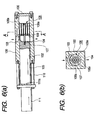
- the screen exchanging device includes a housing 21 provided with two through holes 21a, 21b which are formed therein in parallel, an inlet 22 bifurcated in two branch inlets 22a, 22b, one of the branch inlet 22a communicating with one of the through holes 21a and the other branch inlet 22b communicating with the other through hole 21b, and an outlet 23 bifurcated in two branch outlets 23a, 23b, one of the branch outlet 23a communicating with one of the through holes 21a and the other branch outlet 23b communicating with the other through hole 21b.
- a slide bar 4 which is similar to the one illustrated in Figs. 1 to 4.
- the screen exchanging device in this embodiment is similar to the one described referring to Figs. 1 to 4, and therefore, denoting them with the same reference numerals, a further explanation will be omitted.
- the exchanging operation of the screen cartridges 8 can be conducted alternately.
- the screen cartridge may not necessarily include the breaker plate 15 of the type in which the net member 16 is detachably inserted as described above, but it can be changed to a breaker plate integrally provided with a net member.
Landscapes
- Chemical & Material Sciences (AREA)
- Chemical Kinetics & Catalysis (AREA)
- Engineering & Computer Science (AREA)
- Mechanical Engineering (AREA)
- Extrusion Moulding Of Plastics Or The Like (AREA)
- Filtration Of Liquid (AREA)
- Injection Moulding Of Plastics Or The Like (AREA)
Applications Claiming Priority (2)
| Application Number | Priority Date | Filing Date | Title |
|---|---|---|---|
| JP34243098A JP3827868B2 (ja) | 1998-12-02 | 1998-12-02 | スクリーン交換装置 |
| JP34243098 | 1998-12-02 |
Publications (1)
| Publication Number | Publication Date |
|---|---|
| EP1005973A1 true EP1005973A1 (de) | 2000-06-07 |
Family
ID=18353684
Family Applications (1)
| Application Number | Title | Priority Date | Filing Date |
|---|---|---|---|
| EP99123782A Withdrawn EP1005973A1 (de) | 1998-12-02 | 1999-11-30 | Filterwechselvorrichtung |
Country Status (3)
| Country | Link |
|---|---|
| US (1) | US6261079B1 (de) |
| EP (1) | EP1005973A1 (de) |
| JP (1) | JP3827868B2 (de) |
Cited By (1)
| Publication number | Priority date | Publication date | Assignee | Title |
|---|---|---|---|---|
| CN111408184A (zh) * | 2020-03-30 | 2020-07-14 | 吕梁学院 | 一种水污染控制用过滤装置的滤板更换机构 |
Families Citing this family (10)
| Publication number | Priority date | Publication date | Assignee | Title |
|---|---|---|---|---|
| JP2005125184A (ja) * | 2003-10-22 | 2005-05-19 | Gpc Tsuchiya:Kk | 流体用スクリーンチェンジャ |
| KR100571149B1 (ko) * | 2003-11-12 | 2006-04-17 | 엘에스전선 주식회사 | 압출기의 원형 슬릿타입 브레이커 플레이트 어셈블리 |
| JP5156349B2 (ja) * | 2007-11-22 | 2013-03-06 | 旭化成ケミカルズ株式会社 | ブロック共重合体又はその水添物のペレットの製造方法 |
| JP5156348B2 (ja) * | 2007-11-22 | 2013-03-06 | 旭化成ケミカルズ株式会社 | ブロック共重合体又はその水添物ペレットの製造方法 |
| CN103692636B (zh) * | 2013-11-12 | 2015-12-09 | 张家港市紫东机械科技有限公司 | 一种无丝网过滤器 |
| CN104760152B (zh) * | 2015-03-12 | 2017-10-31 | 广东仕诚塑料机械有限公司 | 一种筛网过滤器 |
| CN105522711B (zh) | 2016-01-20 | 2017-11-10 | 施晓荷 | 连续换网器及换网装置和挤出机 |
| EP3308940B1 (de) * | 2016-10-17 | 2025-03-05 | Next Generation Analytics GmbH | Filtersystem für viskose oder hochviskose flüssigkeiten, insbesondere kunststoffschmelzen und verfahren zur filtration von viskosen oder hochviskosen flüssigkeiten |
| US11260570B2 (en) * | 2018-05-07 | 2022-03-01 | PSI-Polymer Systems, Inc. | Filtration apparatuses and screen changer devices for polymer processing and related methods |
| CN111497174B (zh) * | 2020-04-19 | 2022-01-11 | 广西膜宝包科技发展有限公司 | 一种塑料吹塑自动换网结构的工作方法及其对接装置 |
Citations (5)
| Publication number | Priority date | Publication date | Assignee | Title |
|---|---|---|---|---|
| US2763374A (en) * | 1952-07-02 | 1956-09-18 | Reed Prentice Corp | Apparatus for screening plastic materials |
| DE2947698A1 (de) * | 1979-11-27 | 1981-06-04 | Hermann Berstorff Maschinenbau Gmbh, 3000 Hannover | Siebwechselvorrichtung fuer thermoplastische formmassen verarbeitende schneckenstrangpressen |
| JPS6036122A (ja) * | 1983-08-10 | 1985-02-25 | Japan Steel Works Ltd:The | 広濾過面積スクリンチエンジヤ− |
| US5125823A (en) * | 1990-04-19 | 1992-06-30 | Kreyenborg Verwaltungen Und Beteiligungen Kg | Apparatus for filtering plasticized materials |
| US5449458A (en) * | 1992-04-21 | 1995-09-12 | Gneuss Kunststofftechnik Gmbh | Filter system for molten plastic |
Family Cites Families (5)
| Publication number | Priority date | Publication date | Assignee | Title |
|---|---|---|---|---|
| NL7905055A (nl) * | 1979-06-29 | 1980-12-31 | Akzo Nv | Voor vloeistof alsmede spingarnituur voorzien van een dergelijke filter. |
| DE2947685A1 (de) * | 1979-11-27 | 1981-07-23 | Hermann Berstorff Maschinenbau Gmbh, 3000 Hannover | Filtervorrichtung fuer schneckenextruder |
| US4453905A (en) * | 1983-06-01 | 1984-06-12 | Bennett Bobby B | Plastics recycling apparatus |
| DE3935667A1 (de) * | 1989-10-26 | 1991-05-02 | Ewikon Heizkanalsysteme Gmbh & | Elektrisch aufheizbare duese fuer eine spritzgiessmaschine, eine heisskanaleinrichtung o.dgl. |
| JP3171752B2 (ja) | 1994-05-06 | 2001-06-04 | 株式会社日本製鋼所 | 可塑性材料濾過装置 |
-
1998
- 1998-12-02 JP JP34243098A patent/JP3827868B2/ja not_active Expired - Fee Related
-
1999
- 1999-11-30 EP EP99123782A patent/EP1005973A1/de not_active Withdrawn
- 1999-12-01 US US09/451,764 patent/US6261079B1/en not_active Expired - Fee Related
Patent Citations (5)
| Publication number | Priority date | Publication date | Assignee | Title |
|---|---|---|---|---|
| US2763374A (en) * | 1952-07-02 | 1956-09-18 | Reed Prentice Corp | Apparatus for screening plastic materials |
| DE2947698A1 (de) * | 1979-11-27 | 1981-06-04 | Hermann Berstorff Maschinenbau Gmbh, 3000 Hannover | Siebwechselvorrichtung fuer thermoplastische formmassen verarbeitende schneckenstrangpressen |
| JPS6036122A (ja) * | 1983-08-10 | 1985-02-25 | Japan Steel Works Ltd:The | 広濾過面積スクリンチエンジヤ− |
| US5125823A (en) * | 1990-04-19 | 1992-06-30 | Kreyenborg Verwaltungen Und Beteiligungen Kg | Apparatus for filtering plasticized materials |
| US5449458A (en) * | 1992-04-21 | 1995-09-12 | Gneuss Kunststofftechnik Gmbh | Filter system for molten plastic |
Non-Patent Citations (1)
| Title |
|---|
| PATENT ABSTRACTS OF JAPAN vol. 009, no. 162 (M - 394) 6 July 1985 (1985-07-06) * |
Cited By (1)
| Publication number | Priority date | Publication date | Assignee | Title |
|---|---|---|---|---|
| CN111408184A (zh) * | 2020-03-30 | 2020-07-14 | 吕梁学院 | 一种水污染控制用过滤装置的滤板更换机构 |
Also Published As
| Publication number | Publication date |
|---|---|
| JP3827868B2 (ja) | 2006-09-27 |
| US6261079B1 (en) | 2001-07-17 |
| JP2000167907A (ja) | 2000-06-20 |
Similar Documents
| Publication | Publication Date | Title |
|---|---|---|
| US6261079B1 (en) | Screen exchanging device | |
| DE69130393T2 (de) | Modulare, mikroporöse filteranlagen | |
| US4434053A (en) | Two-stage filter for injection molding machine | |
| US20020125188A1 (en) | Liquid filter having interchangeable spin-on canister filter and cartridge filter, and methods | |
| US20080060992A1 (en) | Filter device | |
| MXPA96006189A (en) | Filter of a | |
| DE69617501T2 (de) | Flüssigkeitsfilter | |
| DE202011000268U1 (de) | Rückspülfilter mit Spüleinrichtung | |
| JP2010253473A (ja) | 樹脂溶融体用フィルタ装置 | |
| JPH03208619A (ja) | 円筒形スクリーンパックを備えたスクリーンパック交換装置及びその操作方法 | |
| DE10012461A1 (de) | Flüssigkeitsfilter, insbesondere Ölfilter | |
| USRE37681E1 (en) | Filter member and screen changer for use in resin extruder | |
| CA2153737A1 (en) | Rebuildable spin-on filters | |
| EP0943796B1 (de) | Flüssigkeitsfilter zum Reinigen von Kraftstoff | |
| US5046936A (en) | Draw plate for the production of membranes of an organic material | |
| US20040007541A1 (en) | Integrated liquid and gas distribution device for underdrain block laterals | |
| US3405805A (en) | Filter | |
| EP2221095A1 (de) | Filtereinrichtung zur Filtration von Fluid | |
| EP1093840A2 (de) | Flüssigkeitsfilter mit Filterumgehungsventil | |
| EP0062086B1 (de) | Vorrichtung zur Behandlung von Flüssigkeiten | |
| US3984325A (en) | Filter device | |
| US20230149837A1 (en) | Filter cartridge, and method of retrofitting filter housing | |
| US4337790A (en) | Filtering device | |
| CA2444070C (en) | Testing device for ultrasonic inspection of barstock | |
| WO2006057805A2 (en) | Cartridge filter system with lift tube |
Legal Events
| Date | Code | Title | Description |
|---|---|---|---|
| PUAI | Public reference made under article 153(3) epc to a published international application that has entered the european phase |
Free format text: ORIGINAL CODE: 0009012 |
|
| AK | Designated contracting states |
Kind code of ref document: A1 Designated state(s): AT BE CH CY DE DK ES FI FR GB GR IE IT LI LU MC NL PT SE |
|
| AX | Request for extension of the european patent |
Free format text: AL;LT;LV;MK;RO;SI |
|
| 17P | Request for examination filed |
Effective date: 20000711 |
|
| AKX | Designation fees paid |
Free format text: DE IT |
|
| 17Q | First examination report despatched |
Effective date: 20020114 |
|
| GRAP | Despatch of communication of intention to grant a patent |
Free format text: ORIGINAL CODE: EPIDOSNIGR1 |
|
| STAA | Information on the status of an ep patent application or granted ep patent |
Free format text: STATUS: THE APPLICATION IS DEEMED TO BE WITHDRAWN |
|
| 18D | Application deemed to be withdrawn |
Effective date: 20040330 |