EP1005993A2 - Flüssigkeitsausstosskopf und Flüssigkeitsausstossgerät - Google Patents
Flüssigkeitsausstosskopf und Flüssigkeitsausstossgerät Download PDFInfo
- Publication number
- EP1005993A2 EP1005993A2 EP99309714A EP99309714A EP1005993A2 EP 1005993 A2 EP1005993 A2 EP 1005993A2 EP 99309714 A EP99309714 A EP 99309714A EP 99309714 A EP99309714 A EP 99309714A EP 1005993 A2 EP1005993 A2 EP 1005993A2
- Authority
- EP
- European Patent Office
- Prior art keywords
- liquid
- movable
- bubble
- element substrate
- liquid discharge
- Prior art date
- Legal status (The legal status is an assumption and is not a legal conclusion. Google has not performed a legal analysis and makes no representation as to the accuracy of the status listed.)
- Granted
Links
- 239000007788 liquid Substances 0.000 title claims abstract description 118
- 239000000758 substrate Substances 0.000 claims abstract description 40
- 238000007599 discharging Methods 0.000 claims description 8
- 229910052581 Si3N4 Inorganic materials 0.000 claims description 5
- HQVNEWCFYHHQES-UHFFFAOYSA-N silicon nitride Chemical compound N12[Si]34N5[Si]62N3[Si]51N64 HQVNEWCFYHHQES-UHFFFAOYSA-N 0.000 claims description 5
- 239000006185 dispersion Substances 0.000 claims description 4
- 230000000694 effects Effects 0.000 claims description 3
- 238000000034 method Methods 0.000 description 15
- 239000000463 material Substances 0.000 description 8
- 239000010408 film Substances 0.000 description 6
- 238000010276 construction Methods 0.000 description 5
- 239000004033 plastic Substances 0.000 description 5
- 229920003023 plastic Polymers 0.000 description 5
- 238000004458 analytical method Methods 0.000 description 4
- 229910052751 metal Inorganic materials 0.000 description 4
- 239000002184 metal Substances 0.000 description 4
- 238000001454 recorded image Methods 0.000 description 4
- 238000011144 upstream manufacturing Methods 0.000 description 4
- VYPSYNLAJGMNEJ-UHFFFAOYSA-N Silicium dioxide Chemical compound O=[Si]=O VYPSYNLAJGMNEJ-UHFFFAOYSA-N 0.000 description 3
- XUIMIQQOPSSXEZ-UHFFFAOYSA-N Silicon Chemical compound [Si] XUIMIQQOPSSXEZ-UHFFFAOYSA-N 0.000 description 3
- 230000008859 change Effects 0.000 description 3
- 238000005530 etching Methods 0.000 description 3
- 239000004744 fabric Substances 0.000 description 3
- 239000010985 leather Substances 0.000 description 3
- 230000004048 modification Effects 0.000 description 3
- 238000012986 modification Methods 0.000 description 3
- 229910052710 silicon Inorganic materials 0.000 description 3
- 239000010703 silicon Substances 0.000 description 3
- 229910052814 silicon oxide Inorganic materials 0.000 description 3
- 239000002210 silicon-based material Substances 0.000 description 3
- PXHVJJICTQNCMI-UHFFFAOYSA-N Nickel Chemical compound [Ni] PXHVJJICTQNCMI-UHFFFAOYSA-N 0.000 description 2
- 238000009835 boiling Methods 0.000 description 2
- 239000000919 ceramic Substances 0.000 description 2
- 238000010586 diagram Methods 0.000 description 2
- 238000006073 displacement reaction Methods 0.000 description 2
- 150000002739 metals Chemical class 0.000 description 2
- 230000008569 process Effects 0.000 description 2
- 239000004753 textile Substances 0.000 description 2
- 235000017166 Bambusa arundinacea Nutrition 0.000 description 1
- 235000017491 Bambusa tulda Nutrition 0.000 description 1
- 241001330002 Bambuseae Species 0.000 description 1
- RYGMFSIKBFXOCR-UHFFFAOYSA-N Copper Chemical compound [Cu] RYGMFSIKBFXOCR-UHFFFAOYSA-N 0.000 description 1
- 235000015334 Phyllostachys viridis Nutrition 0.000 description 1
- 229910004200 TaSiN Inorganic materials 0.000 description 1
- 238000009825 accumulation Methods 0.000 description 1
- 230000009471 action Effects 0.000 description 1
- 229910052782 aluminium Inorganic materials 0.000 description 1
- XAGFODPZIPBFFR-UHFFFAOYSA-N aluminium Chemical compound [Al] XAGFODPZIPBFFR-UHFFFAOYSA-N 0.000 description 1
- 230000003466 anti-cipated effect Effects 0.000 description 1
- 239000011425 bamboo Substances 0.000 description 1
- 230000015572 biosynthetic process Effects 0.000 description 1
- 230000005587 bubbling Effects 0.000 description 1
- 229910010293 ceramic material Inorganic materials 0.000 description 1
- 230000002301 combined effect Effects 0.000 description 1
- 238000004891 communication Methods 0.000 description 1
- 238000007796 conventional method Methods 0.000 description 1
- 229910052802 copper Inorganic materials 0.000 description 1
- 239000010949 copper Substances 0.000 description 1
- 238000005034 decoration Methods 0.000 description 1
- 239000000835 fiber Substances 0.000 description 1
- 210000004907 gland Anatomy 0.000 description 1
- 239000011521 glass Substances 0.000 description 1
- 238000009413 insulation Methods 0.000 description 1
- 239000002649 leather substitute Substances 0.000 description 1
- 230000007774 longterm Effects 0.000 description 1
- 238000004519 manufacturing process Methods 0.000 description 1
- 230000007246 mechanism Effects 0.000 description 1
- 229910052759 nickel Inorganic materials 0.000 description 1
- 238000005457 optimization Methods 0.000 description 1
- 230000002093 peripheral effect Effects 0.000 description 1
- 238000000206 photolithography Methods 0.000 description 1
- 239000011120 plywood Substances 0.000 description 1
- 238000012545 processing Methods 0.000 description 1
- 230000001681 protective effect Effects 0.000 description 1
- 230000004044 response Effects 0.000 description 1
- 230000000630 rising effect Effects 0.000 description 1
- 239000004065 semiconductor Substances 0.000 description 1
- 239000010409 thin film Substances 0.000 description 1
- 239000002023 wood Substances 0.000 description 1
Images


Classifications
-
- B—PERFORMING OPERATIONS; TRANSPORTING
- B41—PRINTING; LINING MACHINES; TYPEWRITERS; STAMPS
- B41J—TYPEWRITERS; SELECTIVE PRINTING MECHANISMS, i.e. MECHANISMS PRINTING OTHERWISE THAN FROM A FORME; CORRECTION OF TYPOGRAPHICAL ERRORS
- B41J2/00—Typewriters or selective printing mechanisms characterised by the printing or marking process for which they are designed
- B41J2/005—Typewriters or selective printing mechanisms characterised by the printing or marking process for which they are designed characterised by bringing liquid or particles selectively into contact with a printing material
- B41J2/01—Ink jet
- B41J2/135—Nozzles
- B41J2/14—Structure thereof only for on-demand ink jet heads
- B41J2/14016—Structure of bubble jet print heads
- B41J2/14032—Structure of the pressure chamber
- B41J2/14056—Plural heating elements per ink chamber
-
- B—PERFORMING OPERATIONS; TRANSPORTING
- B41—PRINTING; LINING MACHINES; TYPEWRITERS; STAMPS
- B41J—TYPEWRITERS; SELECTIVE PRINTING MECHANISMS, i.e. MECHANISMS PRINTING OTHERWISE THAN FROM A FORME; CORRECTION OF TYPOGRAPHICAL ERRORS
- B41J2/00—Typewriters or selective printing mechanisms characterised by the printing or marking process for which they are designed
- B41J2/005—Typewriters or selective printing mechanisms characterised by the printing or marking process for which they are designed characterised by bringing liquid or particles selectively into contact with a printing material
- B41J2/01—Ink jet
- B41J2/135—Nozzles
- B41J2/14—Structure thereof only for on-demand ink jet heads
- B41J2/14016—Structure of bubble jet print heads
- B41J2/14032—Structure of the pressure chamber
- B41J2/14048—Movable member in the chamber
-
- B—PERFORMING OPERATIONS; TRANSPORTING
- B41—PRINTING; LINING MACHINES; TYPEWRITERS; STAMPS
- B41J—TYPEWRITERS; SELECTIVE PRINTING MECHANISMS, i.e. MECHANISMS PRINTING OTHERWISE THAN FROM A FORME; CORRECTION OF TYPOGRAPHICAL ERRORS
- B41J2/00—Typewriters or selective printing mechanisms characterised by the printing or marking process for which they are designed
- B41J2/005—Typewriters or selective printing mechanisms characterised by the printing or marking process for which they are designed characterised by bringing liquid or particles selectively into contact with a printing material
- B41J2/01—Ink jet
- B41J2/135—Nozzles
- B41J2/14—Structure thereof only for on-demand ink jet heads
- B41J2/14016—Structure of bubble jet print heads
- B41J2/14072—Electrical connections, e.g. details on electrodes, connecting the chip to the outside...
Definitions
- This invention can be applied to apparatuses such as a printer, a copying machine, a facsimile apparatus such as a communication system and a word processor having a printer portion for effecting recording on a recording medium such as paper, yarn, fiber, cloth, metals, plastics, glass, wood or ceramics, and further an industrial recording apparatus compositely combined with various processing apparatuses.
- apparatuses such as a printer, a copying machine, a facsimile apparatus such as a communication system and a word processor having a printer portion for effecting recording on a recording medium such as paper, yarn, fiber, cloth, metals, plastics, glass, wood or ceramics, and further an industrial recording apparatus compositely combined with various processing apparatuses.
- recording in the present invention means not only imparting meaningful images such as characters and figures to a recording medium, but also imparting meaningless images such as patterns to a recording medium.
- an ink jet recording method i.e., a so-called bubble jet recording method, of imparting energy such as heat to ink to thereby cause a state change resolution from a steep volume change (creation of a bubble) to the ink, discharging the ink from a discharge port by an acting force based on this state change of the ink, and causing the ink to adhere to a recording medium to thereby effect image formation.
- a recording apparatus using this bubble jet recording method as disclosed in U.S. Patent No.
- this bubble jet recording method has come to be utilized in many office machines such as printers, copying machines and facsimile apparatuses, and further in an industrial system such as a textile printing apparatus.
- Figs. 9A and 9B of the accompanying drawings are a top plan view and a cross-sectional view, respectively, of the essential portions of a liquid discharge head according to the prior art.
- a movable member 106 supported on and fixed to an element substrate 100 by a fixing portion 106d is formed so that the free end 106b of a movable portion 106c may be displaced in the direction of arrow A with a root 106a as a fulcrum.
- the upper surface side of the movable member 106 is a liquid flow path which is the flow path of ink, and arrow B indicates the direction in which the ink flows.
- a heat generating member 102 is formed generating energy for creating a bubble in the ink, and the bubble is created on the upper surface of the heat generating member 102. By this bubble, the free end 106b of the movable member 100 is displaced upwardly and the ink is discharged from a discharge port, not shown.
- the present invention has as its main task to basically enhance the fundamental discharge characteristic of a conventional method of forming a bubble, particularly, a bubble resulting from film boiling, in a liquid flow path to thereby discharge liquid to a level which could heretofore not be anticipated.
- the present invention has as its object to provide a liquid discharge head for discharging liquid by the utilization of the displacement of the free end of a movable member by pressure based on the creation of a bubble, which is improved in the durability of the movable member and is stable in discharge characteristic and high in reliability, and a liquid discharge apparatus.
- An aspect of the present invention provides a liquid discharge head having an element substrate on the surface of which are provided in parallel a plurality of discharge energy generating elements generating heat energy for creating a bubble in liquid, a fixed portion provided on said element substrate so as to face said plurality of discharge energy generating elements, and fixed to said element substrate, and a plurality of movable members comprising a movable portion extending from the end portion of said fixed portion and displaced by said bubble, wherein a fulcrum about which said movable portion is displaced is located on said movable portion other than a corner portion formed at the boundary between said movable portion and said fixed portion.
- the fulcrum of the movable portion is formed on the other portion than the corner portions. Thereby, the concentration of stress to the corner portions is avoided.
- the plurality of movable members may be of a construction in which they are connected together at the position of the fulcrum, and the movable members may be formed of silicon nitride.
- the liquid discharge head of the present invention is a liquid discharge head having an element substrate on the surface of which are provided in parallel a plurality of discharge energy generating elements generating heat energy for creating a bubble in liquid, a fixed portion provided on said element substrate so as to face said plurality of discharge energy generating elements, and fixed to said element substrate, and a plurality of movable members comprising a movable portion extending from the end portion of said fixed portion and displaced by said bubble, characterized in that the shape of the fixed portion is a shape which expedites stress dispersion for preventing stress from concentrating on particular one of the movable members.
- the liquid discharge apparatus of the present invention has a carriage removably holding the liquid discharge head of the present invention thereon, and supported for reciprocal movement along the surface of a recording medium, and discharges liquid from the liquid discharge head of a head cartridge to thereby effect recording on the recording medium.
- Fig. 1 is a cross-sectional view along the direction of a liquid flow path for illustrating the basic structure of a liquid discharge head according to an embodiment of the present invention.
- Figs. 2A and 2B are a top plan view and a cross-sectional view, respectively, of the essential portions of the liquid discharge head of the present invention.
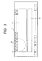
- Fig. 3 is a plan view of an element substrate shown in Fig. 1.
- Fig. 4 is an enlarged view of the portion IV of Fig. 3.
- Fig. 5 is an enlarged view showing a modification of the element substrate shown in Fig. 1.
- Figs. 6A, 6B and 6C are seen-through views showing a fixed portion applicable to the present invention.
- Fig. 7 is a perspective view showing a liquid discharge apparatus carrying the liquid discharge head of the present invention thereon.
- Fig. 8 is a block diagram of the whole of an apparatus for operating an ink discharge recording apparatus to which the liquid discharge head of the present invention is applied.
- Figs. 9A and 9B are a top plan view and a cross-sectional view, respectively, of the essential portions of a liquid discharge head according to the prior art.
- Fig. 1 is a cross-sectional view along the direction of a liquid flow path for illustrating the basic structure of an embodiment of the liquid discharge head of the present invention.
- this liquid discharge head has an element substrate 1 on which are provided in parallel a plurality of heat generating members 2 (in Fig. 1, only one is shown) giving heat energy for creating a bubble in liquid, a top plate 3 joined onto the element substrate 1, and an orifice plate 4 joined to the front end surfaces of the element substrate 1 and the top plate 3.
- the element substrate 1 has silicon oxide film or silicon nitride film directed to insulation and heat accumulation formed on a substrate of silicon or the like, and an electrical resistance layer and a wiring electrode constituting the heat generating members 2 and patterned thereon. A voltage is applied from the wiring electrode to the electrical resistance layer and an electric current is flowed to the electrical resistance layer, whereby the heat generating members 2 generate heat.
- the top plate 3 is for constituting a plurality of liquid flow paths 7 corresponding to the heat generating members 2 and a common liquid chamber 8 for supplying liquid to the liquid flow paths 7, and flow path side walls 9 extending from a ceiling portion to among the heat generating members 2 are provided integrally therewith.
- the top plate 3 is formed of a silicon material, and the pattern of the liquid flow paths 7 and the common liquid chamber 9 can be formed by etching, or can be formed by etching the portions of the liquid flow paths 7 after the material of the flow path side walls 9 such as silicon nitride or silicon oxide has been accumulated on the silicon substrate by a known film forming method such as CVD.
- the orifice plate 4 is formed with a plurality of discharge ports 5 corresponding to the liquid flow paths 7 and communicating with the common liquid chamber 8 through the liquid flow paths 7, respectively.
- the orifice plate 4 is also formed of a silicon material, and is formed by shaving the silicon substrate formed with the discharge ports 5 to a thickness of the order of 10 to 150 ⁇ m.
- the orifice plate 4 is not always a construction necessary to the present invention, but instead of providing the orifice plate 4, when the liquid flow paths 7 are to be formed in the top plate 3, a wall corresponding to the thickness of the orifice plate 4 is left on the fore end surface of the top plate 3, and the discharge ports 5 are formed in this portion, whereby there can be provided a top plate with discharge ports.
- this liquid discharge head is provided with a cantilever-like movable member 6 disposed in face-to-face relationship with the heat generating members and directly fixed to the element substrate 1.
- the movable member 6 is thin film formed of a silicon material such as silicon nitride or silicon oxide, or nickel or the like excellent in resiliency.
- This movable member 6 is supported on and fixed to the element substrate 1 by a fixing portion 6a on the upstream side of a great flow flowing from the common liquid chamber 8 to the discharge ports 5 side via above the movable member 6, and is formed with a root 6a which provides a fulcrum when the free end 6b of a movable portion 6c is displaced. Further, so as to have the free end 6b at the downstream side with respect to this root 6a, the free end 6b is located at a position facing the heat generating member 2 and near the center of the heat generating member 2 and is disposed at a predetermined distance from the heat generating member 2. The space between the heat generating member 2 and the movable member 6 provides a bubble creating area 10.
- the heat generating member 2 When on the basis of the above-described construction, the heat generating member 2 is caused to generate heat, the heat acts on the liquid in the bubble creating area 10 between the movable member 6 and the heat generating member 2, whereby a bubble based on the film boiling phenomenon is created on the heat generating member 2 and grows. Pressure resulting from the growth of this bubble preferentially acts on the movable member 6, and the free end 6b of the movable member 6, as indicated by broken line in Fig. 1, is displaced so as to greatly open toward the discharge ports 5 side about the root 6a.
- the propagation of the pressure based on the creation of the bubble or the growth of the bubble itself is directed to the discharge ports 5 side and the liquid is discharged from the discharge ports 5.
- the movable member 6 having the root 6a at the upstream side (the common liquid chamber 8 side) of the flow of the liquid in the liquid flow paths 7 and having the free end 6b at the downstream side (the discharge ports 5 side) is provided on the bubble creating area 10, whereby the direction of propagation of the pressure of the bubble is directed toward the downstream side and thus, the pressure of the bubble directly and efficiently contributes to the discharge of the liquid.
- the direction of growth of the bubble itself like the direction of propagation of the pressure, is directed toward the downstream side, and the bubble grows more greatly at the downstream side than at the upstream side.
- the bubble when the bubble enters its disappearing process, the bubble rapidly disappears due to the combined effect thereof with the resilient force of the movable member 6, and the movable member 6 also finally returns to its initial position indicated by solid line in Fig. 1.
- the liquid flows in from the upstream side, i.e., the common liquid chamber 8 side and the refilling of the liquid flow paths 7 with the liquid is effected, and this refilling with the liquid is effected efficiently, reasonably and stably with the returning action of the movable member 6.
- Figs. 2A and 2B are a top plan view and a cross-sectional view, respectively, of the essential portions of the liquid discharge head shown in Fig. 1.
- the movable member 6 formed on the element substrate 1 is fixed by the fixed portion 6d via the manufacturing steps of a semiconductor device such as photolithography and etching, and the tip end portions of the movable portions facing respective ones of the heat generating members 2 provide the free ends 6b.
- the roots 6a are formed not on a line C indicating the end portion of the fixed portion 6d, but on the position of a line D.
- the fulcrum of the movable members 6 is not the end portion of the fixed portion 6d, but the roots 6a.
- the concentration of stress to a corner portion 6e when the free ends 6b are displaced is avoided.
- the roots 6a which provide the fulcrum are formed on the position of the line D, whereby the roots 6a are made common to adjacent movable portions 6c, whereby the dispersion of stress is done.
- the increased strength of the movable members 6 with respect to torsion can be achieved and the durability thereof can be remarkably improved.
- the movable members 6 are stably displaced even during the long-term use thereof and therefore, there can be obtained a liquid discharge head which is stable in discharge characteristics and high in reliability.
- Fig. 3 is a plan view showing the element substrate 1 shown in Fig. 1.
- a plurality of heat generating members 2 are disposed in parallel along one edge portion of the element substrate 1 on that surface of the element substrate 1 which is adjacent to the top plate 3.
- the central portion of that surface of the element substrate 1 is a heater driver forming area 21, and a plurality of heater drivers arranged in the same direction as the direction of arrangement of the plurality of heat generating members 2 are formed in the heater driver forming area 21.
- a shift register latch 22 is formed on that portion of the heater driver forming area 21 which is opposite to the heat generating members 2.
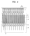
- Fig. 4 is an enlarged view of the portion IV of Fig. 3.
- the element substrate 1 used in the present embodiment use is made of one of high density heater arrangement in which the resolution of a recorded image is 600 dpi (dots per inch) or greater.
- a row of heater drivers for driving the heat generating members 2 form one stage.
- the heater driver forming area 21 shown in Fig. 3 there are formed heater drivers 31 arranged in the same direction as the direction of arrangement of the heat generating members 2, as shown in Fig. 4.
- the pitch of the heater drivers 31 is the same as the pitch of the heat generating members 2, and the pitch P 1 thereof is 15 to 42 ⁇ m.
- the heater drivers 31 are comprised of sources 32 extending in a direction perpendicular to the direction of arrangement of the heater drivers 31, drains 33 and gates 34 parallel to the sources 32.
- the drains 33 are electrically connected to the heat generating members 2.
- a heater driving power source 35 constituted by a metallic layer and a gland 36 are formed in the heater driver forming area 21.
- the condition of the heater drivers 31 is a high withstand voltage dielectric strength (of the order of 10 to 50 V) and as previously described, drivers which can be disposed at a very narrow width of a pitch of 15 to 42 ⁇ m are necessary.
- the heater drivers 31 satisfying that condition use can be made of offset MOS type, LDMOS type or VDMOS type transistors or the like.
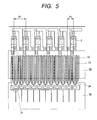
- Fig. 5 is an enlarged view showing a modification of the element substrate 1 shown in Fig. 1. While in the embodiment shown in Fig. 4, the pitch of the heater drivers 31 is the same as the pitch of the heat generating members 2, in the modification shown in Fig. 5, the pitch P 3 of the heater drivers 31 is double the pitch P 2 of the heat generating members 2.
- a plurality of heat generating members 2 are disposed in a nozzle and the plurality of heat generating members 2 are driven by a nozzle, whereby harmony recording ca be effected.
- the heat generating members 2 are arranged so that the resolution of a recorded image may be 1200 dpi.
- the voltage of the power source for driving the heat generating members 2 was 24 V.
- the pitch of the heat generating members 2 was about 21 ⁇ m, and the width of the heat generating members 2 was 14 um including the margin thereof.
- the length of the heat generating members 2 was 60 ⁇ m.
- the resistance value of the heat generating members 2 it is necessary to make the resistance value of the heat generating members 2 great, and 50 ⁇ / ⁇ or greater is required as the sheet resistance value of the heat generating members 2.
- TaSiN was used as the material of the heat generating members 2 for 1200 dpi, whereby the resistance value of the heat generating members 2 was set to 200 ⁇ or greater.
- the heater drivers 31 use was made of LDMOS type transistors of which the width could be made relatively small.
- the heater drives 31 can be disposed highly densely in a row (a stage) on the element substrate 1 and the efficient layout of the wiring becomes possible by the element substrate 1.
- the element substrate 1 can be downsized to a chip size.
- the heat generating members 2 using a material having sheet resistance as high as 50 ⁇ / ⁇ or greater and the heater drivers 31 of high withstand pressure such as MOS of the above-mentioned kind capable of withstanding a voltage of 10 V or greater being combined together, there can be realized the construction of a liquid discharge head in which the irregularity of the voltage applied to the heat generating members 2 is small.
- the movable member adopted in the liquid discharge head of the present invention in its state as indicated by broken line in Fig. 1, can achieve the increased strength of the fulcrum when it is greatly flexed with the bubble created by the movable member.
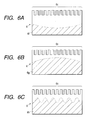
- Figs. 6A to 6C show upper surface seen-through views of fixed portions 6f to 6h applicable to the present invention.
- the end surface of the fixed portion 6d shown in Figs. 2A and 2B which is adjacent to the corner portion 6e is straight, whereas said end surface may be of a concave shape as shown in Fig. 6A, or a convex shape as shown in Fig. 6B, or a wavy shape as shown in Fig. 6C.
- the end surface being made into a curved shape shown in any of Figs. 6A to 6C, the stress to the movable portion 6c is widely dispersed. Thereby, the stress is prevented from concentrating into the particular movable portion 6c.
- any other shape than the shapes shown in Figs. 6A to 6C may be adopted if the concentration of the stress to the particular movable portion 6c is prevented.
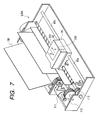
- Fig. 7 is a perspective view showing a liquid discharge apparatus carrying the above-described liquid discharge head thereon.
- the present embodiment will be described with respect to a liquid discharge apparatus IJRA using particularly ink as discharged liquid.
- a carriage HC provided in the liquid discharge apparatus IJRA carries thereon a head cartridge 202 on which a liquid container 90 containing ink therein and a liquid discharge head 200 are detachably mountable.
- the liquid discharge apparatus IJRA is provided with recording medium conveying means, and the carriage HC is reciprocally moved in the widthwise direction (the directions of arrows a and b) of a recording medium 150 such as recording paper conveyed by the recording medium conveying means.
- driving signal is supplied from driving signal supplying means, not shown, to the liquid discharge head 200 on the carriage HC, recording liquid is discharged from the liquid discharge head 200 to the recording medium 150 in response to this driving signal.
- the liquid discharge apparatus IJRA has a motor 111 as a drive source for driving the recording medium conveying means and the carriage HC, gears 112 and 113 for transmitting the motive power from the motor 111 to the carriage HC, and carriage shafts 85a and 85b.
- the liquid was discharged to various kinds of recording mediums by this liquid discharge apparatus IJRA, whereby records of good images could be obtained.
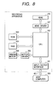
- Fig. 8 is a block diagram of the whole of an apparatus for operating an ink discharge recording apparatus to which the liquid discharge head of the present invention is applied.
- the recording apparatus receives printing information as a control signal 401 from a host computer 300.
- the printing information is temporarily preserved in an input/output interface 301 in the recording apparatus and at the same time, is converted into data which can be processed in the recording apparatus, and is inputted to a CPU 302 serving also as head driving signal supplying means.
- the CPU 302 processes the data inputted thereto by the use of a peripheral unit such as a RAM 304 on the basis of a control program preserved in a ROM 303, and converts the data into data to be printed (image data).
- the CPU 302 makes driving data for driving a driving motor 306 for moving the recording paper and the liquid discharge head 200 to record the image data at a suitable position on the recording paper.
- the image data is transmitted to the liquid discharge head 200 through a head driver 307 and also, the motor driving data is transmitted to the driving motor 306 through a motor driver 305.
- the liquid discharge head 200 and the driving motor 306 are driven at controlled timing, whereby an image is formed.
- Recording mediums which can be applied to the recording apparatus as described above and to which liquid such as ink is imparted include various kinds of paper, OHP sheets, plastic materials used for compact discs, decoration plates, etc., fabrics, metal plates of aluminum, copper, etc., leather materials such as oxide, pigskin and artificial leather, woods such as lumber and plywood, bamboo material, plastic materials such as tiles, and three-dimensional structures such as sponges.
- the above-described recording apparatus covers a printer apparatus for effecting recording on various kinds of paper and OHP sheets, a recording apparatus for plastics for effecting recording on plastic materials such as compact discs, a recording apparatus for metals for effecting recording on metal plates, a recording apparatus for leather for effecting recording on leather, a recording apparatus for woods for effecting recording on woods, a recording apparatus for ceramics for effecting recording on ceramic materials, a recording apparatus for effecting recording on three-dimensional net-like structures such as sponges, a textile printing apparatus for effecting recording on fabrics, etc.
- the concentration of stress to the corner portion is avoided.
- the shape of the fixed portion being made into a shape expediting the dispersion of stress, the concentration of stress to a particular movable member can be prevented.
Landscapes
- Particle Formation And Scattering Control In Inkjet Printers (AREA)
- Ink Jet (AREA)
Applications Claiming Priority (2)
| Application Number | Priority Date | Filing Date | Title |
|---|---|---|---|
| JP34472298 | 1998-12-03 | ||
| JP34472298A JP3907329B2 (ja) | 1998-12-03 | 1998-12-03 | 液体吐出ヘッドおよび液体吐出装置 |
Publications (3)
| Publication Number | Publication Date |
|---|---|
| EP1005993A2 true EP1005993A2 (de) | 2000-06-07 |
| EP1005993A3 EP1005993A3 (de) | 2000-11-22 |
| EP1005993B1 EP1005993B1 (de) | 2007-02-28 |
Family
ID=18371480
Family Applications (1)
| Application Number | Title | Priority Date | Filing Date |
|---|---|---|---|
| EP99309714A Expired - Lifetime EP1005993B1 (de) | 1998-12-03 | 1999-12-02 | Flüssigkeitsausstosskopf und Flüssigkeitsausstossgerät |
Country Status (5)
| Country | Link |
|---|---|
| US (1) | US6491381B2 (de) |
| EP (1) | EP1005993B1 (de) |
| JP (1) | JP3907329B2 (de) |
| AT (1) | ATE355175T1 (de) |
| DE (1) | DE69935299T2 (de) |
Cited By (2)
| Publication number | Priority date | Publication date | Assignee | Title |
|---|---|---|---|---|
| EP1221720A3 (de) * | 2000-12-28 | 2007-08-01 | Canon Kabushiki Kaisha | Halbleiteranordnung, Herstellungsverfahren dafür, und Tintenstrahl-Anordnung |
| EP1829690A3 (de) * | 2006-03-03 | 2008-12-10 | Canon Finetech Inc. | Flüssigkeitsausstoßkopf |
Families Citing this family (4)
| Publication number | Priority date | Publication date | Assignee | Title |
|---|---|---|---|---|
| JP3862625B2 (ja) * | 2002-07-10 | 2006-12-27 | キヤノン株式会社 | 液体吐出ヘッドの製造方法 |
| JP2007230194A (ja) * | 2006-03-03 | 2007-09-13 | Canon Finetech Inc | インクジェット記録ヘッドおよび製造方法 |
| JP7439482B2 (ja) * | 2019-12-03 | 2024-02-28 | セイコーエプソン株式会社 | 液体噴射ヘッドおよび液体噴射システム |
| JP7505179B2 (ja) * | 2019-12-03 | 2024-06-25 | セイコーエプソン株式会社 | 液体噴射ヘッドおよび液体噴射システム |
Citations (1)
| Publication number | Priority date | Publication date | Assignee | Title |
|---|---|---|---|---|
| US4723129A (en) | 1977-10-03 | 1988-02-02 | Canon Kabushiki Kaisha | Bubble jet recording method and apparatus in which a heating element generates bubbles in a liquid flow path to project droplets |
Family Cites Families (5)
| Publication number | Priority date | Publication date | Assignee | Title |
|---|---|---|---|---|
| US5278585A (en) | 1992-05-28 | 1994-01-11 | Xerox Corporation | Ink jet printhead with ink flow directing valves |
| US5821962A (en) | 1995-06-02 | 1998-10-13 | Canon Kabushiki Kaisha | Liquid ejection apparatus and method |
| JP3372765B2 (ja) | 1996-07-12 | 2003-02-04 | キヤノン株式会社 | 液体吐出ヘッド、ヘッドカートリッジ、液体吐出装置、記録システム、ヘッドキット、および液体吐出ヘッドの製造方法 |
| US6374482B1 (en) | 1997-08-05 | 2002-04-23 | Canon Kabushiki Kaisha | Method of manufacturing a liquid discharge head |
| US6409317B1 (en) | 1998-08-21 | 2002-06-25 | Canon Kabushiki Kaisha | Liquid discharge head, liquid discharge method and liquid discharge apparatus |
-
1998
- 1998-12-03 JP JP34472298A patent/JP3907329B2/ja not_active Expired - Fee Related
-
1999
- 1999-12-01 US US09/452,207 patent/US6491381B2/en not_active Expired - Fee Related
- 1999-12-02 AT AT99309714T patent/ATE355175T1/de not_active IP Right Cessation
- 1999-12-02 DE DE69935299T patent/DE69935299T2/de not_active Expired - Lifetime
- 1999-12-02 EP EP99309714A patent/EP1005993B1/de not_active Expired - Lifetime
Patent Citations (1)
| Publication number | Priority date | Publication date | Assignee | Title |
|---|---|---|---|---|
| US4723129A (en) | 1977-10-03 | 1988-02-02 | Canon Kabushiki Kaisha | Bubble jet recording method and apparatus in which a heating element generates bubbles in a liquid flow path to project droplets |
Cited By (2)
| Publication number | Priority date | Publication date | Assignee | Title |
|---|---|---|---|---|
| EP1221720A3 (de) * | 2000-12-28 | 2007-08-01 | Canon Kabushiki Kaisha | Halbleiteranordnung, Herstellungsverfahren dafür, und Tintenstrahl-Anordnung |
| EP1829690A3 (de) * | 2006-03-03 | 2008-12-10 | Canon Finetech Inc. | Flüssigkeitsausstoßkopf |
Also Published As
| Publication number | Publication date |
|---|---|
| EP1005993B1 (de) | 2007-02-28 |
| EP1005993A3 (de) | 2000-11-22 |
| US20020140773A1 (en) | 2002-10-03 |
| JP3907329B2 (ja) | 2007-04-18 |
| ATE355175T1 (de) | 2006-03-15 |
| DE69935299D1 (de) | 2007-04-12 |
| DE69935299T2 (de) | 2007-06-28 |
| US6491381B2 (en) | 2002-12-10 |
| JP2000168085A (ja) | 2000-06-20 |
Similar Documents
| Publication | Publication Date | Title |
|---|---|---|
| US7832843B2 (en) | Liquid jet head | |
| TW466182B (en) | Inkjet printhead with top plate bubble management | |
| US8496318B2 (en) | Liquid drop ejection using dual feed ejector | |
| US6464342B1 (en) | Liquid discharge head, head cartridge mounted on liquid discharge head and liquid discharge apparatus, and method for manufacturing liquid discharge head | |
| US6439700B1 (en) | Liquid discharge head, liquid discharge method, head cartridge and liquid discharge device | |
| JP3697089B2 (ja) | インクジェットヘッド用基体、インクジェットヘッド、インクジェットカートリッジおよびインクジェット記録装置 | |
| KR100909132B1 (ko) | 액체 토출 장치 및 액체 토출 방법 | |
| US6491381B2 (en) | Liquid discharge head and liquid discharge apparatus | |
| US6196667B1 (en) | Liquid discharging head, method of manufacturing the liquid discharging head, head cartridge carrying the liquid discharging head thereon and liquid discharging apparatus | |
| US6183066B1 (en) | Ink jet recording head having a common wiring structure and ink jet recording apparatus | |
| US20070165078A1 (en) | Liquid ejection head, liquid cartridge, liquid ejection apparatus, image forming apparatus and manufacturing method of liquid ejecting head | |
| EP1005992B1 (de) | Substrat für einen Flüssigkeitsausstosskopf, Flüssigkeitsausstosskopf und Flüssigkeitsausstossgerät | |
| JP3959837B2 (ja) | インクジェットヘッド | |
| EP0037624B1 (de) | Kopf für einen Tintenstrahldrucker | |
| JPH06126943A (ja) | インクジェット記録ヘッドおよびインクジェット記録装置 | |
| JP3867399B2 (ja) | インクジェット記録装置 | |
| US20080273056A1 (en) | Inkjet recording head and inkjet recording apparatus | |
| JP2001232822A (ja) | インクジェットヘッド | |
| EP1005989B1 (de) | Flüssigkeitsausstossverfahren, Flüssigkeitsausstosskopf, Verfahren zur Herstellung eines Flüssigkeitsausstosskopfes, Kopfkassette und Flüssigkeitsausstossgerät | |
| JP2001347675A (ja) | インクジェット記録装置 | |
| JPH0948123A (ja) | インクジェット記録ヘッドとその製造方法、インクジェット記録装置、および情報処理システム | |
| JP4854141B2 (ja) | 液体吐出記録ヘッド及び液体吐出記録装置 | |
| JP3548484B2 (ja) | 液体吐出ヘッド | |
| JP2000225705A (ja) | 液体吐出ヘッド用基板、液体吐出ヘッド、及び液体吐出装置 | |
| JPH064330B2 (ja) | インクジェットヘッド |
Legal Events
| Date | Code | Title | Description |
|---|---|---|---|
| PUAI | Public reference made under article 153(3) epc to a published international application that has entered the european phase |
Free format text: ORIGINAL CODE: 0009012 |
|
| AK | Designated contracting states |
Kind code of ref document: A2 Designated state(s): AT BE CH CY DE DK ES FI FR GB GR IE IT LI LU MC NL PT SE |
|
| AX | Request for extension of the european patent |
Free format text: AL;LT;LV;MK;RO;SI |
|
| PUAL | Search report despatched |
Free format text: ORIGINAL CODE: 0009013 |
|
| AK | Designated contracting states |
Kind code of ref document: A3 Designated state(s): AT BE CH CY DE DK ES FI FR GB GR IE IT LI LU MC NL PT SE |
|
| AX | Request for extension of the european patent |
Free format text: AL;LT;LV;MK;RO;SI |
|
| RIC1 | Information provided on ipc code assigned before grant |
Free format text: 7B 41J 2/14 A, 7B 41J 2/055 B |
|
| 17P | Request for examination filed |
Effective date: 20010409 |
|
| AKX | Designation fees paid |
Free format text: AT BE CH CY DE DK ES FI FR GB GR IE IT LI LU MC NL PT SE |
|
| 17Q | First examination report despatched |
Effective date: 20040505 |
|
| GRAP | Despatch of communication of intention to grant a patent |
Free format text: ORIGINAL CODE: EPIDOSNIGR1 |
|
| GRAS | Grant fee paid |
Free format text: ORIGINAL CODE: EPIDOSNIGR3 |
|
| GRAA | (expected) grant |
Free format text: ORIGINAL CODE: 0009210 |
|
| AK | Designated contracting states |
Kind code of ref document: B1 Designated state(s): AT BE CH CY DE DK ES FI FR GB GR IE IT LI LU MC NL PT SE |
|
| PG25 | Lapsed in a contracting state [announced via postgrant information from national office to epo] |
Ref country code: NL Free format text: LAPSE BECAUSE OF FAILURE TO SUBMIT A TRANSLATION OF THE DESCRIPTION OR TO PAY THE FEE WITHIN THE PRESCRIBED TIME-LIMIT Effective date: 20070228 Ref country code: LI Free format text: LAPSE BECAUSE OF FAILURE TO SUBMIT A TRANSLATION OF THE DESCRIPTION OR TO PAY THE FEE WITHIN THE PRESCRIBED TIME-LIMIT Effective date: 20070228 Ref country code: FI Free format text: LAPSE BECAUSE OF FAILURE TO SUBMIT A TRANSLATION OF THE DESCRIPTION OR TO PAY THE FEE WITHIN THE PRESCRIBED TIME-LIMIT Effective date: 20070228 Ref country code: DK Free format text: LAPSE BECAUSE OF FAILURE TO SUBMIT A TRANSLATION OF THE DESCRIPTION OR TO PAY THE FEE WITHIN THE PRESCRIBED TIME-LIMIT Effective date: 20070228 Ref country code: CH Free format text: LAPSE BECAUSE OF FAILURE TO SUBMIT A TRANSLATION OF THE DESCRIPTION OR TO PAY THE FEE WITHIN THE PRESCRIBED TIME-LIMIT Effective date: 20070228 Ref country code: BE Free format text: LAPSE BECAUSE OF FAILURE TO SUBMIT A TRANSLATION OF THE DESCRIPTION OR TO PAY THE FEE WITHIN THE PRESCRIBED TIME-LIMIT Effective date: 20070228 Ref country code: AT Free format text: LAPSE BECAUSE OF FAILURE TO SUBMIT A TRANSLATION OF THE DESCRIPTION OR TO PAY THE FEE WITHIN THE PRESCRIBED TIME-LIMIT Effective date: 20070228 |
|
| REG | Reference to a national code |
Ref country code: GB Ref legal event code: FG4D |
|
| REG | Reference to a national code |
Ref country code: CH Ref legal event code: EP |
|
| REF | Corresponds to: |
Ref document number: 69935299 Country of ref document: DE Date of ref document: 20070412 Kind code of ref document: P |
|
| REG | Reference to a national code |
Ref country code: IE Ref legal event code: FG4D |
|
| PG25 | Lapsed in a contracting state [announced via postgrant information from national office to epo] |
Ref country code: SE Free format text: LAPSE BECAUSE OF FAILURE TO SUBMIT A TRANSLATION OF THE DESCRIPTION OR TO PAY THE FEE WITHIN THE PRESCRIBED TIME-LIMIT Effective date: 20070531 |
|
| PG25 | Lapsed in a contracting state [announced via postgrant information from national office to epo] |
Ref country code: ES Free format text: LAPSE BECAUSE OF FAILURE TO SUBMIT A TRANSLATION OF THE DESCRIPTION OR TO PAY THE FEE WITHIN THE PRESCRIBED TIME-LIMIT Effective date: 20070608 |
|
| PG25 | Lapsed in a contracting state [announced via postgrant information from national office to epo] |
Ref country code: PT Free format text: LAPSE BECAUSE OF FAILURE TO SUBMIT A TRANSLATION OF THE DESCRIPTION OR TO PAY THE FEE WITHIN THE PRESCRIBED TIME-LIMIT Effective date: 20070730 |
|
| NLV1 | Nl: lapsed or annulled due to failure to fulfill the requirements of art. 29p and 29m of the patents act | ||
| REG | Reference to a national code |
Ref country code: CH Ref legal event code: PL |
|
| EN | Fr: translation not filed | ||
| PLBE | No opposition filed within time limit |
Free format text: ORIGINAL CODE: 0009261 |
|
| STAA | Information on the status of an ep patent application or granted ep patent |
Free format text: STATUS: NO OPPOSITION FILED WITHIN TIME LIMIT |
|
| 26N | No opposition filed |
Effective date: 20071129 |
|
| PG25 | Lapsed in a contracting state [announced via postgrant information from national office to epo] |
Ref country code: IT Free format text: LAPSE BECAUSE OF FAILURE TO SUBMIT A TRANSLATION OF THE DESCRIPTION OR TO PAY THE FEE WITHIN THE PRESCRIBED TIME-LIMIT Effective date: 20070228 Ref country code: GR Free format text: LAPSE BECAUSE OF FAILURE TO SUBMIT A TRANSLATION OF THE DESCRIPTION OR TO PAY THE FEE WITHIN THE PRESCRIBED TIME-LIMIT Effective date: 20070529 Ref country code: FR Free format text: LAPSE BECAUSE OF FAILURE TO SUBMIT A TRANSLATION OF THE DESCRIPTION OR TO PAY THE FEE WITHIN THE PRESCRIBED TIME-LIMIT Effective date: 20071019 |
|
| PG25 | Lapsed in a contracting state [announced via postgrant information from national office to epo] |
Ref country code: MC Free format text: LAPSE BECAUSE OF NON-PAYMENT OF DUE FEES Effective date: 20071231 |
|
| PG25 | Lapsed in a contracting state [announced via postgrant information from national office to epo] |
Ref country code: IE Free format text: LAPSE BECAUSE OF NON-PAYMENT OF DUE FEES Effective date: 20071203 |
|
| PG25 | Lapsed in a contracting state [announced via postgrant information from national office to epo] |
Ref country code: FR Free format text: LAPSE BECAUSE OF FAILURE TO SUBMIT A TRANSLATION OF THE DESCRIPTION OR TO PAY THE FEE WITHIN THE PRESCRIBED TIME-LIMIT Effective date: 20070228 |
|
| PG25 | Lapsed in a contracting state [announced via postgrant information from national office to epo] |
Ref country code: CY Free format text: LAPSE BECAUSE OF FAILURE TO SUBMIT A TRANSLATION OF THE DESCRIPTION OR TO PAY THE FEE WITHIN THE PRESCRIBED TIME-LIMIT Effective date: 20070228 |
|
| PG25 | Lapsed in a contracting state [announced via postgrant information from national office to epo] |
Ref country code: LU Free format text: LAPSE BECAUSE OF NON-PAYMENT OF DUE FEES Effective date: 20071202 |
|
| PGFP | Annual fee paid to national office [announced via postgrant information from national office to epo] |
Ref country code: DE Payment date: 20131231 Year of fee payment: 15 Ref country code: GB Payment date: 20131217 Year of fee payment: 15 |
|
| REG | Reference to a national code |
Ref country code: DE Ref legal event code: R119 Ref document number: 69935299 Country of ref document: DE |
|
| GBPC | Gb: european patent ceased through non-payment of renewal fee |
Effective date: 20141202 |
|
| PG25 | Lapsed in a contracting state [announced via postgrant information from national office to epo] |
Ref country code: GB Free format text: LAPSE BECAUSE OF NON-PAYMENT OF DUE FEES Effective date: 20141202 Ref country code: DE Free format text: LAPSE BECAUSE OF NON-PAYMENT OF DUE FEES Effective date: 20150701 |