EP1006016A2 - Verrouillage de traction et unité de déclenchement - Google Patents
Verrouillage de traction et unité de déclenchement Download PDFInfo
- Publication number
- EP1006016A2 EP1006016A2 EP99123714A EP99123714A EP1006016A2 EP 1006016 A2 EP1006016 A2 EP 1006016A2 EP 99123714 A EP99123714 A EP 99123714A EP 99123714 A EP99123714 A EP 99123714A EP 1006016 A2 EP1006016 A2 EP 1006016A2
- Authority
- EP
- European Patent Office
- Prior art keywords
- traction
- override
- response
- controller
- lockout
- Prior art date
- Legal status (The legal status is an assumption and is not a legal conclusion. Google has not performed a legal analysis and makes no representation as to the accuracy of the status listed.)
- Granted
Links
Images



Classifications
-
- B—PERFORMING OPERATIONS; TRANSPORTING
- B60—VEHICLES IN GENERAL
- B60K—ARRANGEMENT OR MOUNTING OF PROPULSION UNITS OR OF TRANSMISSIONS IN VEHICLES; ARRANGEMENT OR MOUNTING OF PLURAL DIVERSE PRIME-MOVERS IN VEHICLES; AUXILIARY DRIVES FOR VEHICLES; INSTRUMENTATION OR DASHBOARDS FOR VEHICLES; ARRANGEMENTS IN CONNECTION WITH COOLING, AIR INTAKE, GAS EXHAUST OR FUEL SUPPLY OF PROPULSION UNITS IN VEHICLES
- B60K28/00—Safety devices for propulsion-unit control, specially adapted for, or arranged in, vehicles, e.g. preventing fuel supply or ignition in the event of potentially dangerous conditions
- B60K28/02—Safety devices for propulsion-unit control, specially adapted for, or arranged in, vehicles, e.g. preventing fuel supply or ignition in the event of potentially dangerous conditions responsive to conditions relating to the driver
- B60K28/04—Safety devices for propulsion-unit control, specially adapted for, or arranged in, vehicles, e.g. preventing fuel supply or ignition in the event of potentially dangerous conditions responsive to conditions relating to the driver responsive to presence or absence of the driver, e.g. to weight or lack thereof
-
- B—PERFORMING OPERATIONS; TRANSPORTING
- B62—LAND VEHICLES FOR TRAVELLING OTHERWISE THAN ON RAILS
- B62D—MOTOR VEHICLES; TRAILERS
- B62D63/00—Motor vehicles or trailers not otherwise provided for
-
- E—FIXED CONSTRUCTIONS
- E02—HYDRAULIC ENGINEERING; FOUNDATIONS; SOIL SHIFTING
- E02F—DREDGING; SOIL-SHIFTING
- E02F9/00—Component parts of dredgers or soil-shifting machines, not restricted to one of the kinds covered by groups E02F3/00 - E02F7/00
- E02F9/20—Drives; Control devices
- E02F9/22—Hydraulic or pneumatic drives
- E02F9/226—Safety arrangements, e.g. hydraulic driven fans, preventing cavitation, leakage, overheating
-
- E—FIXED CONSTRUCTIONS
- E02—HYDRAULIC ENGINEERING; FOUNDATIONS; SOIL SHIFTING
- E02F—DREDGING; SOIL-SHIFTING
- E02F9/00—Component parts of dredgers or soil-shifting machines, not restricted to one of the kinds covered by groups E02F3/00 - E02F7/00
- E02F9/24—Safety devices, e.g. for preventing overload
-
- B—PERFORMING OPERATIONS; TRANSPORTING
- B60—VEHICLES IN GENERAL
- B60R—VEHICLES, VEHICLE FITTINGS, OR VEHICLE PARTS, NOT OTHERWISE PROVIDED FOR
- B60R21/00—Arrangements or fittings on vehicles for protecting or preventing injuries to occupants or pedestrians in case of accidents or other traffic risks
- B60R21/02—Occupant safety arrangements or fittings, e.g. crash pads
Definitions
- the present invention relates to power machinery. More particularly, the present invention relates to an apparatus for controlling operation of a lockout system for power machinery.
- Power machines such as skid steer loaders, typically have a frame which supports a cab and a movable lift arm which, in turn, supports a work tool such as a bucket.
- the movable lift arm is pivotally coupled to the frame of the skid steer loader by power actuators which are commonly hydraulic cylinders.
- the tool is coupled to the lift arm by another power actuator which is also commonly a hydraulic cylinder.
- An operator manipulating the skid steer loader raises and lowers the lift arm, and manipulates the tool, by actuating the hydraulic cylinders coupled to the lift arm, and the hydraulic cylinder coupled to the tool.
- the lift arm moves generally vertically upward.
- the lift arm moves generally vertically downward.
- the operator can manipulate the tool (e.g., tilt the bucket) by controlling the hydraulic cylinder coupled to the lift arm and the working tool to increase or decrease in length, as desired.
- Skid steer loaders also commonly have an engine which drives a hydraulic pump to, in turn, power hydraulic traction motors which power movement of the skid steer loader.
- the traction motors are commonly coupled to the wheels through a drive mechanism such as a chain drive.
- the lift arm, the tool, the traction mechanism, or all three be rendered inoperable.
- the hydraulic cylinders used to raise and lower the lift arm are locked out of operation.
- an operator presence switch is coupled to the hydraulic circuit controlling the hydraulic cylinders to render the hydraulic lift cylinders inoperable when the operator presence switch indicates that the operator is in an unconventional operating position.
- movable operator restraint bars are provided. When the operator restraint bars are moved to a retracted or inoperative position, mechanical brakes or wheel locks lock the wheels of the skid steer loader.
- mechanical brakes or wheel locks lock the wheels of the skid steer loader.
- the present invention is drawn to a control system on a power machine which includes a first sensor sensing a first operating condition and providing a first sensor signal.
- An operator actuable override mechanism provides an override signal in response to actuation thereof.
- a controller is coupled to the first sensor, a power circuit, a traction lockout mechanism, and the override mechanism.
- the controller is configured to instate a lockout condition in response to the first sensor signal.
- the controller selectively overrides the lockout condition based on the override signal, and the first sensor signal.
- FIG. 1 is a side elevational view of a skid steer loader 10 of the present invention.
- Skid steer loader 10 includes a frame 12 supported by wheels 14.
- Frame 12 also supports a cab 16 which defines an operator compartment and which substantially encloses a seat 19 on which an operator sits to control skid steer loader 10.
- a seat bar 21 is pivotally coupled to a portion of cab 16. When the operator occupies seat 19, the operator then pivots seat bar 21 from the raised position (shown in phantom in FIG. 1) to the lowered position shown in FIG. 1.
- a lift arm 17 is coupled to frame 12 at pivot points 20 (only one of which is shown in FIG. 1, the other being identically disposed on the opposite side of loader 10).
- a pair of hydraulic cylinders 22 (only one of which is shown in FIG. 1) are pivotally coupled to frame 12 at pivot points 24 and to lift arm 17 at pivot points 26.
- Lift arm 17 is also coupled to a working tool which, in this preferred embodiment, is a bucket 28.
- Lift arm 17 is pivotally coupled to bucket 28 at pivot points 30.
- another hydraulic cylinder 32 is pivotally coupled to lift arm 17 at pivot point 34 and to bucket 28 at pivot point 36. While only one cylinder 32 is shown, it is to be understood that any desired number of cylinders could be used to work bucket 28 or any other suitable tool.
- the operator residing in cab 16 can manipulate lift arm 17 and bucket 28 by selectively actuating hydraulic cylinders 22 and 32.
- hydraulic cylinders 22 and 32 By actuating hydraulic cylinders 22 and causing hydraulic cylinders 22 to increase in length, the operator moves lift arm 17, and consequently bucket 28, generally vertically upward in the direction indicated by arrow 38.
- the operator Conversely, when the operator actuates cylinder 22 causing it to decrease in length bucket 28 moves generally vertically downward to the position shown in FIG. 1.
- the operator can also manipulate bucket 28 by actuating cylinder 32.
- bucket 28 tilts forward about pivot points 30.
- bucket 28 tilts rearward about pivot points 30.
- the tilting is generally along an arcuate path indicated by arrow 40.
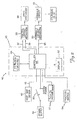
- FIG. 2 illustrates a control circuit 42 in accordance with one aspect of the present invention.
- Control circuit 42 includes controller 44 which receives inputs from seat bar sensor 48, ignition switch 50, push to operate (PTO) switch or button 52 and traction lock switch 54.
- Ignition switch 50 is coupled to a power supply 56. Upon closing of ignition switch 50, power is supplied from power supply 56 to the remainder of the system.
- controller 44 Based on the inputs received, controller 44 provides outputs to traction lock mechanism 58 and hydraulic lock mechanism 60. In one illustrative embodiment, controller 44 provides two outputs to traction lock mechanism 58, one output to hydraulic lock mechanism 60 and an output to display 62 which is integrated in controller 44 in the preferred embodiment. Controller 44 also provides an output to timer 64 which is also integrated in controller assembly 45 in the preferred embodiment.
- traction lock mechanism 58 and hydraulic lock mechanism 60 provide outputs to drive mechanism 66 and hydraulic circuit 68, respectively.
- Hydraulic circuit 68 provides an output to lift and tilt cylinders 22 and 32.
- Seat bar sensor 48 in the preferred embodiment, is a Hall effect position sensor more fully described in U.S. patent 5,542,493 issued August 6, 1996, and assigned to the same assignee as the present invention.
- Seat bar sensor 48 is activated when the operator pulls seat bar 21 into the lowered position shown in FIG. 1.
- seat bar sensor 48 provides a signal to controller 44 which is active when seat bar 21 is in the lowered position and inactive when seat bar 21 is in the raised position (or is moved out of the lowered position). While seat bar sensor 48 is preferably the Hall effect sensor described in the above-mentioned U.S. patent, any suitable position switch can be used as seat bar sensor 48.
- Ignition switch 50 is a typical key-type ignition switch or push button switch on a keypad used in supplying power from power supply 56 to the basic electrical system in skid steer loader 10. Upon the closure of ignition switch 50, power is also supplied to controller 44. Upon receiving power, controller 44 initializes itself and begins to run.
- Traction lock switch 54 can be embodied as an operator actuable input device, such as a push button, a switch on a control panel or steering lever hand grips in the operating compartment of the skid steer loader, or as an operator-controlled pedal actuated switch accessible from the operator compartment defined by cab 16.
- switch 54 is a pedal actuated switch
- the pedal is preferably configured as an over-center device.
- controller 44 removes power from traction lock mechanism 58, causing traction lock mechanism 58 to lock drive mechanism 66.
- PTO switch 52 is a manually operated switch which is also preferably located in the operator compartment defined by cab 16.
- Switch 52 can be of any suitable configuration, but is preferably a push button switch located on a dash panel in a forward region of the operator compartment. Switch 52 is described in greater detail below.
- traction lock mechanism 58 can take any number of suitable forms.
- traction lock mechanism 58 comprises the mechanism more fully described in U.S. Patent No. 5,551,523, issued on September 3, 1996, and assigned to the same assignee as the present application.
- traction lock mechanism 58 is configured as shown in FIG. 3 with a disc 59 having a number of lugs 61 mounted to a portion of the drive mechanism 66, such as one of the axles 63 or a drive train component used in driving wheels 14 on loader 10.
- a wedge 65 is manipulated by a solenoid slug or plunger 67 which is coupled to two coils 69 and 71.
- the coils are shown schematically and actually are coiled one inside the other around the slug 67.
- the wedge 65 is allowed to drop onto the disc 59 in the direction indicated by arrow 73, the wedge 65 is engaged by a lug 61 and locks up the axle 63 precluding rotation of axle 63 and therefore precluding movement of loader 10.
- the axle 63 is unlocked and the loader 10 is allowed to move.
- the two coils 69 and 71 operating the solenoid 67 include first coil 69 which is a relatively high current coil that is used to pull the wedge 65 up to clear lugs 61. Once the wedge 65 is pulled out of the path of lugs 61, the first coil 69 (the pull coil) is de-energized and second, hold coil 71, is energized.
- the hold coil 71 is a lower current coil which is used to hold the metal wedge 65 in place, out of engagement with the disc 59 mounted to the axle 63.
- controller 44 controls the coils to either allow the wedge 65 to drop into the path of lugs 61 on the drive mechanism 66 thereby locking the drive mechanism 66, or to pull and hold the wedge 65 out of engagement with the drive mechanism 66, thus allowing the loader 10 to move.
- Hydraulic lock mechanism 60 is more fully described in U.S. Patent No. 5,577,876 issued November 26, 1996 entitled HYDRAULIC INTERLOCK SYSTEM, and assigned to the same assignee as the present invention.
- hydraulic circuit 68 includes hydraulic valves which are actuated to provide fluid under pressure to cylinders 22 and 32 to achieve desired manipulation of cylinders 22 and 32.
- Hydraulic lock mechanism 60 in the preferred embodiment, includes any number of lock valves interposed between the valves in hydraulic circuit 68 and cylinders 22 and 32.
- the lock valves and hydraulic lock mechanism 60 Upon receiving appropriate control signals from controller 44, the lock valves and hydraulic lock mechanism 60 preclude hydraulic circuit 68 from providing fluid under pressure to cylinders 22 and 32, thereby locking operation of cylinders 22 and 32, or allowing only selected operations of cylinders 22.
- controller 44 Upon receiving such signal, controller 44 provides the appropriate signals to traction lock mechanism 58 to unlock drive mechanism 66 and allow movement of loader 10, and to hydraulic lock mechanism 60 to unlock hydraulic circuit 68 and allow manipulation of hydraulic cylinders 22 and 32. Also, controller 44 provides signals to display 62 which indicates that seat bar 21 is in the lowered position, hydraulic lock mechanism 60 has been sent a signal by controller 44 to unlock hydraulic circuit 68, traction lock mechanism 58 has been sent a signal by controller 44 to unlock drive mechanism 66 and controller 44 does not detect any system problems.
- controller 44 If controller 44 has not received a signal from seat bar sensor 48 indicating seat bar 21 is in the down position (as shown in FIG. 1) controller 44 provides appropriate signals to traction lock mechanism 58 and hydraulic lock mechanism 60, locking drive mechanism 66 and hydraulic circuit 68. This is described in greater detail below.
- seat bar sensor 48 provides controller 44 with a signal indicating that seat bar 21 has been raised or lowered. Controller 44 then provides output signals to traction lock mechanism 58 to lock out drive mechanism 66 and hydraulic lock mechanism 60 to lock out hydraulic circuit 68. This condition is also described in greater detail below.
- traction lock switch 54 which, in the preferred embodiment, is actuated by an over-center pedal device.
- controller 44 provides an output signal to traction lock mechanism 58 to lock drive mechanism 66.
- traction lock switch 54 By reverse actuation of traction lock switch 54, which will remove the signal to controller 44, the state of traction lock mechanism 58 and drive mechanism 66 will once again depend upon the signals received from seat bar sensor 48.
- FIG. 4 illustrates one embodiment of switch 52.
- Switch 52 is illustratively a push button actuable switch located on a front dash in cab 16 or on a front display panel, forwardly located in cab 16.
- switch 52 can be located at any suitable position on loader 10, and can be configured in any manner.
- controller 44 receives a signal indicative of that depression, and takes various actions, depending upon a current state of various operating and sensor parameters.
- FIG. 5 is a flow diagram illustrating the operation of circuit 42 in response to depression of switch 52 in accordance with one aspect of the present invention.
- controller 44 provides signals to traction lockout mechanism 58 and hydraulic lockout mechanism 60 to lock drive mechanism 66 and hydraulic circuit 68 such that the loader 10 cannot be driven, and such that the lift and tilt functions (or cylinders) are locked. This is indicated by block 84.
- Controller 44 in response to the signal received based on depression of button or switch 52, provides signals to traction lockout mechanism 58 and hydraulic lockout mechanism 60 to unlock the traction drive mechanism 66 and the lift and tilt cylinders in hydraulic circuit 68. This is indicated by block 88. Controller 44 also provides signals to display 62 to provide a display indicating the current state of circuit 42 (e.g., that the traction drive mechanism is enabled and the lift and tilt functions are also enabled). In one illustrative embodiment, display 62 is simply embodied as a green indicator light on a dash or display panel in cab 16. In that embodiment, controller 44 simply provides a signal to the indicator light causing the indicator light to remain lit.
- loaders such as loader 10
- loaders are often equipped with a backhoe attachment which includes its own seat mounted outside and to the front of cab 16.
- seat bar sensor 48 typically indicates that seat bar 21 is in the raised position.
- the seat provided on the backhoe attachment is commonly a swivel seat so that the operator can face in a direction to operate the backhoe attachment, and swivel around to face cab 16.
- PTO switch 52 is provided for overriding the traction lockout condition instated by controller 44 in response to signals from seat bar sensor 48 indicating that seat bar 21 is in the raised position.
- seat bar sensor 48 provides controller 44 with the signal indicative of that. This is true, regardless of whether loader 10 is started with seat bar 21 in the raised position, or whether loader 10 is started with seat bar 21 in the lowered position, and seat bar 21 is subsequently raised (such as when processing continues from block 94 in FIG. 5). In any case, when seat bar 21 is in the raised position, controller 44 controls traction lockout mechanism 58 and hydraulic lockout mechanism 60 to lock the traction, lift and tilt functions of loader 10. This is indicated by block 98 in FIG. 6.
- the traction lock state (in which the drive mechanism 66 is locked) can be overridden by the operator, by simply depressing button 52. Therefore, for instance, when the operator is operating a backhoe attachment, and the operator wishes to drive loader 10, the operator can simply swivel the backhoe seat, depress button 52, and move loader 10 into the desired position. This is indicated by blocks 100 and 102.
- Controller 44 can control circuit 42 in a number of different ways to override the traction lockout condition. For instance, controller 44 can place circuit 42 in the traction override condition (overriding the traction lockout condition) momentarily, in the instance in which switch 52 is implemented as a momentary switch. Similarly, controller 44 can place circuit 42 in the traction lock override condition for a predetermined time period, once switch 52 has been depressed and then automatically revert to the traction lockout condition after the predetermined time period. In the illustrative embodiment, however, depression of switch 52 simply toggles operation of controller 44. In other words, the first time push button 52 is depressed when seat bar 21 is in the raised position, controller 44 controls circuit 42 to enter the traction lock override condition in which the drive mechanism 66 is unlocked.
- Controller 44 retains circuit 42 in that condition until either seat bar 21 is lowered, or until button 52 is again depressed. If seat bar 21 is lowered, control reverts to block 84 in FIG. 5 in which lift, tilt and traction functions are all locked again. This is indicated by blocks 104 and 106 in FIG. 6. However, if button 52 is subsequently pressed, controller 44 simply toggles operation of circuit 42 such that circuit 42 is again placed in the traction lock state in which drive mechanism 66 is locked. Therefore, once the operator has moved loader 10 into the desired position (in the example in which the backhoe attachment is mounted on loader 10) the operator can then again simply depress button 52 to lock drive mechanism 66 and continue operation of the backhoe attachment. This is indicated by block 108 in FIG. 6.
- controller 44 can provide an appropriate display on display 62 indicating that either the traction lock, or the traction lock override conditions have been instated. For instance, where display 62 is simply a light on the dashboard, the light can be controlled to flash in one or more flash patterns, depending on the particular condition which is then instated.
- the present invention provides an efficient mechanism by which an operator can temporarily override lockout conditions previously instated by the control system.
- the operator can override the traction lock condition (or state) and can also be used to initially unlock various loader functions.
- the override states are also terminated in a convenient manner (such as by moving the seat bar or again depressing switch 52). Such a mechanism enhances the functionality of loader 10.
Landscapes
- Engineering & Computer Science (AREA)
- Mining & Mineral Resources (AREA)
- Civil Engineering (AREA)
- General Engineering & Computer Science (AREA)
- Structural Engineering (AREA)
- Chemical & Material Sciences (AREA)
- Combustion & Propulsion (AREA)
- Transportation (AREA)
- Mechanical Engineering (AREA)
- Operation Control Of Excavators (AREA)
- Component Parts Of Construction Machinery (AREA)
- Servomotors (AREA)
Applications Claiming Priority (2)
| Application Number | Priority Date | Filing Date | Title |
|---|---|---|---|
| US09/203,192 US6189646B1 (en) | 1998-11-30 | 1998-11-30 | Traction lock/momentary override |
| US203192 | 1998-11-30 |
Publications (3)
| Publication Number | Publication Date |
|---|---|
| EP1006016A2 true EP1006016A2 (fr) | 2000-06-07 |
| EP1006016A3 EP1006016A3 (fr) | 2000-12-27 |
| EP1006016B1 EP1006016B1 (fr) | 2008-08-06 |
Family
ID=22752899
Family Applications (1)
| Application Number | Title | Priority Date | Filing Date |
|---|---|---|---|
| EP99123714A Expired - Lifetime EP1006016B1 (fr) | 1998-11-30 | 1999-11-29 | Verrouillage de traction et unité de déclenchement |
Country Status (8)
| Country | Link |
|---|---|
| US (1) | US6189646B1 (fr) |
| EP (1) | EP1006016B1 (fr) |
| JP (1) | JP2000199242A (fr) |
| KR (1) | KR20000057020A (fr) |
| AU (1) | AU5824099A (fr) |
| CA (1) | CA2288409C (fr) |
| DE (1) | DE69939247D1 (fr) |
| ES (1) | ES2310027T3 (fr) |
Cited By (1)
| Publication number | Priority date | Publication date | Assignee | Title |
|---|---|---|---|---|
| WO2001057324A1 (fr) * | 2000-02-01 | 2001-08-09 | Clark Equipment Company | Dispositif de commande d'un outil de machine a moteur |
Families Citing this family (11)
| Publication number | Priority date | Publication date | Assignee | Title |
|---|---|---|---|---|
| US6519509B1 (en) * | 2000-06-22 | 2003-02-11 | Stonewater Software, Inc. | System and method for monitoring and controlling energy distribution |
| US6316891B1 (en) * | 2000-08-15 | 2001-11-13 | Deere & Company | Interlock circuit for a lawn and garden tractor |
| JP3953382B2 (ja) * | 2002-08-06 | 2007-08-08 | 株式会社クボタ | 作業機のエンジン自動停止解除構造 |
| US7128177B2 (en) * | 2003-04-10 | 2006-10-31 | Delta Systems, Inc. | Reverse operation safety circuit |
| ATE515630T1 (de) * | 2003-07-22 | 2011-07-15 | Kobelco Constr Machinery Ltd | Baumaschine |
| US7192100B2 (en) * | 2004-09-27 | 2007-03-20 | Clark Equipment Company | Power machine having traction lock with speed-range selector |
| DE102009046274A1 (de) * | 2009-11-02 | 2011-05-12 | Robert Bosch Gmbh | Sicherheitsvorrichtung für einen Kraftfahrzeug-Service-Arbeitsplatz |
| US8950525B2 (en) | 2012-09-04 | 2015-02-10 | Clark Equipment Company | Front power takeoff for utility vehicle |
| US10336292B2 (en) | 2016-08-30 | 2019-07-02 | Clark Equipment Company | Seat belt |
| JP6844922B2 (ja) * | 2017-01-30 | 2021-03-17 | 三菱ロジスネクスト株式会社 | 荷役車両のインターロック装置 |
| KR20230152183A (ko) | 2017-04-19 | 2023-11-02 | 클라크 이큅먼트 컴파니 | 로더 프레임 |
Citations (5)
| Publication number | Priority date | Publication date | Assignee | Title |
|---|---|---|---|---|
| US4389154A (en) | 1981-05-13 | 1983-06-21 | Sperry Corporation | Time delay for a seat switch activated loader boom lock |
| US4955452A (en) | 1989-04-20 | 1990-09-11 | Trak International, Inc. | Locking apparatus for skid steer loader |
| US5542493A (en) | 1994-02-22 | 1996-08-06 | Clark Equipment Company | Hall effect sensor assembly |
| US5551523A (en) | 1994-02-18 | 1996-09-03 | Clark Equipment Company | Traction lock |
| US5577876A (en) | 1994-02-22 | 1996-11-26 | Clark Equipment Company | Hydraulic interblock system |
Family Cites Families (72)
| Publication number | Priority date | Publication date | Assignee | Title |
|---|---|---|---|---|
| US2606626A (en) | 1952-08-12 | Automatic control device for the | ||
| US3215221A (en) | 1964-03-06 | 1965-11-02 | M Blatt Co | Automobile seat belt assembly |
| US3340523A (en) | 1964-10-14 | 1967-09-05 | Robert L Whitman | Seat-belt safety systems |
| US3449714A (en) | 1965-05-06 | 1969-06-10 | Elizabeth L Farley | Vehicle seatbelt safety system |
| US3455410A (en) | 1967-04-27 | 1969-07-15 | James W Wilson | Passenger safety system for automobiles |
| US3507350A (en) | 1967-11-24 | 1970-04-21 | Allis Chalmers Mfg Co | Vehicle directional switch and seat switch interlock |
| US3500946A (en) | 1968-01-02 | 1970-03-17 | Allis Chalmers Mfg Co | Seat operated power cutoff time delay |
| US3487451A (en) | 1968-03-06 | 1969-12-30 | John G Fontaine | Brake control means for vehicles |
| GB1378745A (en) | 1970-12-18 | 1974-12-27 | Nacdonald K D | Apparatus for ensuring or encouraging the wearing of safety belts in vehilces |
| US3740711A (en) | 1971-12-09 | 1973-06-19 | Gen Motors Corp | System for encouraging use of seat belts in a motor vehicle |
| US3749866A (en) | 1972-05-01 | 1973-07-31 | Amp Inc | Foam seat sensor |
| US4096468A (en) | 1972-07-31 | 1978-06-20 | Chrysler Corporation | Solid state sequence logic circuit |
| US3788431A (en) | 1972-08-10 | 1974-01-29 | Clark Equipment Co | Seat safety brake control system |
| US3790223A (en) | 1972-09-26 | 1974-02-05 | J Fontaine | Control system for brakes |
| US3838748A (en) | 1973-01-30 | 1974-10-01 | Ridersafe Syst Inc | Safety system for vehicles |
| US3864668A (en) | 1973-01-31 | 1975-02-04 | Amp Inc | Seat belt warning and ignition interlock system |
| JPS542447B2 (fr) | 1973-07-28 | 1979-02-07 | ||
| JPS5094632A (fr) | 1973-12-24 | 1975-07-28 | ||
| US3892294A (en) | 1974-02-28 | 1975-07-01 | Eaton Corp | Dead-man parking brake |
| US3927776A (en) | 1974-03-04 | 1975-12-23 | Douglas W Steiger | Safety lock device for the control levers of a front end loader |
| US3912939A (en) | 1974-04-01 | 1975-10-14 | Lectron Products | Method and apparatus for detecting the occupancy of a vehicle seat |
| JPS5127242A (en) | 1974-08-30 | 1976-03-06 | Komatsu Mfg Co Ltd | Kensetsusharyo no jidoanzenkeihosochi |
| US4103842A (en) | 1975-07-07 | 1978-08-01 | Repa Feinstanzwerk Gmbh | Locking sensor for belt retractor |
| JPS5248201A (en) | 1975-10-15 | 1977-04-16 | Hokushin Electric Works | Device for operating power shovel |
| US4019602A (en) | 1976-06-07 | 1977-04-26 | Caterpillar Tractor Co. | Seat actuated fluid drive neutralizing arrangement |
| US4053868A (en) | 1976-12-27 | 1977-10-11 | Caterpillar Tractor Co. | Vehicle system monitor |
| US4091889A (en) | 1977-01-17 | 1978-05-30 | Towmotor Corporation | Creeper - deadman |
| US4116296A (en) | 1977-03-09 | 1978-09-26 | Eaton Corporation | Automatic seat brake |
| FR2414423A1 (fr) | 1978-01-17 | 1979-08-10 | Neiman Sa | Dispositif d'asservissement d'un antivol de vehicule automobile a la fermeture d'une ceinture de securite |
| US4172980A (en) | 1978-06-30 | 1979-10-30 | Towmotor Corporation | Device for disabling power under certain safety conditions |
| JPS5819494B2 (ja) | 1978-11-06 | 1983-04-18 | トヨタ自動車株式会社 | パツシブシ−トベルト装置 |
| US4267544A (en) | 1979-11-08 | 1981-05-12 | Towmotor Corporation | Magnetic control apparatus |
| US4285418A (en) | 1980-01-07 | 1981-08-25 | Towmotor Corporation | Friction coupling control system |
| JPS56112011A (en) | 1980-02-12 | 1981-09-04 | Japan Atomic Energy Res Inst | Composite superconductor |
| US4317500A (en) | 1980-02-22 | 1982-03-02 | Deere & Company | Safety start and shutdown system for vehicles having electrically activated power take-off |
| US4296410A (en) | 1980-02-25 | 1981-10-20 | Sprague Electric Company | Two-state Hall element proximity sensor device with lamp indicator |
| US4320819A (en) | 1980-03-06 | 1982-03-23 | Towmotor Corporation | Seat-operated brake assembly with brake protection means |
| US4355698A (en) | 1980-07-21 | 1982-10-26 | Clark Equipment Company | Brake and transmission control |
| US4361741A (en) | 1980-12-19 | 1982-11-30 | Towmotor Corporation | Switch actuator apparatus |
| US4397371A (en) | 1981-01-26 | 1983-08-09 | Clark Equipment Company | Loader operator restraint system |
| US4388980A (en) | 1981-01-26 | 1983-06-21 | Clark Equipment Company | Operator restraint for a loader |
| US4391344A (en) | 1981-01-26 | 1983-07-05 | Clark Equipment Company | Loader operator restraint |
| US4398618A (en) | 1981-02-27 | 1983-08-16 | Clark Equipment Company | Controller for electric traction motor |
| US4392544A (en) | 1981-03-02 | 1983-07-12 | Clark Equipment Company | Controller for electric traction motor |
| US4385863A (en) | 1981-05-13 | 1983-05-31 | Sperry Corporation | Seat interlock for skid-steer loader |
| US4480713A (en) | 1982-11-16 | 1984-11-06 | Owatonna Manufacturing Company, Inc. | Operator restraint/control lockout system |
| US4466504A (en) | 1983-02-03 | 1984-08-21 | Textron Inc. | Tractor seat-operated hydraulic valve control |
| US4546266A (en) | 1983-07-28 | 1985-10-08 | Zenick Walter N | Magnetically actuated interlock |
| US4550597A (en) | 1984-04-04 | 1985-11-05 | Trw Inc. | Method and apparatus for sensing relative movement between members |
| CA1209883A (fr) | 1984-05-15 | 1986-08-19 | Raymond W. Burke | Frein de surete |
| US4579191A (en) | 1984-11-05 | 1986-04-01 | J. I. Case Company | Operator restraint system |
| US4655313A (en) | 1985-08-26 | 1987-04-07 | Outboard Marine Corporation | Vehicle seat switch |
| US4796013A (en) | 1985-10-18 | 1989-01-03 | Aisin Seiki Kabushiki Kaisha | Capacitive occupancy detector apparatus |
| US4706194A (en) | 1985-12-13 | 1987-11-10 | United Technologies Automotive, Inc. | Multiplex control system for memory seat or the like load |
| JPS6368440A (ja) | 1986-09-11 | 1988-03-28 | N S K Warner Kk | パツシブシ−トベルトシステム |
| US4727353A (en) | 1987-01-21 | 1988-02-23 | Deere & Company | Monitor display system |
| US4955455A (en) * | 1987-08-21 | 1990-09-11 | Clark Equipment Company | Method for assembling a skid steer loader |
| US4759185A (en) | 1987-09-18 | 1988-07-26 | Deere & Company | Operator presence switch with service by-pass |
| US4856612A (en) | 1988-02-10 | 1989-08-15 | Ford New Holland, Inc. | Method of controlling the operation of a loader |
| US4871044A (en) | 1988-02-10 | 1989-10-03 | Ford New Holland, Inc. | Service override for loader interlock |
| US4844196A (en) | 1988-02-10 | 1989-07-04 | Ford New Holland, Inc. | Seat belt interlock for loaders |
| JPH0251934U (fr) | 1988-10-07 | 1990-04-13 | ||
| US4909560A (en) | 1989-02-27 | 1990-03-20 | Hoover Universal, Inc. | Digital linear position sensor |
| US5050700A (en) | 1989-06-05 | 1991-09-24 | Daewoo Heavy Industries Ltd. | Safety apparatus for a skid-steer loader |
| US4951963A (en) | 1989-10-02 | 1990-08-28 | Automotive Systems Laboratory, Inc. | Self-adjusting knee bolster |
| US5129478A (en) | 1990-07-31 | 1992-07-14 | Toyo Umpanki Co., Ltd. | Seat occupant restraining device |
| US5203440A (en) | 1992-06-24 | 1993-04-20 | Deere & Company | Interlock circuit for a vehicle with an optical second drive |
| US5425431A (en) | 1994-02-18 | 1995-06-20 | Clark Equipment Company | Interlock control system for power machine |
| DE69506594T2 (de) * | 1994-02-18 | 1999-04-29 | Clark Equipment Co., Woodcliff Lake, N.J. | Hall-Sensoranordnung |
| JP2682817B2 (ja) * | 1995-07-12 | 1997-11-26 | 新キャタピラー三菱株式会社 | 建設機械の操作遮断装置 |
| US5711391A (en) * | 1996-06-17 | 1998-01-27 | Clark Equipment Company | Auxiliary interlock control system for power machine |
| US5931254A (en) * | 1997-04-30 | 1999-08-03 | Clark Equipment Company | Non-contact operator presence sensor |
-
1998
- 1998-11-30 US US09/203,192 patent/US6189646B1/en not_active Expired - Lifetime
-
1999
- 1999-11-03 AU AU58240/99A patent/AU5824099A/en not_active Abandoned
- 1999-11-03 CA CA002288409A patent/CA2288409C/fr not_active Expired - Fee Related
- 1999-11-25 KR KR1019990052649A patent/KR20000057020A/ko not_active Withdrawn
- 1999-11-26 JP JP11336405A patent/JP2000199242A/ja active Pending
- 1999-11-29 EP EP99123714A patent/EP1006016B1/fr not_active Expired - Lifetime
- 1999-11-29 DE DE69939247T patent/DE69939247D1/de not_active Expired - Lifetime
- 1999-11-29 ES ES99123714T patent/ES2310027T3/es not_active Expired - Lifetime
Patent Citations (5)
| Publication number | Priority date | Publication date | Assignee | Title |
|---|---|---|---|---|
| US4389154A (en) | 1981-05-13 | 1983-06-21 | Sperry Corporation | Time delay for a seat switch activated loader boom lock |
| US4955452A (en) | 1989-04-20 | 1990-09-11 | Trak International, Inc. | Locking apparatus for skid steer loader |
| US5551523A (en) | 1994-02-18 | 1996-09-03 | Clark Equipment Company | Traction lock |
| US5542493A (en) | 1994-02-22 | 1996-08-06 | Clark Equipment Company | Hall effect sensor assembly |
| US5577876A (en) | 1994-02-22 | 1996-11-26 | Clark Equipment Company | Hydraulic interblock system |
Cited By (2)
| Publication number | Priority date | Publication date | Assignee | Title |
|---|---|---|---|---|
| WO2001057324A1 (fr) * | 2000-02-01 | 2001-08-09 | Clark Equipment Company | Dispositif de commande d'un outil de machine a moteur |
| US6923285B1 (en) | 2000-02-01 | 2005-08-02 | Clark Equipment Company | Attachment control device |
Also Published As
| Publication number | Publication date |
|---|---|
| AU5824099A (en) | 2000-06-01 |
| ES2310027T3 (es) | 2008-12-16 |
| US6189646B1 (en) | 2001-02-20 |
| EP1006016A3 (fr) | 2000-12-27 |
| JP2000199242A (ja) | 2000-07-18 |
| CA2288409C (fr) | 2007-03-06 |
| EP1006016B1 (fr) | 2008-08-06 |
| KR20000057020A (ko) | 2000-09-15 |
| CA2288409A1 (fr) | 2000-05-30 |
| DE69939247D1 (de) | 2008-09-18 |
Similar Documents
| Publication | Publication Date | Title |
|---|---|---|
| US5425431A (en) | Interlock control system for power machine | |
| US7142967B2 (en) | Features of main control computer for a power machine | |
| EP0978406B1 (fr) | Télécommande pour un outil de travail d'un véhicule utilitaire | |
| EP0814207B1 (fr) | Système de commande de verrouillage auxiliaire pour machine motrice | |
| CA2288409C (fr) | Blocage de traction a priorite momentanee | |
| WO2000064231A9 (fr) | Caracteristiques d'un ordinateur central de commande pour une machine motrice | |
| JPH0685449U (ja) | 排土板制御装置 | |
| US7192100B2 (en) | Power machine having traction lock with speed-range selector | |
| CN118202121A (zh) | 工程机械 | |
| JP3357232B2 (ja) | 作業機械の安全装置 | |
| EP0668181B1 (fr) | Système de commande de verrouillage pour machine motrice | |
| AU700677B2 (en) | Interlock control system for power machine | |
| KR20220014632A (ko) | 건설 기계의 구동 방법 | |
| JPH07247572A (ja) | 建設機械のブレード制御装置 |
Legal Events
| Date | Code | Title | Description |
|---|---|---|---|
| PUAI | Public reference made under article 153(3) epc to a published international application that has entered the european phase |
Free format text: ORIGINAL CODE: 0009012 |
|
| 17P | Request for examination filed |
Effective date: 19991228 |
|
| AK | Designated contracting states |
Kind code of ref document: A2 Designated state(s): BE DE ES FR GB IT |
|
| AX | Request for extension of the european patent |
Free format text: AL;LT;LV;MK;RO;SI |
|
| PUAL | Search report despatched |
Free format text: ORIGINAL CODE: 0009013 |
|
| AK | Designated contracting states |
Kind code of ref document: A3 Designated state(s): AT BE CH CY DE DK ES FI FR GB GR IE IT LI LU MC NL PT SE |
|
| AX | Request for extension of the european patent |
Free format text: AL;LT;LV;MK;RO;SI |
|
| AKX | Designation fees paid |
Free format text: BE DE ES FR GB IT |
|
| GRAP | Despatch of communication of intention to grant a patent |
Free format text: ORIGINAL CODE: EPIDOSNIGR1 |
|
| GRAC | Information related to communication of intention to grant a patent modified |
Free format text: ORIGINAL CODE: EPIDOSCIGR1 |
|
| GRAS | Grant fee paid |
Free format text: ORIGINAL CODE: EPIDOSNIGR3 |
|
| GRAA | (expected) grant |
Free format text: ORIGINAL CODE: 0009210 |
|
| AK | Designated contracting states |
Kind code of ref document: B1 Designated state(s): BE DE ES FR GB IT |
|
| REG | Reference to a national code |
Ref country code: GB Ref legal event code: FG4D |
|
| REF | Corresponds to: |
Ref document number: 69939247 Country of ref document: DE Date of ref document: 20080918 Kind code of ref document: P |
|
| REG | Reference to a national code |
Ref country code: ES Ref legal event code: FG2A Ref document number: 2310027 Country of ref document: ES Kind code of ref document: T3 |
|
| PLBE | No opposition filed within time limit |
Free format text: ORIGINAL CODE: 0009261 |
|
| STAA | Information on the status of an ep patent application or granted ep patent |
Free format text: STATUS: NO OPPOSITION FILED WITHIN TIME LIMIT |
|
| 26N | No opposition filed |
Effective date: 20090507 |
|
| PGFP | Annual fee paid to national office [announced via postgrant information from national office to epo] |
Ref country code: BE Payment date: 20090219 Year of fee payment: 10 |
|
| BERE | Be: lapsed |
Owner name: CLARK EQUIPMENT CY Effective date: 20091130 |
|
| PG25 | Lapsed in a contracting state [announced via postgrant information from national office to epo] |
Ref country code: BE Free format text: LAPSE BECAUSE OF NON-PAYMENT OF DUE FEES Effective date: 20091130 |
|
| PGFP | Annual fee paid to national office [announced via postgrant information from national office to epo] |
Ref country code: FR Payment date: 20101202 Year of fee payment: 12 |
|
| PGFP | Annual fee paid to national office [announced via postgrant information from national office to epo] |
Ref country code: ES Payment date: 20101125 Year of fee payment: 12 |
|
| REG | Reference to a national code |
Ref country code: FR Ref legal event code: ST Effective date: 20120731 |
|
| PG25 | Lapsed in a contracting state [announced via postgrant information from national office to epo] |
Ref country code: FR Free format text: LAPSE BECAUSE OF NON-PAYMENT OF DUE FEES Effective date: 20111130 |
|
| REG | Reference to a national code |
Ref country code: ES Ref legal event code: FD2A Effective date: 20130605 |
|
| PG25 | Lapsed in a contracting state [announced via postgrant information from national office to epo] |
Ref country code: ES Free format text: LAPSE BECAUSE OF NON-PAYMENT OF DUE FEES Effective date: 20111130 |
|
| PGFP | Annual fee paid to national office [announced via postgrant information from national office to epo] |
Ref country code: DE Payment date: 20181128 Year of fee payment: 20 |
|
| PGFP | Annual fee paid to national office [announced via postgrant information from national office to epo] |
Ref country code: IT Payment date: 20181123 Year of fee payment: 20 Ref country code: GB Payment date: 20181127 Year of fee payment: 20 |
|
| REG | Reference to a national code |
Ref country code: DE Ref legal event code: R071 Ref document number: 69939247 Country of ref document: DE |
|
| REG | Reference to a national code |
Ref country code: GB Ref legal event code: PE20 Expiry date: 20191128 |
|
| PG25 | Lapsed in a contracting state [announced via postgrant information from national office to epo] |
Ref country code: GB Free format text: LAPSE BECAUSE OF EXPIRATION OF PROTECTION Effective date: 20191128 |