EP1006040B1 - Direction assistée électrique - Google Patents
Direction assistée électrique Download PDFInfo
- Publication number
- EP1006040B1 EP1006040B1 EP99123937A EP99123937A EP1006040B1 EP 1006040 B1 EP1006040 B1 EP 1006040B1 EP 99123937 A EP99123937 A EP 99123937A EP 99123937 A EP99123937 A EP 99123937A EP 1006040 B1 EP1006040 B1 EP 1006040B1
- Authority
- EP
- European Patent Office
- Prior art keywords
- electric motor
- gear
- steering apparatus
- axis
- eccentric
- Prior art date
- Legal status (The legal status is an assumption and is not a legal conclusion. Google has not performed a legal analysis and makes no representation as to the accuracy of the status listed.)
- Expired - Lifetime
Links
- 230000000694 effects Effects 0.000 claims description 5
- 238000004519 manufacturing process Methods 0.000 description 1
Images


Classifications
-
- B—PERFORMING OPERATIONS; TRANSPORTING
- B62—LAND VEHICLES FOR TRAVELLING OTHERWISE THAN ON RAILS
- B62D—MOTOR VEHICLES; TRAILERS
- B62D5/00—Power-assisted or power-driven steering
- B62D5/04—Power-assisted or power-driven steering electrical, e.g. using an electric servo-motor connected to, or forming part of, the steering gear
- B62D5/0409—Electric motor acting on the steering column
-
- B—PERFORMING OPERATIONS; TRANSPORTING
- B62—LAND VEHICLES FOR TRAVELLING OTHERWISE THAN ON RAILS
- B62D—MOTOR VEHICLES; TRAILERS
- B62D5/00—Power-assisted or power-driven steering
- B62D5/04—Power-assisted or power-driven steering electrical, e.g. using an electric servo-motor connected to, or forming part of, the steering gear
- B62D5/0403—Power-assisted or power-driven steering electrical, e.g. using an electric servo-motor connected to, or forming part of, the steering gear characterised by constructional features, e.g. common housing for motor and gear box
-
- F—MECHANICAL ENGINEERING; LIGHTING; HEATING; WEAPONS; BLASTING
- F16—ENGINEERING ELEMENTS AND UNITS; GENERAL MEASURES FOR PRODUCING AND MAINTAINING EFFECTIVE FUNCTIONING OF MACHINES OR INSTALLATIONS; THERMAL INSULATION IN GENERAL
- F16H—GEARING
- F16H57/00—General details of gearing
- F16H57/02—Gearboxes; Mounting gearing therein
- F16H57/021—Shaft support structures, e.g. partition walls, bearing eyes, casing walls or covers with bearings
- F16H57/022—Adjustment of gear shafts or bearings
- F16H2057/0222—Lateral adjustment
- F16H2057/0224—Lateral adjustment using eccentric bushes
-
- Y—GENERAL TAGGING OF NEW TECHNOLOGICAL DEVELOPMENTS; GENERAL TAGGING OF CROSS-SECTIONAL TECHNOLOGIES SPANNING OVER SEVERAL SECTIONS OF THE IPC; TECHNICAL SUBJECTS COVERED BY FORMER USPC CROSS-REFERENCE ART COLLECTIONS [XRACs] AND DIGESTS
- Y10—TECHNICAL SUBJECTS COVERED BY FORMER USPC
- Y10T—TECHNICAL SUBJECTS COVERED BY FORMER US CLASSIFICATION
- Y10T74/00—Machine element or mechanism
- Y10T74/18—Mechanical movements
- Y10T74/18568—Reciprocating or oscillating to or from alternating rotary
- Y10T74/18784—Reciprocating or oscillating to or from alternating rotary including bevel gears
-
- Y—GENERAL TAGGING OF NEW TECHNOLOGICAL DEVELOPMENTS; GENERAL TAGGING OF CROSS-SECTIONAL TECHNOLOGIES SPANNING OVER SEVERAL SECTIONS OF THE IPC; TECHNICAL SUBJECTS COVERED BY FORMER USPC CROSS-REFERENCE ART COLLECTIONS [XRACs] AND DIGESTS
- Y10—TECHNICAL SUBJECTS COVERED BY FORMER USPC
- Y10T—TECHNICAL SUBJECTS COVERED BY FORMER US CLASSIFICATION
- Y10T74/00—Machine element or mechanism
- Y10T74/19—Gearing
- Y10T74/1956—Adjustable
- Y10T74/19565—Relative movable axes
-
- Y—GENERAL TAGGING OF NEW TECHNOLOGICAL DEVELOPMENTS; GENERAL TAGGING OF CROSS-SECTIONAL TECHNOLOGIES SPANNING OVER SEVERAL SECTIONS OF THE IPC; TECHNICAL SUBJECTS COVERED BY FORMER USPC CROSS-REFERENCE ART COLLECTIONS [XRACs] AND DIGESTS
- Y10—TECHNICAL SUBJECTS COVERED BY FORMER USPC
- Y10T—TECHNICAL SUBJECTS COVERED BY FORMER US CLASSIFICATION
- Y10T74/00—Machine element or mechanism
- Y10T74/19—Gearing
- Y10T74/19623—Backlash take-up
-
- Y—GENERAL TAGGING OF NEW TECHNOLOGICAL DEVELOPMENTS; GENERAL TAGGING OF CROSS-SECTIONAL TECHNOLOGIES SPANNING OVER SEVERAL SECTIONS OF THE IPC; TECHNICAL SUBJECTS COVERED BY FORMER USPC CROSS-REFERENCE ART COLLECTIONS [XRACs] AND DIGESTS
- Y10—TECHNICAL SUBJECTS COVERED BY FORMER USPC
- Y10T—TECHNICAL SUBJECTS COVERED BY FORMER US CLASSIFICATION
- Y10T74/00—Machine element or mechanism
- Y10T74/19—Gearing
- Y10T74/19642—Directly cooperating gears
- Y10T74/19698—Spiral
- Y10T74/19702—Screw and nut
- Y10T74/19721—Thread geometry
Definitions
- the present invention relates to a vehicle steering apparatus, and particularly relates to an electric power steering apparatus for turning steerable wheels of a vehicle.
- a known electric power steering apparatus for turning steerable wheels of a vehicle includes an input member to which steering torque is applied, a steering torque sensor operatively coupled with the input member, an electronic control unit, and an electric motor.
- the electronic control unit receives signals from the torque sensor, and possibly other sensors, and controls the electric motor.
- the electric motor has a motor shaft which rotates about a motor axis.
- the motor shaft is connected with a gearbox which provides a gear reduction between the motor shaft of the electric motor and an output pinion meshed with a linearly movable rack. Rotation of the output pinion causes the rack to move linearly to turn the steerable wheels.
- the gearbox typically includes a pair of meshed gears, such as a worm gear set. Some amount of backlash may be present between the pair of gears, whatever the configuration of the gears, in the gearbox.
- the backlash or amount by which the width of a tooth space exceeds the thickness of an engaging tooth measured on the pitch circle, results primarily from manufacturing tolerances. Excessive backlash can generate undesirable noise and cause the gears to wear. It is desirable for an electric power steering apparatus to include a means for adjusting backlash of the gears in the gearbox between the electric motor and the output pinion.
- JP 7 237 551 discloses a vehicle steering apparatus for turning steerable wheels of a vehicle, said apparatus comprising:
- JP 8 028 669 discloses a vehicle steering apparatus for turning steerable wheels of a vehicle, said apparatus comprising:
- the present invention is a vehicle steering apparatus for turning steerable wheels of a vehicle according to claim 1.
- the apparatus comprises a manually rotatable input member to which steering torque is applied, an output member rotatable to effect turning of the steerable wheels of the vehicle, and an electric motor for providing a drive force to rotate the output member as a function of the steering torque applied to the input member.
- the electric motor includes a motor shaft having an axis of rotation.
- First and second meshing gears transmit the drive force of the electric motor to the output member.
- the first gear is rotatable with the output member and the second gear is rotatable with the motor shaft about the axis of rotation.
- Adjusting means is provided for adjusting backlash between the first and second gears.
- the adjusting means includes mounting means for adjustably mounting the electric motor and the second gear relative to the first gear.
- the mounting means includes eccentric surface means for shifting the axis of rotation of the motor shaft and the second gear relative to the first gear.
- the mounting means includes an annular projection extending axially from a first end.of the electric motor.
- the annular projection has a cylindrical outer surface comprising a first eccentric surface.
- the first eccentric surface is centered on an eccentric axis which extends parallel to but radially offset from the axis rotation of the motor shaft.
- the vehicle steering apparatus further comprises a gearbox housing containing the first and second gears.
- the electric motor is adjustably mounted to the gearbox housing.
- the gearbox housing includes a second eccentric surface defining an opening for receiving the annular projection. The backlash between the first and second gears is adjusted by manually rotating the electric motor relative to the gearbox housing about the eccentric axis.
- the first and second gears are a spiroid gear set.
- the present invention relates to a vehicle steering apparatus, and particularly relates to an electric power steering apparatus for turning steerable wheels of a vehicle.
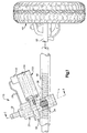
- Fig. 1 illustrates a power steering apparatus 10 for a vehicle, such as an automobile.
- the steering system 10 includes a vehicle steering wheel (not shown) and a rotatable input shaft 12 which is operatively coupled, in a manner not shown, for rotation with the vehicle steering wheel about an axis 14.
- a torque sensor 20 encircles the input shaft 12.
- the torque sensor 20 includes a sensor housing 22 (Fig. 2) and a pair of relatively movable members 24 and 26, respectively.
- the movable members 24, 26 of the torque sensor 20 have coils (not shown) which respond to relative rotation of the movable members and output an electrical signal over electrical lines 28 (Fig. 1) indicative of the direction and magnitude of the applied steering torque.
- a torsion bar 30 (Fig. 2) connects the input shaft 12 to an output shaft 32.
- the torsion bar 30 twists in response to steering torque applied to the steering wheel.
- the torsion bar 30 twists, relative rotation occurs between the input shaft 12 and the output shaft 32.
- the output shaft 32 extends through a drive reduction unit or gearbox 50.
- the output shaft 32 is supported for rotation by the gearbox 50 about the axis 14.
- a portion of the output shaft 32 is formed as a pinion gear 34 having external gear teeth 36.
- the gear teeth 36 on the pinion gear 34 are in meshing engagement with a series of rack teeth 38 on a linearly movable rack 40.
- the rack 40 (Fig. 1) has end portions 42 (only one of which is shown) coupled to steerable wheels 44 (only one of which is shown) in a known manner. Linear movement of the rack 40 results in steering movement of the steerable wheels 44 of the vehicle.
- the gearbox 50 includes a gearbox housing 52 containing first and second meshing gears 54 and 56, respectively.
- the first gear 54 is keyed to the output shaft 32 for rotation with the output shaft about the axis 14.
- the second gear 56 is connected for rotation with a motor shaft 100 (Fig. 3) of an electric motor 102 about a non-intersecting, transversely extending axis 104.
- the first and second gears 54, 56 comprise a spiroid gear set 60 (Figs. 3 and 3A).
- the first gear 54 in the spiroid gear set 60 is a face gear 62 and has teeth 64 which are curved in a.lengthwise direction.
- the second gear 56 is a tapered pinion gear 66 that somewhat resembles a traditional worm gear.
- the second gear 56 has a shaft portion 68 extending away from the first gear 54.
- the gearbox housing 52 includes a mounting flange 70 oriented perpendicular to the axis 14.
- the mounting flange 70 has a first opening 72 defined by a cylindrical inner surface 74 (Figs. 4 and 5).
- the first opening 72 is centered on the transverse axis 104 and is larger in diameter than the shaft portion 68 of the second gear 56.
- a radially extending surface 76 connects the first opening 72 to a second opening 78 in the mounting flange 70.
- the second opening 78 is defined by a cylindrical inner surface 80 which is not centered on the transverse axis 104 but is instead centered on an eccentric axis 82.
- the cylindrical inner surface 80 intersects a radially extending mounting surface 84 of the mounting flange 70 and defines an eccentric depression 86 in the mounting flange.
- the mounting flange 70 further includes a pair of diametrically opposed slots 88.
- the electric motor 102 is a known type for use in an electric assist steering system.
- the electric motor 102 has a motor housing 106 (Fig. 3) which is generally cylindrical in shape.
- a mounting plate 108 is secured to one end of the motor housing 106.
- the mounting plate 108 has a radially extending mounting surface 110 (Figs. 6 and 7) and a cylindrical inner surface 112 centered on the transverse axis 104.
- a bearing assembly 114 is press fit into an opening (not numbered) defined by the cylindrical inner surface 112 and supports the motor shaft 100 for rotation about the transverse axis 104.
- the mounting plate 108 of the electric motor 102 further includes a cylindrical outer surface 120 extending axially from the mounting surface 110.
- the cylindrical outer surface 120 is centered on the eccentric axis 82 and defines an eccentric projection 122.
- the eccentric projection 122 is slightly smaller in diameter than the eccentric depression 86 in the mounting flange 70 of the gearbox housing 52.
- the mounting plate 108 further includes a pair of diametrically opposed tapped holes 124.
- the eccentric projection 122 on the mounting surface 110 of the electric motor 102 is received in the eccentric depression 86 (see Fig. 3).
- the slots 88 in the mounting flange 70 overlie the tapped holes 124 in the mounting plate 108.
- a screw 130 extends through each of the slots 88 and is received in a respective one of the tapped holes 124 to secure the electric motor 102 to the mounting flange 70 of the gearbox housing 52.
- the steering system 10 further includes an electronic control unit or controller 140 (Fig. 1).
- the controller 140 is preferably secured to the electric motor 102 in a manner not shown and operatively coupled to the electric motor.
- the controller 140 is electrically connected by the electrical lines 28 to the torque sensor 20.
- the controller is operable to receive electrical signals from the torque sensor 20 and to control the electric motor 102 in accordance with the received electrical signals.
- the input shaft 12 rotates about the axis 14.
- the direction and magnitude of the applied steering torque are sensed by the torque sensor 20.
- the torque sensor outputs an electrical signal to the controller 140.
- the electric motor 102 is energized by a control signal transmitted to the electric motor by the controller 140, and the motor shaft 100 of the electric motor is caused to rotate about the transverse axis 104.
- the rotating motor shaft 100 applies a drive force to the second (pinion) gear 56.
- the second gear 56 which is meshed with the teeth 64 on the first (face) gear 54, effects rotation of the first gear and the pinion gear 34 about the axis 14 at a reduced speed compared to the rotational speed of the electric motor 102.
- the first and second gears 54, 56 in the gearbox 50 thus transmit the drive force of the electric motor 102 to the pinion gear 34.
- the rotation of the pinion gear 34 results in linear movement of the rack 40.
- the rack 40 moves in a direction consistent with the applied steering torque and thereby moves the steerable wheels 44 of the vehicle.
- the electric motor 102 thus provides steering assist in response to the applied steering torque.
- Figs. 8A and 8B show the relative position of the first and second gears 54 and 56 in a first condition where backlash requires adjustment.
- the screws 130 are loosened and the electric motor 102 is manually rotated about the eccentric axis 82 in the direction of arrow A in Fig. 9A.
- This manual rotation of the electric motor 102 slides the eccentric surface 120 of the projection 122 along the eccentric surface 80 of the depression 86 in the gearbox housing 50 and causes the transverse axis 104 of the electric motor shaft 100 to shift in the direction of arrow B in Fig. 9A.
- this shifting of the transverse axis 104 about which the motor shaft 100 rotates moves the second gear 56 toward the first gear 54 in the direction of arrow C and into a second condition for the first and second gears 54 and 56 where the backlash has been adjusted.
- the first and second conditions shown in Figs. 8B and 9B are intended to be of a representative nature only. It should be understood that numerous relative positions of the first and second gears 54 and 56 are possible.
- the present invention thus provides a steering system 10 in which the backlash between the gears 54, 56 is easily manually adjusted. Backlash adjustments can thus be made upon assembly of the steering system 10 by the part manufacturer, the vehicle manufacturer, or by a mechanic at a later time as required.
- the present invention further provides a steering system 10 which utilizes a spiroid gear set 60.
- the spiroid gear set 60 allows for a high gear ratio to be used in a compact arrangement. Further, the spiroid gear set 60 is relatively low in cost when mass produced and offers good load-carrying capacity.
Landscapes
- Engineering & Computer Science (AREA)
- Chemical & Material Sciences (AREA)
- Combustion & Propulsion (AREA)
- Transportation (AREA)
- Mechanical Engineering (AREA)
- Power Steering Mechanism (AREA)
- Steering Control In Accordance With Driving Conditions (AREA)
Claims (10)
- Dispositif de direction de véhicule (10) pour faire tourner des roues directrices d'un véhicule, ledit dispositif comportant :un élément d'entrée pouvant être mis en rotation manuellement (12) auquel est appliqué un couple de braquage,un élément de sortie (32) pouvant être mis en rotation pour faire tourner les roues directrices du véhicule,une barre de torsion (30) reliant mutuellement ledit élément d'entrée et ledit élément de sortie, ladite barre de torsion permettant une rotation relative entre ledit élément d'entrée et ledit élément de sortie,un moteur électrique (102) destiné à fournir une force d'entraínement afin de mettre en rotation ledit élément de sortie (32) en fonction dudit couple de braquage appliqué audit élément d'entrée (12), ledit moteur électrique comportant un arbre de moteur (100) ayant un axe de rotation,des première et seconde roues dentées engrenant (54, 56) pour transmettre la force d'entraínement dudit moteur électrique audit élément de sortie (32), ladite première roue dentée (54) pouvant être mise en rotation avec ledit élément de sortie (32), et ladite seconde roue dentée (56) pouvant être mise en rotation avec ledit arbre de moteur (100) autour dudit axe de rotation,lesdites première et seconde roues dentées constituant un train d'engrenages spiroïde,des moyens d'ajustement pour ajuster le jeu entre lesdites première et seconde roues dentées (54, 56), lesdits moyens d'ajustement comportant des moyens de montage pour monter de manière ajustée ledit moteur électrique (102) et ladite seconde roue dentée (56) par rapport à ladite première roue dentée (54), lesdits moyens de montage comportant des moyens de surface excentrés pour décaler ledit axe de rotation dudit arbre de moteur (100) et de ladite seconde roue dentée (56) par rapport à ladite première roue dentée (54),un carter de boíte de vitesses (52) contenant lesdites première et seconde roues dentées (54, 56), ledit moteur électrique étant monté de manière ajustable sur ledit carter de boíte de vitesses,lesdits moyens de montage comportant de plus une bride de montage (70) fournie par ledit carter de boíte de vitesses (52), et comportant une paire de fentes diamétralement opposées (88), une plaque de montage (108) comportant des trous taraudés (124) adaptés pour couvrir lesdites fentes (88) de la bride de montage (70), des vis (130) s'étendant à travers chacune desdites fentes (88) et étant reçues dans un trou respectif parmi les trous taraudés (124) pour fixer le moteur électrique (102) sur la bride de montage (70) de manière sûre.
- Dispositif de direction de véhicule selon la revendication 1, dans lequel lesdits moyens de montage comportent une saillie annulaire s'étendant axialement à partir d'une première extrémité dudit moteur électrique.
- Dispositif de direction de véhicule selon la revendication 2, dans lequel ladite saillie annulaire a une surface extérieure cylindrique comportant une première surface excentrée, ladite première surface excentrée étant centrée sur un axe excentré qui s'étend parallèlement audit axe de rotation dudit arbre de moteur, mais qui est radialement décalé par rapport à celui-ci.
- Dispositif de direction de véhicule selon la revendication 3, dans lequel ledit carter de boíte de vitesses (52) comporte une seconde surface excentrée définissant une ouverture destinée à recevoir ladite saillie annulaire.
- Dispositif de direction de véhicule selon la revendication 4, dans lequel le jeu entre lesdites première et seconde roues dentées est ajusté en mettant en rotation ledit moteur électrique (102) manuellement par rapport audit carter de boíte de vitesses (52) autour dudit axe excentré.
- Dispositif de direction de véhicule selon la revendication 3, dans lequel ledit carter de boíte de vitesses (52) comporte la bride de montage (70) ayant une première ouverture (72) définie par une surface intérieure cylindrique (74), la première ouverture (72) étant centrée sur un axe transversal (104) et ayant un diamètre plus grand qu'une partie d'arbre (68) de la seconde roue dentée (56), une surface s'étendant radialement (76) reliant la première ouverture (72) et une seconde ouverture (78) située dans la bride de montage (70), la seconde ouverture (78) étant définie par une surface excentrée intérieure cylindrique (80) qui n'est pas centrée sur l'axe transversal (104), mais qui est à la place centrée sur un axe excentré (82).
- Dispositif de direction de véhicule selon la revendication 6, dans lequel la surface intérieure cylindrique (80) recoupe une surface de montage s'étendant radialement (84) de la bride de montage (70), et définit un enfoncement excentré (86) dans la bride de montage.
- Dispositif de direction de véhicule selon la revendication 1, comportant de plus un capteur de couple (20) couplé de manière opérationnelle avec ledit élément d'entrée, ledit capteur de couple pouvant fonctionner pour détecter le couple de braquage appliqué audit élément d'entrée, et pour fournir un signal électrique indicatif du couple de braquage appliqué.
- Dispositif de direction de véhicule selon la revendication 8, comportant de plus un dispositif de commande connecté électriquement audit capteur de couple (20) et audit moteur électrique, ledit dispositif de commande étant opérationnel pour recevoir ledit signal électrique à partir dudit capteur de couple, et pour commander ledit moteur électrique conformément audit signal électrique.
- Dispositif de direction de véhicule selon la revendication 1, comportant de plus une crémaillère (40) connectée aux roues directrices du véhicule, ledit élément de sortie comportant un pignon en coopération par engrènement avec ladite crémaillère.
Applications Claiming Priority (2)
| Application Number | Priority Date | Filing Date | Title |
|---|---|---|---|
| US206047 | 1998-12-04 | ||
| US09/206,047 US6164407A (en) | 1998-12-04 | 1998-12-04 | Electric power steering apparatus |
Publications (2)
| Publication Number | Publication Date |
|---|---|
| EP1006040A1 EP1006040A1 (fr) | 2000-06-07 |
| EP1006040B1 true EP1006040B1 (fr) | 2004-06-09 |
Family
ID=22764758
Family Applications (1)
| Application Number | Title | Priority Date | Filing Date |
|---|---|---|---|
| EP99123937A Expired - Lifetime EP1006040B1 (fr) | 1998-12-04 | 1999-12-03 | Direction assistée électrique |
Country Status (5)
| Country | Link |
|---|---|
| US (1) | US6164407A (fr) |
| EP (1) | EP1006040B1 (fr) |
| JP (1) | JP3232072B2 (fr) |
| BR (1) | BR9908999A (fr) |
| DE (1) | DE69917870T2 (fr) |
Cited By (2)
| Publication number | Priority date | Publication date | Assignee | Title |
|---|---|---|---|---|
| DE102017220951A1 (de) | 2017-11-23 | 2019-05-23 | Robert Bosch Gmbh | Übertragungsgetriebe für eine Lenkeinrichtung |
| DE102017220948A1 (de) | 2017-11-23 | 2019-05-23 | Robert Bosch Gmbh | Übertragungsgetriebe für eine Lenkeinrichtung |
Families Citing this family (25)
| Publication number | Priority date | Publication date | Assignee | Title |
|---|---|---|---|---|
| JPH11139326A (ja) * | 1997-11-10 | 1999-05-25 | Koyo Seiko Co Ltd | 電動パワーステアリング装置 |
| US6749040B1 (en) * | 1999-09-01 | 2004-06-15 | Delphi Technologies, Inc. | Electric power assisted rack and pinion system |
| WO2003006301A1 (fr) * | 2001-07-10 | 2003-01-23 | Toyoda Koki Kabushiki Kaisha | Dispositif de direction assistee a commande electronique |
| US6868749B2 (en) * | 2001-11-28 | 2005-03-22 | Delphi Technologies, Inc. | Bearing configuration and method for reducing noise in a bearing |
| US6681886B2 (en) * | 2001-12-11 | 2004-01-27 | Visteon Global Technologies, Inc | Flexibly coupled electric power assist steering system |
| JP3782748B2 (ja) * | 2002-03-29 | 2006-06-07 | 株式会社ジェイテクト | 車両のステアリング装置 |
| JP2004314854A (ja) * | 2003-04-17 | 2004-11-11 | Koyo Seiko Co Ltd | 車両用操舵装置 |
| US7591204B2 (en) | 2003-05-06 | 2009-09-22 | Nsk Ltd. | Belt speed reducing apparatus for electric power steering apparatus and electric power steering apparatus |
| JP2005138670A (ja) * | 2003-11-05 | 2005-06-02 | Koyo Seiko Co Ltd | 電動パワーステアリング装置および電動モータの組立方法 |
| WO2005048435A1 (fr) * | 2003-11-13 | 2005-05-26 | Sew-Eurodrive Gmbh & Co. Kg | Entrainement compact |
| US20060000308A1 (en) * | 2004-06-30 | 2006-01-05 | Bennett John L | Axle assembly with opposed electric motor carrier |
| JP2006088775A (ja) * | 2004-09-21 | 2006-04-06 | Favess Co Ltd | 電動パワーステアリング装置 |
| JP4241572B2 (ja) * | 2004-10-25 | 2009-03-18 | トヨタ自動車株式会社 | 車輌用電動式パワーステアリング装置 |
| DE102005015451A1 (de) * | 2005-04-04 | 2006-10-05 | Thyssenkrupp Presta Ag | Elektromechanische Servolenkung |
| US20060278466A1 (en) * | 2005-06-13 | 2006-12-14 | Bo Cheng | Electric power steering systems |
| US7484588B2 (en) * | 2005-10-11 | 2009-02-03 | Trw Automotive U.S. Llc | Closed center steering system |
| US7617906B2 (en) * | 2005-10-14 | 2009-11-17 | Trw Automative U.S. Llc | Hydraulic steering system with a variable flow device |
| JP4808541B2 (ja) * | 2006-04-26 | 2011-11-02 | 本田技研工業株式会社 | 電動パワーステアリング装置 |
| WO2010104640A1 (fr) * | 2009-03-10 | 2010-09-16 | Illinois Tool Works Inc. | Engrenage à vis sans fin spiroconique, enveloppant et hybride |
| DE102009002933A1 (de) * | 2009-05-08 | 2010-11-11 | Zf Friedrichshafen Ag | Lenkbare Fahrzeugachse |
| DE102011084510A1 (de) * | 2011-06-10 | 2012-12-13 | Robert Bosch Gmbh | Lenksystem in einem Fahrzeug |
| US20130061704A1 (en) * | 2011-09-09 | 2013-03-14 | Illinois Tool Works Inc. | Enveloping spiroid gear assemblies and method of manufacturing the same |
| US9664273B2 (en) * | 2012-08-07 | 2017-05-30 | Steering Solutions Ip Holding Corporation | Steering column assist system |
| US9533701B2 (en) | 2012-08-07 | 2017-01-03 | Steering Solutions Ip Holding Corporation | Steering column assist system |
| DE102018215894A1 (de) * | 2018-09-19 | 2020-03-19 | Robert Bosch Gmbh | Verfahren zur Ermittlung des Getriebespieles eines Getriebes |
Family Cites Families (21)
| Publication number | Priority date | Publication date | Assignee | Title |
|---|---|---|---|---|
| US4724714A (en) * | 1985-10-28 | 1988-02-16 | Honda Giken Kogyo Kabushiki Kaisha | Rack-and-pinion steering gear device |
| JPS62214054A (ja) * | 1986-03-13 | 1987-09-19 | Aisin Seiki Co Ltd | 電気式パワ−ステアリング装置 |
| US4694925A (en) * | 1986-05-30 | 1987-09-22 | Trw Inc. | Steering apparatus |
| JPS643367A (en) * | 1987-06-25 | 1989-01-09 | Asmo Co Ltd | Adjusting structure for backlash of gear |
| US4865145A (en) * | 1987-07-31 | 1989-09-12 | Koyo Seiko Co., Ltd. | Power steering apparatus |
| JPH0725312B2 (ja) * | 1988-08-18 | 1995-03-22 | マツダ株式会社 | 電動式パワーステアリング装置 |
| US4987963A (en) * | 1988-12-27 | 1991-01-29 | Ford Motor Company | Steering gear for the roadwheels of a vehicle |
| JPH03122978U (fr) * | 1990-03-28 | 1991-12-13 | ||
| JP2819484B2 (ja) * | 1990-10-26 | 1998-10-30 | 自動車機器株式会社 | 電動式動力舵取装置 |
| JP3217497B2 (ja) * | 1992-09-30 | 2001-10-09 | アイシン精機株式会社 | 後輪操舵装置の中立復帰機構 |
| DE69416968T2 (de) * | 1993-12-27 | 1999-09-30 | Nsk Ltd., Tokio/Tokyo | Servolenkung |
| JPH07237551A (ja) * | 1994-03-01 | 1995-09-12 | Nippon Seiko Kk | 電動式パワーステアリング装置 |
| JPH0828669A (ja) * | 1994-07-13 | 1996-02-02 | Kayaba Ind Co Ltd | ハイポイドギヤ動力伝達装置のバックラッシ調整機構 |
| JPH08177984A (ja) * | 1994-12-28 | 1996-07-12 | Fanuc Ltd | バックラッシを調整可能に構成した歯車装置 |
| KR100458378B1 (ko) * | 1996-05-17 | 2005-04-06 | 혼다 기켄 고교 가부시키가이샤 | 전동파워스티어링장치 |
| WO1998002343A1 (fr) * | 1996-07-13 | 1998-01-22 | Trw Fahrwerksysteme Gmbh & Co. Kg | Dispositif de direction assistee |
| US6076628A (en) * | 1997-02-20 | 2000-06-20 | General Motors Corporation | Power assist apparatus for motor vehicle steering |
| JP2851272B2 (ja) * | 1997-03-10 | 1999-01-27 | 本田技研工業株式会社 | 操舵トルクセンサ付き可変舵角比操舵装置 |
| JPH10297505A (ja) * | 1997-04-30 | 1998-11-10 | Nippon Seiko Kk | 電動式パワーステアリング装置 |
| US5921344A (en) * | 1997-06-03 | 1999-07-13 | Trw Inc. | Electric steering system |
| JP3011905B2 (ja) * | 1997-07-14 | 2000-02-21 | 本田技研工業株式会社 | 電動パワーステアリング装置 |
-
1998
- 1998-12-04 US US09/206,047 patent/US6164407A/en not_active Expired - Lifetime
-
1999
- 1999-12-02 JP JP34301499A patent/JP3232072B2/ja not_active Expired - Lifetime
- 1999-12-03 DE DE69917870T patent/DE69917870T2/de not_active Expired - Lifetime
- 1999-12-03 EP EP99123937A patent/EP1006040B1/fr not_active Expired - Lifetime
- 1999-12-06 BR BR9908999-8A patent/BR9908999A/pt not_active IP Right Cessation
Cited By (4)
| Publication number | Priority date | Publication date | Assignee | Title |
|---|---|---|---|---|
| DE102017220951A1 (de) | 2017-11-23 | 2019-05-23 | Robert Bosch Gmbh | Übertragungsgetriebe für eine Lenkeinrichtung |
| DE102017220948A1 (de) | 2017-11-23 | 2019-05-23 | Robert Bosch Gmbh | Übertragungsgetriebe für eine Lenkeinrichtung |
| WO2019101384A1 (fr) | 2017-11-23 | 2019-05-31 | Robert Bosch Gmbh | Mecanisme de transmission pour un système de direction |
| WO2019101432A1 (fr) | 2017-11-23 | 2019-05-31 | Robert Bosch Gmbh | Mécanisme de transmission pour dispositif de direction |
Also Published As
| Publication number | Publication date |
|---|---|
| DE69917870T2 (de) | 2005-06-30 |
| DE69917870D1 (de) | 2004-07-15 |
| US6164407A (en) | 2000-12-26 |
| EP1006040A1 (fr) | 2000-06-07 |
| BR9908999A (pt) | 2001-01-09 |
| JP3232072B2 (ja) | 2001-11-26 |
| JP2000168593A (ja) | 2000-06-20 |
Similar Documents
| Publication | Publication Date | Title |
|---|---|---|
| EP1006040B1 (fr) | Direction assistée électrique | |
| US6155376A (en) | Electric power steering assembly | |
| US5445238A (en) | Electric power steering apparatus | |
| US6705176B2 (en) | Electric power steering apparatus | |
| US6796404B1 (en) | Cover pan ABS sensor | |
| JP3604460B2 (ja) | 電動パワーステアリング装置 | |
| JP4679783B2 (ja) | 自動車用のステアリング装置 | |
| JPH107005A (ja) | 電動パワーステアリング装置 | |
| US12054202B2 (en) | Apparatus for use in turning steerable vehicle wheels | |
| JPH10278813A (ja) | 電動パワーステアリング装置 | |
| JP3658683B2 (ja) | 電動式舵取装置 | |
| US7770688B2 (en) | Device for superimposing rotational speeds for a steering system | |
| CN118144863A (zh) | 用于使可转向车轮转动的线控转向设备 | |
| US8336412B1 (en) | Electric power steering apparatus | |
| JP3587614B2 (ja) | 電動パワーステアリング装置 | |
| JP3328719B2 (ja) | 動力舵取装置 | |
| JP2004161150A (ja) | 電動パワーステアリング装置 | |
| JP3328718B2 (ja) | 動力舵取装置 | |
| JP2005324708A (ja) | 電動パワーステアリング装置 | |
| JP3769136B2 (ja) | 電動パワーステアリング装置 | |
| JPH07237551A (ja) | 電動式パワーステアリング装置 | |
| JP3613696B2 (ja) | 電動式パワーステアリング装置 | |
| JP3681866B2 (ja) | 電動パワーステアリング装置 | |
| EP0967133A2 (fr) | Dispositif de fixation d'une unité de commande électronique pour un système d'assistance électrique de direction | |
| JP3713346B2 (ja) | 電動パワーステアリング装置 |
Legal Events
| Date | Code | Title | Description |
|---|---|---|---|
| PUAI | Public reference made under article 153(3) epc to a published international application that has entered the european phase |
Free format text: ORIGINAL CODE: 0009012 |
|
| AK | Designated contracting states |
Kind code of ref document: A1 Designated state(s): DE FR GB IT |
|
| AX | Request for extension of the european patent |
Free format text: AL;LT;LV;MK;RO;SI |
|
| 17P | Request for examination filed |
Effective date: 20001205 |
|
| AKX | Designation fees paid |
Free format text: DE FR GB IT |
|
| 17Q | First examination report despatched |
Effective date: 20010202 |
|
| GRAP | Despatch of communication of intention to grant a patent |
Free format text: ORIGINAL CODE: EPIDOSNIGR1 |
|
| RAP1 | Party data changed (applicant data changed or rights of an application transferred) |
Owner name: TRW AUTOMOTIVE U.S. LLC |
|
| GRAS | Grant fee paid |
Free format text: ORIGINAL CODE: EPIDOSNIGR3 |
|
| GRAA | (expected) grant |
Free format text: ORIGINAL CODE: 0009210 |
|
| AK | Designated contracting states |
Kind code of ref document: B1 Designated state(s): DE FR GB IT |
|
| REG | Reference to a national code |
Ref country code: GB Ref legal event code: FG4D |
|
| REF | Corresponds to: |
Ref document number: 69917870 Country of ref document: DE Date of ref document: 20040715 Kind code of ref document: P |
|
| ET | Fr: translation filed | ||
| PLBE | No opposition filed within time limit |
Free format text: ORIGINAL CODE: 0009261 |
|
| STAA | Information on the status of an ep patent application or granted ep patent |
Free format text: STATUS: NO OPPOSITION FILED WITHIN TIME LIMIT |
|
| 26N | No opposition filed |
Effective date: 20050310 |
|
| PGFP | Annual fee paid to national office [announced via postgrant information from national office to epo] |
Ref country code: FR Payment date: 20110107 Year of fee payment: 12 |
|
| PGFP | Annual fee paid to national office [announced via postgrant information from national office to epo] |
Ref country code: GB Payment date: 20101229 Year of fee payment: 12 Ref country code: IT Payment date: 20101223 Year of fee payment: 12 |
|
| GBPC | Gb: european patent ceased through non-payment of renewal fee |
Effective date: 20111203 |
|
| REG | Reference to a national code |
Ref country code: FR Ref legal event code: ST Effective date: 20120831 |
|
| PG25 | Lapsed in a contracting state [announced via postgrant information from national office to epo] |
Ref country code: GB Free format text: LAPSE BECAUSE OF NON-PAYMENT OF DUE FEES Effective date: 20111203 |
|
| PG25 | Lapsed in a contracting state [announced via postgrant information from national office to epo] |
Ref country code: IT Free format text: LAPSE BECAUSE OF NON-PAYMENT OF DUE FEES Effective date: 20111203 |
|
| PG25 | Lapsed in a contracting state [announced via postgrant information from national office to epo] |
Ref country code: FR Free format text: LAPSE BECAUSE OF NON-PAYMENT OF DUE FEES Effective date: 20120102 |
|
| PGFP | Annual fee paid to national office [announced via postgrant information from national office to epo] |
Ref country code: DE Payment date: 20181231 Year of fee payment: 20 |
|
| REG | Reference to a national code |
Ref country code: DE Ref legal event code: R071 Ref document number: 69917870 Country of ref document: DE |