EP1006043A2 - Achselement eines Kraftfahrzeugs, insbesondere Schwenklager oder Schräglenker, sowie Verfahren zu deren Herstellung - Google Patents
Achselement eines Kraftfahrzeugs, insbesondere Schwenklager oder Schräglenker, sowie Verfahren zu deren Herstellung Download PDFInfo
- Publication number
- EP1006043A2 EP1006043A2 EP99122536A EP99122536A EP1006043A2 EP 1006043 A2 EP1006043 A2 EP 1006043A2 EP 99122536 A EP99122536 A EP 99122536A EP 99122536 A EP99122536 A EP 99122536A EP 1006043 A2 EP1006043 A2 EP 1006043A2
- Authority
- EP
- European Patent Office
- Prior art keywords
- flange
- axle element
- brake caliper
- brake
- trailing arm
- Prior art date
- Legal status (The legal status is an assumption and is not a legal conclusion. Google has not performed a legal analysis and makes no representation as to the accuracy of the status listed.)
- Granted
Links
- 238000004519 manufacturing process Methods 0.000 title claims 3
- 238000005553 drilling Methods 0.000 description 10
- 238000000034 method Methods 0.000 description 1
Images

Classifications
-
- B—PERFORMING OPERATIONS; TRANSPORTING
- B62—LAND VEHICLES FOR TRAVELLING OTHERWISE THAN ON RAILS
- B62D—MOTOR VEHICLES; TRAILERS
- B62D7/00—Steering linkage; Stub axles or their mountings
- B62D7/18—Steering knuckles; King pins
-
- B—PERFORMING OPERATIONS; TRANSPORTING
- B60—VEHICLES IN GENERAL
- B60T—VEHICLE BRAKE CONTROL SYSTEMS OR PARTS THEREOF; BRAKE CONTROL SYSTEMS OR PARTS THEREOF, IN GENERAL; ARRANGEMENT OF BRAKING ELEMENTS ON VEHICLES IN GENERAL; PORTABLE DEVICES FOR PREVENTING UNWANTED MOVEMENT OF VEHICLES; VEHICLE MODIFICATIONS TO FACILITATE COOLING OF BRAKES
- B60T1/00—Arrangements of braking elements, i.e. of those parts where braking effect occurs specially for vehicles
- B60T1/02—Arrangements of braking elements, i.e. of those parts where braking effect occurs specially for vehicles acting by retarding wheels
- B60T1/06—Arrangements of braking elements, i.e. of those parts where braking effect occurs specially for vehicles acting by retarding wheels acting otherwise than on tread, e.g. employing rim, drum, disc, or transmission or on double wheels
- B60T1/065—Arrangements of braking elements, i.e. of those parts where braking effect occurs specially for vehicles acting by retarding wheels acting otherwise than on tread, e.g. employing rim, drum, disc, or transmission or on double wheels employing disc
-
- F—MECHANICAL ENGINEERING; LIGHTING; HEATING; WEAPONS; BLASTING
- F16—ENGINEERING ELEMENTS AND UNITS; GENERAL MEASURES FOR PRODUCING AND MAINTAINING EFFECTIVE FUNCTIONING OF MACHINES OR INSTALLATIONS; THERMAL INSULATION IN GENERAL
- F16D—COUPLINGS FOR TRANSMITTING ROTATION; CLUTCHES; BRAKES
- F16D55/00—Brakes with substantially-radial braking surfaces pressed together in axial direction, e.g. disc brakes
- F16D2055/0004—Parts or details of disc brakes
- F16D2055/0008—Brake supports
- F16D2055/0012—Brake supports integral with vehicle suspension
Definitions
- the invention relates to an axle element of a motor vehicle axle, in particular Swivel bearing or semi-trailing arm, for attaching a brake caliper Caliper brake with at least one flange that has a hole for attaching the Has brake caliper.
- the invention further relates to methods for producing such Axis elements.
- Swivel bearings are at steered axles (front axles) and semi-trailing arms for non-steered axles (Rear axles) used. They serve in addition to the attachment of the brake caliper Saddle brakes are usually used to hold a wheel bearing.
- Saddle brakes are usually used to hold a wheel bearing.
- different Brake caliper sizes used. Accordingly, depending on the size of the brake caliper, So brake disc diameter, different axle elements provided, although the axis elements are otherwise similar. So it needs to be assembled for different brake disc diameters different axle elements be provided, which increases inventory.
- the invention is based on the problem of an axle element type mentioned in such a way that on the axle element brake calipers for different brake disc diameters can be attached.
- axle element which thereby is characterized in that the flange is dimensioned such that the flange with one or several holes for different caliper sizes can be provided.
- the design according to the invention can be used for different brake caliper sizes always the same axle element blank are provided.
- the flange of the blank will with one or depending on the size and size of the brake caliper to be attached several holes.
- axis elements are in the flange Bores, namely a hole for a brake caliper size, attached.
- Such axis elements can be stored decentrally and regardless of the respective caliper size can be removed for assembly.
- the flange of the axle element has however, always only one hole, each specifically for the intended Brake caliper size is drilled.
- the brake caliper blank is therefore targeted on request provided with the appropriate hole during assembly and directly to the assembly to hand over.
- This embodiment has the advantage that less cutting work is to be brought up. Due to the modern CNC machines is a corresponding Control of the drilling tool is easily possible.
- the flange can be attached to the ear Axle element to be formed. This is particularly recommended if the the flange previously used does not have enough space to accommodate all To cover brake caliper sizes. This allows simple constructive Changes to previous axis elements are redesigned so that they are in connection with the invention can be used.
- FIG. 1 shows an axle element for a front axle, namely a pivot bearing 1.
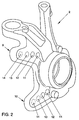
- FIG. 2 shows an axle element for a rear axle, namely a semi-trailing arm 2.
- the pivot bearing 1 has two flanges 3 and 4. These flanges 3 and 4 are like this dimensioned that in them different holes for fastening different Brake caliper sizes can be drilled. In the present case, four can specifically Holes can be provided for four different brake caliper sizes. So can if necessary, either a hole 5 for 15 '' -, a hole 6 for 16 '' -, a hole 7 for 17 '' and a bore 8 for 18 '' brake calipers. As in Fig. 1 recognizable, the holes 5..8 have overlaps. So it always just one of the holes 5..8 drilled. The respective hole 5..8 is therefore in each case immediately before assembly on specific request depending on the intended Brake caliper size drilled. This can be done in a corresponding feed line suitable CNC tool.
- two flanges 9 and 10 are in turn Attachment of brake calipers provided on the semi-trailing arm 2 according to FIG. 2, two flanges 9 and 10 are in turn Attachment of brake calipers provided.
- the flanges 9 and 10 are ear-like molded on the trailing arm 2. They each have four holes 11, 12, 13, 14 for different caliper sizes.
- the holes 11 are for 15 '' brake calipers, bore 12 for 16 '' brake calipers, bore 13 for 17 '' brake calipers and bore 14 for 18 '' calipers. Since the holes 11..14 none Have overlap, all four holes 11..14 can be provided side by side become.
- the holes 11 ..14 are, for example, in one operation be drilled with a drilling tool that has one spindle for each hole 11..14 having. As an alternative, however, only the specifically required bore 11 ..14, as described in connection with the pivot bearing shown in FIG. 1, drilled.
- the pivot bearing 1 also be designed so that several holes in the flange simultaneously can be drilled side by side.
- the flanges 9 and 10 of the semi-trailing arm 2 be dimensioned so that the different holes would be arranged to cover, as described in connection with FIG. 1.
Landscapes
- Engineering & Computer Science (AREA)
- Transportation (AREA)
- Mechanical Engineering (AREA)
- Chemical & Material Sciences (AREA)
- Combustion & Propulsion (AREA)
- Braking Arrangements (AREA)
- Automobile Manufacture Line, Endless Track Vehicle, Trailer (AREA)
Abstract
Description
- Fig. 1
- eine erste Ausführungsform eines Achselements mit den Erfindungsmerkmalen,
- Fig. 2
- eine weitere Ausführungsform eines Achselements mit den Erfindungsmerkmalen.
- 1
- Schwenklage
- 2
- Schräglenker
- 3
- Flansch
- 4
- Flansch
- 5
- Bohrung
- 6
- Bohrung
- 7
- Bohrung
- 8
- Bohrung
- 9
- Flansch
- 10
- Flansch
- 11
- Bohrung
- 12
- Bohrung
- 13
- Bohrung
- 14
- Bohrung
Claims (6)
Applications Claiming Priority (2)
| Application Number | Priority Date | Filing Date | Title |
|---|---|---|---|
| DE19855789 | 1998-12-03 | ||
| DE19855789A DE19855789A1 (de) | 1998-12-03 | 1998-12-03 | Achselement eines Kraftfahrzeugs, insbesondere Schwenklager oder Schräglenker, sowie Verfahren zu deren Herstellung |
Publications (3)
| Publication Number | Publication Date |
|---|---|
| EP1006043A2 true EP1006043A2 (de) | 2000-06-07 |
| EP1006043A3 EP1006043A3 (de) | 2001-02-07 |
| EP1006043B1 EP1006043B1 (de) | 2004-02-18 |
Family
ID=7889847
Family Applications (1)
| Application Number | Title | Priority Date | Filing Date |
|---|---|---|---|
| EP99122536A Expired - Lifetime EP1006043B1 (de) | 1998-12-03 | 1999-11-12 | Achselement-und-Bremssattel-System einer Kraftfahrzeugachse sowie Verfahren zu deren Herstellung |
Country Status (3)
| Country | Link |
|---|---|
| EP (1) | EP1006043B1 (de) |
| AT (1) | ATE259735T1 (de) |
| DE (2) | DE19855789A1 (de) |
Cited By (1)
| Publication number | Priority date | Publication date | Assignee | Title |
|---|---|---|---|---|
| WO2016153988A1 (en) * | 2015-03-20 | 2016-09-29 | Hendrickson Usa, L.L.C. | Steering knuckles with integrated brake mounting provisions |
Family Cites Families (2)
| Publication number | Priority date | Publication date | Assignee | Title |
|---|---|---|---|---|
| DE1845282U (de) * | 1960-07-27 | 1962-01-18 | Henschel Werke G M B H | Halterung fuer bremsen von kraftfahrzeugen. |
| DE29705646U1 (de) * | 1997-03-29 | 1997-05-15 | Braun, Uwe, Dr.-Ing., 47259 Duisburg | Adapter zum Einsatz von Hochleistungsbremszangen |
-
1998
- 1998-12-03 DE DE19855789A patent/DE19855789A1/de not_active Withdrawn
-
1999
- 1999-11-12 DE DE59908576T patent/DE59908576D1/de not_active Expired - Lifetime
- 1999-11-12 EP EP99122536A patent/EP1006043B1/de not_active Expired - Lifetime
- 1999-11-12 AT AT99122536T patent/ATE259735T1/de not_active IP Right Cessation
Non-Patent Citations (1)
| Title |
|---|
| None |
Cited By (1)
| Publication number | Priority date | Publication date | Assignee | Title |
|---|---|---|---|---|
| WO2016153988A1 (en) * | 2015-03-20 | 2016-09-29 | Hendrickson Usa, L.L.C. | Steering knuckles with integrated brake mounting provisions |
Also Published As
| Publication number | Publication date |
|---|---|
| EP1006043B1 (de) | 2004-02-18 |
| ATE259735T1 (de) | 2004-03-15 |
| EP1006043A3 (de) | 2001-02-07 |
| DE59908576D1 (de) | 2004-03-25 |
| DE19855789A1 (de) | 2000-06-08 |
Similar Documents
| Publication | Publication Date | Title |
|---|---|---|
| DE60012012T2 (de) | Herstellungsverfahren einer radnabeneinheit mit minimaler exzentrizität | |
| DE3406327C2 (de) | ||
| EP0641677B1 (de) | Einheitsradsystem für Strassenfahrzeuge | |
| DE10258166A1 (de) | Querlenker für eine verstellbare Aufhängungsbaugruppe | |
| DE2349731A1 (de) | Gelenkteil, insbesondere vorderradaufhaengung von fahrzeugen, und verfahren zu dessen herstellung | |
| DE102012005932B4 (de) | Lageranordnung | |
| DE69826392T2 (de) | Modulartiger schwimmsattel für scheibenbremse | |
| DE102019209930A1 (de) | Aktuator einer steer-by-wire-Lenkung mit einem Spindelantrieb sowie steer-by-wire-Lenkung | |
| EP1006043B1 (de) | Achselement-und-Bremssattel-System einer Kraftfahrzeugachse sowie Verfahren zu deren Herstellung | |
| DE102022104110A1 (de) | Bauteil für eine lenkungsaufhängung eines fahrzeugs | |
| DE2635823A1 (de) | Scheibenbremse | |
| DE102018210636A1 (de) | Aktuatoreinrichtung für ein Kraftfahrzeug sowie Verfahren zu deren Herstellung | |
| DE19841096C1 (de) | Scheibenbremse | |
| DE102007047793A1 (de) | Anordnung zur Befestigung einer Bremsvorrichtung an einem Radträger eines Fahrzeuges | |
| DE102018110576B3 (de) | Einzelradaufhängung für einen Fahrzeuganhänger und Herstellungsverfahren | |
| DE19858243B4 (de) | Bremsscheibe für Scheibenbremsen | |
| DE10202778B4 (de) | Bremsträgeranordnung | |
| DE2235244A1 (de) | Halterung fuer eine detektoreinheit bei blockierschutzanlagen von fahrzeugen | |
| DE69808236T2 (de) | Schraube zur Befestigung eines Fahrzeugrades aus Leichtmetall oder Blech | |
| EP0470527B1 (de) | Schwinghebel-Radlagerung für Fahrzeugachsen | |
| WO1994017380A1 (de) | Anordnung für drehmomentmessungen an kraftfahrzeugen | |
| DE102020000597A1 (de) | Achsschenkel für eine Achse eines Fahrzeugs | |
| DE102017127120A1 (de) | Bremsanordnung für ein Nutzfahrzeug | |
| DE102018004552A1 (de) | Vorrichtung zur Radsturzeinstellung | |
| DE102018132304A1 (de) | Befestigungsanordnung eines Schwingungsdämpfers eines Fahrzeuges |
Legal Events
| Date | Code | Title | Description |
|---|---|---|---|
| PUAI | Public reference made under article 153(3) epc to a published international application that has entered the european phase |
Free format text: ORIGINAL CODE: 0009012 |
|
| AK | Designated contracting states |
Kind code of ref document: A2 Designated state(s): AT BE CH CY DE DK ES FI FR GB GR IE IT LI LU MC NL PT SE |
|
| AX | Request for extension of the european patent |
Free format text: AL;LT;LV;MK;RO;SI |
|
| RIN1 | Information on inventor provided before grant (corrected) |
Inventor name: KUEBLER, ULF Inventor name: SCHULTZ, WERNER |
|
| PUAL | Search report despatched |
Free format text: ORIGINAL CODE: 0009013 |
|
| AK | Designated contracting states |
Kind code of ref document: A3 Designated state(s): AT BE CH CY DE DK ES FI FR GB GR IE IT LI LU MC NL PT SE |
|
| AX | Request for extension of the european patent |
Free format text: AL;LT;LV;MK;RO;SI |
|
| 17P | Request for examination filed |
Effective date: 20010807 |
|
| AKX | Designation fees paid |
Free format text: AT BE CH CY DE DK ES FI FR GB GR IE IT LI LU MC NL PT SE |
|
| 17Q | First examination report despatched |
Effective date: 20020222 |
|
| GRAP | Despatch of communication of intention to grant a patent |
Free format text: ORIGINAL CODE: EPIDOSNIGR1 |
|
| RTI1 | Title (correction) |
Free format text: SYSTEM OF AN AXLE ELEMENT AND CALIPER OF A MOTOR VEHICLE AS WELL AS METHOD OF MAKING THE SAME |
|
| GRAS | Grant fee paid |
Free format text: ORIGINAL CODE: EPIDOSNIGR3 |
|
| GRAA | (expected) grant |
Free format text: ORIGINAL CODE: 0009210 |
|
| AK | Designated contracting states |
Kind code of ref document: B1 Designated state(s): AT BE CH CY DE DK ES FI FR GB GR IE IT LI LU MC NL PT SE |
|
| PG25 | Lapsed in a contracting state [announced via postgrant information from national office to epo] |
Ref country code: NL Free format text: LAPSE BECAUSE OF FAILURE TO SUBMIT A TRANSLATION OF THE DESCRIPTION OR TO PAY THE FEE WITHIN THE PRESCRIBED TIME-LIMIT Effective date: 20040218 Ref country code: IT Free format text: LAPSE BECAUSE OF FAILURE TO SUBMIT A TRANSLATION OF THE DESCRIPTION OR TO PAY THE FEE WITHIN THE PRE;WARNING: LAPSES OF ITALIAN PATENTS WITH EFFECTIVE DATE BEFORE 2007 MAY HAVE OCCURRED AT ANY TIME BEFORE 2007. THE CORRECT EFFECTIVE DATE MAY BE DIFFERENT FROM THE ONE RECORDED.SCRIBED TIME-LIMIT Effective date: 20040218 Ref country code: IE Free format text: LAPSE BECAUSE OF FAILURE TO SUBMIT A TRANSLATION OF THE DESCRIPTION OR TO PAY THE FEE WITHIN THE PRESCRIBED TIME-LIMIT Effective date: 20040218 Ref country code: GB Free format text: LAPSE BECAUSE OF FAILURE TO SUBMIT A TRANSLATION OF THE DESCRIPTION OR TO PAY THE FEE WITHIN THE PRESCRIBED TIME-LIMIT Effective date: 20040218 Ref country code: FI Free format text: LAPSE BECAUSE OF FAILURE TO SUBMIT A TRANSLATION OF THE DESCRIPTION OR TO PAY THE FEE WITHIN THE PRESCRIBED TIME-LIMIT Effective date: 20040218 Ref country code: CY Free format text: LAPSE BECAUSE OF FAILURE TO SUBMIT A TRANSLATION OF THE DESCRIPTION OR TO PAY THE FEE WITHIN THE PRESCRIBED TIME-LIMIT Effective date: 20040218 |
|
| REG | Reference to a national code |
Ref country code: GB Ref legal event code: FG4D Free format text: NOT ENGLISH |
|
| REG | Reference to a national code |
Ref country code: CH Ref legal event code: EP |
|
| REG | Reference to a national code |
Ref country code: IE Ref legal event code: FG4D Free format text: GERMAN |
|
| REF | Corresponds to: |
Ref document number: 59908576 Country of ref document: DE Date of ref document: 20040325 Kind code of ref document: P |
|
| PG25 | Lapsed in a contracting state [announced via postgrant information from national office to epo] |
Ref country code: SE Free format text: LAPSE BECAUSE OF FAILURE TO SUBMIT A TRANSLATION OF THE DESCRIPTION OR TO PAY THE FEE WITHIN THE PRESCRIBED TIME-LIMIT Effective date: 20040518 Ref country code: GR Free format text: LAPSE BECAUSE OF FAILURE TO SUBMIT A TRANSLATION OF THE DESCRIPTION OR TO PAY THE FEE WITHIN THE PRESCRIBED TIME-LIMIT Effective date: 20040518 Ref country code: DK Free format text: LAPSE BECAUSE OF FAILURE TO SUBMIT A TRANSLATION OF THE DESCRIPTION OR TO PAY THE FEE WITHIN THE PRESCRIBED TIME-LIMIT Effective date: 20040518 |
|
| PG25 | Lapsed in a contracting state [announced via postgrant information from national office to epo] |
Ref country code: ES Free format text: LAPSE BECAUSE OF FAILURE TO SUBMIT A TRANSLATION OF THE DESCRIPTION OR TO PAY THE FEE WITHIN THE PRESCRIBED TIME-LIMIT Effective date: 20040529 |
|
| NLV1 | Nl: lapsed or annulled due to failure to fulfill the requirements of art. 29p and 29m of the patents act | ||
| GBV | Gb: ep patent (uk) treated as always having been void in accordance with gb section 77(7)/1977 [no translation filed] |
Effective date: 20040218 |
|
| REG | Reference to a national code |
Ref country code: IE Ref legal event code: FD4D |
|
| ET | Fr: translation filed | ||
| PG25 | Lapsed in a contracting state [announced via postgrant information from national office to epo] |
Ref country code: LU Free format text: LAPSE BECAUSE OF NON-PAYMENT OF DUE FEES Effective date: 20041112 Ref country code: AT Free format text: LAPSE BECAUSE OF NON-PAYMENT OF DUE FEES Effective date: 20041112 |
|
| PG25 | Lapsed in a contracting state [announced via postgrant information from national office to epo] |
Ref country code: MC Free format text: LAPSE BECAUSE OF NON-PAYMENT OF DUE FEES Effective date: 20041130 Ref country code: LI Free format text: LAPSE BECAUSE OF NON-PAYMENT OF DUE FEES Effective date: 20041130 Ref country code: CH Free format text: LAPSE BECAUSE OF NON-PAYMENT OF DUE FEES Effective date: 20041130 Ref country code: BE Free format text: LAPSE BECAUSE OF NON-PAYMENT OF DUE FEES Effective date: 20041130 |
|
| PLBE | No opposition filed within time limit |
Free format text: ORIGINAL CODE: 0009261 |
|
| STAA | Information on the status of an ep patent application or granted ep patent |
Free format text: STATUS: NO OPPOSITION FILED WITHIN TIME LIMIT |
|
| 26N | No opposition filed |
Effective date: 20041119 |
|
| BERE | Be: lapsed |
Owner name: *VOLKSWAGEN A.G. Effective date: 20041130 |
|
| REG | Reference to a national code |
Ref country code: CH Ref legal event code: PL |
|
| BERE | Be: lapsed |
Owner name: *VOLKSWAGEN A.G. Effective date: 20041130 |
|
| PG25 | Lapsed in a contracting state [announced via postgrant information from national office to epo] |
Ref country code: PT Free format text: LAPSE BECAUSE OF NON-PAYMENT OF DUE FEES Effective date: 20040718 |
|
| PGFP | Annual fee paid to national office [announced via postgrant information from national office to epo] |
Ref country code: DE Payment date: 20101130 Year of fee payment: 12 |
|
| PGFP | Annual fee paid to national office [announced via postgrant information from national office to epo] |
Ref country code: FR Payment date: 20111214 Year of fee payment: 13 |
|
| REG | Reference to a national code |
Ref country code: FR Ref legal event code: ST Effective date: 20130731 |
|
| REG | Reference to a national code |
Ref country code: DE Ref legal event code: R119 Ref document number: 59908576 Country of ref document: DE Effective date: 20130601 |
|
| PG25 | Lapsed in a contracting state [announced via postgrant information from national office to epo] |
Ref country code: DE Free format text: LAPSE BECAUSE OF NON-PAYMENT OF DUE FEES Effective date: 20130601 |
|
| PG25 | Lapsed in a contracting state [announced via postgrant information from national office to epo] |
Ref country code: FR Free format text: LAPSE BECAUSE OF NON-PAYMENT OF DUE FEES Effective date: 20121130 |