EP1006045A2 - Stossdämpfer oder teleskopisches Federbein - Google Patents
Stossdämpfer oder teleskopisches Federbein Download PDFInfo
- Publication number
- EP1006045A2 EP1006045A2 EP99120749A EP99120749A EP1006045A2 EP 1006045 A2 EP1006045 A2 EP 1006045A2 EP 99120749 A EP99120749 A EP 99120749A EP 99120749 A EP99120749 A EP 99120749A EP 1006045 A2 EP1006045 A2 EP 1006045A2
- Authority
- EP
- European Patent Office
- Prior art keywords
- cylinder
- shock absorber
- braiding
- chamber
- stem
- Prior art date
- Legal status (The legal status is an assumption and is not a legal conclusion. Google has not performed a legal analysis and makes no representation as to the accuracy of the status listed.)
- Withdrawn
Links
Images

Classifications
-
- F—MECHANICAL ENGINEERING; LIGHTING; HEATING; WEAPONS; BLASTING
- F16—ENGINEERING ELEMENTS AND UNITS; GENERAL MEASURES FOR PRODUCING AND MAINTAINING EFFECTIVE FUNCTIONING OF MACHINES OR INSTALLATIONS; THERMAL INSULATION IN GENERAL
- F16F—SPRINGS; SHOCK-ABSORBERS; MEANS FOR DAMPING VIBRATION
- F16F9/00—Springs, vibration-dampers, shock-absorbers, or similarly-constructed movement-dampers using a fluid or the equivalent as damping medium
- F16F9/10—Springs, vibration-dampers, shock-absorbers, or similarly-constructed movement-dampers using a fluid or the equivalent as damping medium using liquid only; using a fluid of which the nature is immaterial
- F16F9/14—Devices with one or more members, e.g. pistons, vanes, moving to and fro in chambers and using throttling effect
- F16F9/16—Devices with one or more members, e.g. pistons, vanes, moving to and fro in chambers and using throttling effect involving only straight-line movement of the effective parts
- F16F9/18—Devices with one or more members, e.g. pistons, vanes, moving to and fro in chambers and using throttling effect involving only straight-line movement of the effective parts with a closed cylinder and a piston separating two or more working spaces therein
-
- B—PERFORMING OPERATIONS; TRANSPORTING
- B62—LAND VEHICLES FOR TRAVELLING OTHERWISE THAN ON RAILS
- B62K—CYCLES; CYCLE FRAMES; CYCLE STEERING DEVICES; RIDER-OPERATED TERMINAL CONTROLS SPECIALLY ADAPTED FOR CYCLES; CYCLE AXLE SUSPENSIONS; CYCLE SIDECARS, FORECARS, OR THE LIKE
- B62K25/00—Axle suspensions
- B62K25/04—Axle suspensions for mounting axles resiliently on cycle frame or fork
- B62K25/06—Axle suspensions for mounting axles resiliently on cycle frame or fork with telescopic fork, e.g. including auxiliary rocking arms
-
- F—MECHANICAL ENGINEERING; LIGHTING; HEATING; WEAPONS; BLASTING
- F16—ENGINEERING ELEMENTS AND UNITS; GENERAL MEASURES FOR PRODUCING AND MAINTAINING EFFECTIVE FUNCTIONING OF MACHINES OR INSTALLATIONS; THERMAL INSULATION IN GENERAL
- F16F—SPRINGS; SHOCK-ABSORBERS; MEANS FOR DAMPING VIBRATION
- F16F9/00—Springs, vibration-dampers, shock-absorbers, or similarly-constructed movement-dampers using a fluid or the equivalent as damping medium
- F16F9/06—Springs, vibration-dampers, shock-absorbers, or similarly-constructed movement-dampers using a fluid or the equivalent as damping medium using both gas and liquid
- F16F9/08—Springs, vibration-dampers, shock-absorbers, or similarly-constructed movement-dampers using a fluid or the equivalent as damping medium using both gas and liquid where gas is in a chamber with a flexible wall
- F16F9/084—Springs, vibration-dampers, shock-absorbers, or similarly-constructed movement-dampers using a fluid or the equivalent as damping medium using both gas and liquid where gas is in a chamber with a flexible wall comprising a gas spring contained within a flexible wall, the wall not being in contact with the damping fluid, i.e. mounted externally on the damper cylinder
-
- F—MECHANICAL ENGINEERING; LIGHTING; HEATING; WEAPONS; BLASTING
- F16—ENGINEERING ELEMENTS AND UNITS; GENERAL MEASURES FOR PRODUCING AND MAINTAINING EFFECTIVE FUNCTIONING OF MACHINES OR INSTALLATIONS; THERMAL INSULATION IN GENERAL
- F16F—SPRINGS; SHOCK-ABSORBERS; MEANS FOR DAMPING VIBRATION
- F16F2230/00—Purpose; Design features
- F16F2230/10—Enclosure elements, e.g. for protection
Definitions
- the present invention relates to shock absorbers and to telescopic suspensions in general, both hydraulic and hydropneumatic, equipped with a compensator to compensate the various volume changes in the chambers placed opposite the piston in the telescopic system when one of such chambers is engaged by a stem fastened to the piston of the telescopic system.
- the compensator is connected to one of the inside chambers of the telescopic system, usually to the one with the larger volume.
- compensators are mounted at the interior and on the bottom of said chamber with the larger volume, with the inconvenience of increasing the overall length of the telescopic system, and more often they are placed outside, laterally or even in a distant position from the telescopic system itself, with a flexible pipe representing the connection to said chamber with the larger volume.
- Compensators of the known type substantially consist of a chamber divided into two portions by a piston with lateral seal, or by a membrane made of flexible and possibly elastic material, one portion of said chamber being filled with oil and connected to the chamber with the larger volume of the telescopic system, whereas the other chamber portion is usually occupied by a pressurised gas, whose pressure is often adjustable, so as to ensure a rapid return of the oil from the compensator back to the inner circuit of the telescopic system when the latter is making the extension stroke, also to avoid cavitation phenomena within said circuit. From above it results that compensators of the known type substantially involve a problem of space and they normally require a pressurisation chamber opposite to the one occupied by the oil.
- At least one tubular, flexible and preferably elastic, impermeable and oil-resistant braiding is fitted on the outside lateral surface of the cylinder in the telescopic system, said braiding being seal-fastened with its ends onto said cylinder, for instance by means of bands or other suitable means, so as to form at its interior a compensation chamber with changing volume, said chamber being connected to at least one of the inner chambers of the telescopic system, for instance to the chamber with the larger volume, by means of holes on the ends of said chamber.
- the compensator thus obtained presents extremely limited overall dimensions and does not require a pressurisation from outside since its emptying is substantially helped by the elastic memory of the braiding which forms same.
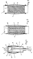
- the numeral 1 indicates the cylinder of a shock absorber, closed at one end and containing a piston 2 connected to a stem 3 which comes out of the other end of the cylinder 1 axially and with lateral seal, said piston running with lateral seal within the cylinder.
- the numerals 4 and 5 indicate the attachments of the shock absorber with two points of the mechanism to be cushioned, said points being usually reciprocally urged apart by elastic means, not shown here, so that the shock absorber in its rest position shows the stem 3 extending from the cylinder 1.
- the inside chambers A and B of the cylinder 1, defined by the opposite sides of the piston 2, are filled with oil or of any other suitable liquid, and on the piston 2 valve means of any suitable type, also differing from those schematically indicated with the numeral 6, are provided, said means being possibly adjustable and controlling the passage of oil between the chambers A and B during the extension and retraction stroke of the stem 3, so as to ensure the necessary cushioning of the stresses to which the telescopic system is subjected.
- the present invention provides, for instance, lateral holes 7 on the base of the chamber with the larger volume A and, mounted outside the cylinder 1, an impermeable braiding 8, said braiding being flexible and preferably made of any suitable, elastomeric and oil-resistant material, having suitable length and thickness and being seal-fastened by its ends onto the cylinder 1, for instance with centripetal clamping means 9 and 10, for instance with bands or groups of cone-shaped rings with different hardness, whose contact surfaces are provided with anti-unthreading grooves (Fig.
- the braiding 8 and the outside wall of the cylinder 1 onto which said braiding is placed form together a compensation chamber C sealed outwards, which can change in volume because of the flexibility and elasticity of said braiding 8 and which communicates with the chamber A of the shock absorber through the holes 7.
- the chamber C is filled with oil. In particular, when the stem 3 is in its extended or rest position, the chamber C presents the smallest volume.
- the holes 7 open into an outside ring-shaped recess 107 of the cylinder 1 and it can also be provided that into such recess small grooves open, said grooves taking up the whole length or part of the outside surface of the cylinder 1 forming said chamber C, for instance small rectilinear grooves 11 as shown in Figure 2 or small helicoidal grooves 12 as shown in Figure 3.
- the longitudinal grooves 11 or 12 can also be provided onto an intermediate portion of the inside lateral surface of the braiding 8.
- the outside lateral surface of the cylinder 1 is suitably conically shaped in the portion which forms the chamber C, or it can be provided that the braiding 8 is carried out with a different elasticity along its length, so as to avoid that during its elastic contraction the braiding 8 blocks the holes 7, at least until the chamber C becomes empty.
- the braiding 8 has to be used for shock absorbers or telescopic systems where it could be visible, it can be provided for means to protect the diaphragm itself, for instance by means of a flexible sheath, possibly bellows-like, made of any material suitable for this purpose.
- the numeral 13 indicates the sheath or outer sliding tube, that is, the tubular element with the larger section of the leg, said sheath being closed on its upper end by means of a plug 14 and containing the tubular stem or inner sliding tube 15 running telescopically within the sheath, said tubular stem 15 being closed on its lower end by means of a plug 16 and being provided with the extension 5 for the connection with the wheel axis.
- the sheath 13 is provided on its lower end with a sealing system 17 and with a guiding ring 117 with an inside diameter which is smaller than the diameter of the sheath itself, said guiding ring containing the stem 15 running within it with lateral seal, said stem 15 being provided on its upper end with an outside ring 18 sliding with seal on the lateral surface of the sheath itself, so that the running surface for the portions 13 and 15 is limited to the surface of the rings 117 and 18 and so that there is a ring-shaped chamber D between the two portions, said chamber D communicating constantly with the inside chamber E of the telescopic system 13, 15 through the holes 19 obtained on the upper end of the stem 15 under the sliding ring 18.
- the chamber D can freely suck up or let out air from or into chamber E and it can receive a small amount of oil for the lubrication of the relatively movable surfaces of the portions 13 and 15 from said chamber E.
- the chamber E of the leg is partly occupied by the lubricating oil, preferably of the high-density type, which can reach the holes 19 with the periodical overturning of the fork and because of the emulsification of the oil itself with the air contained in the chamber E.
- the plug 14 closes the end of the cylinder 1 of a shock absorber as described in Figure 1, placed, within the telescopic system 13, 15, coaxially with the stem 3 which may be oriented in the same direction as the stem 15 and integral with the group formed by the plug 16 together with the coupling 5.
- adjusting means can be provided, which are not shown here since they have no influence for the understanding of the present invention, to adjust the valve means 6 placed on the piston 2 of the shock absorber.
- Other adjusting means which are not shown either, can be provided on the plug 14, whose purpose is to adjust possible valve means placed within the chamber A of the shock absorber, said means not being shown either, whose purpose is to adjust the position of the fork formed by said legs, during both the compression and the extension stage.
- the fork leg is completed by the holes 7 together with the outside ring-shaped recess 107 on the upper end of the cylinder 1 and the impermeable, flexible and elastic braiding 8 outside said cylinder 1, fastened with its ends onto said cylinder by means of the clamping elements 9 and 10.
- the braiding is shaped in such a way as not to interfere with the upper end of the sheath 15 of the telescopic shaft.
- the chambers A, B and C of the shock absorber are filled with a low-viscosity liquid, which is sufficiently stable to changes in the fork operating temperature. Thanks to the braiding 8 the lubricating oil located in chamber E of the telescopic system 13, 15 will never mix with the oil in the circuit of the shock absorber cartridge.
- An elastic means 20 consisting for instance of a spring or of a group of elastomer elements is provided within the stem 15, outside the stem 3 of the shock absorber, bearing with one end onto the bottom of the stem 15 and with the other end onto a cup 101 of the cylinder 1, so as to urge to extension the fork leg.
- the fork shaft shown in Figures 4 and 5 can also be reversed, that is to say, with the stem 15 oriented upwards and connected to the bike handlebar and with the sheath 13 oriented downwards and connected to the wheel axis of the bike itself, thus resulting in a better lubrication of the portions 13, 15, even with a small amount of oil within the chamber E.
- shock absorber equipped with the compensator can be fitted into the telescopic system 13, 15 with a reversed orientation with respect to the orientation shown in Figures 4 and 5. Finally, it is evident how the pressure within chamber E of the fork improves the elastic recovery of the braiding 8 and how it can even allow the use of a braiding whose only feature is flexibility.
Landscapes
- Engineering & Computer Science (AREA)
- General Engineering & Computer Science (AREA)
- Mechanical Engineering (AREA)
- Fluid-Damping Devices (AREA)
- Vibration Dampers (AREA)
Applications Claiming Priority (2)
| Application Number | Priority Date | Filing Date | Title |
|---|---|---|---|
| IT1998BO000684A IT1304247B1 (it) | 1998-12-03 | 1998-12-03 | Ammortizzatore o sospensione telescopica, di tipo idraulico odidropneumatico, con compensatore incorporato, a basso ingombro, di |
| ITBO980684 | 1998-12-03 |
Publications (2)
| Publication Number | Publication Date |
|---|---|
| EP1006045A2 true EP1006045A2 (de) | 2000-06-07 |
| EP1006045A3 EP1006045A3 (de) | 2001-05-23 |
Family
ID=11343552
Family Applications (1)
| Application Number | Title | Priority Date | Filing Date |
|---|---|---|---|
| EP99120749A Withdrawn EP1006045A3 (de) | 1998-12-03 | 1999-10-20 | Stossdämpfer oder teleskopisches Federbein |
Country Status (3)
| Country | Link |
|---|---|
| US (2) | US6557674B2 (de) |
| EP (1) | EP1006045A3 (de) |
| IT (1) | IT1304247B1 (de) |
Cited By (1)
| Publication number | Priority date | Publication date | Assignee | Title |
|---|---|---|---|---|
| US6543799B2 (en) | 2000-01-13 | 2003-04-08 | Shimano Inc. | Bicycle suspension |
Families Citing this family (8)
| Publication number | Priority date | Publication date | Assignee | Title |
|---|---|---|---|---|
| US6695104B2 (en) * | 2000-12-27 | 2004-02-24 | Osman Akad | Reusable impact energy absorbing device |
| US6695105B2 (en) * | 2001-09-12 | 2004-02-24 | Kayaba Industry Co., Ltd. | Hydraulic shock absorber |
| US7921974B2 (en) * | 2005-11-29 | 2011-04-12 | Fox Factory, Inc. | Damping cylinder with annular bladder |
| DE102010020524A1 (de) * | 2010-05-14 | 2011-11-17 | Dr. Ing. H.C. F. Porsche Aktiengesellschaft | Restdruckhalteventil und Federbein |
| US9926746B2 (en) | 2013-06-19 | 2018-03-27 | Smith International, Inc. | Actuating a downhole tool |
| US20160288306A1 (en) * | 2015-04-06 | 2016-10-06 | Caterpillar Inc. | Hydraulic hammer having self-contained gas spring |
| CN113883106B (zh) * | 2021-10-12 | 2022-06-03 | 燕山大学 | 自变容弹性液压油箱及其控制方法 |
| DE102024118559A1 (de) * | 2024-07-01 | 2026-01-08 | Stabilus Gmbh | Dämpfer mit Bypass, Verfahren zur Herstellung des Dämpfers |
Family Cites Families (25)
| Publication number | Priority date | Publication date | Assignee | Title |
|---|---|---|---|---|
| BE459380A (de) * | 1944-04-14 | |||
| US2571279A (en) * | 1949-06-03 | 1951-10-16 | Nils O Myklestad | Shock absorber |
| DE932949C (de) | 1950-09-07 | 1955-09-12 | Albert Dillenburger | Hydraulischer Teleskop-Stossdaempfer, insbesondere fuer Kraftfahrzeuge |
| FR1060812A (fr) | 1951-11-19 | 1954-04-06 | Amortisseurs hydrauliques télescopiques de suspension | |
| FR1056116A (fr) | 1951-12-07 | 1954-02-24 | Amortisseurs hydrauliques télescopiques thermostatiques de suspensions | |
| FR1076192A (fr) | 1953-02-13 | 1954-10-25 | Blaw Knox Cie Fse | Perfectionnements aux appareils à fluide tels que vérins, accumulateurs d'énergie, ou amortisseurs par exemple |
| US2802664A (en) * | 1955-04-11 | 1957-08-13 | Gen Motors Corp | Hydro-pneumatic suspension unit |
| NL282090A (de) * | 1959-06-20 | |||
| US3052328A (en) * | 1960-01-27 | 1962-09-04 | Smith Corp A O | Hydraulic decelerating device |
| US3039760A (en) * | 1960-08-30 | 1962-06-19 | Gen Motors Corp | Shock absorber and air spring unit assembly |
| US3392849A (en) * | 1966-03-28 | 1968-07-16 | Pullman Inc | Railway hydraulic cushioning device |
| US3556268A (en) * | 1969-01-09 | 1971-01-19 | Moog Industries Inc | Gas controlled orifice in hydraulic shock absorber |
| SE367158B (sv) * | 1971-07-14 | 1974-05-20 | Bilstein August Fa | Hydraulisk stotfaangare |
| US3771626A (en) * | 1972-04-04 | 1973-11-13 | Monroe Auto Equipment Co | Pressurized shock absorber |
| DE2237914A1 (de) * | 1972-08-02 | 1974-02-21 | Bilstein August Fa | Stossdaempfer |
| US3874485A (en) * | 1972-05-01 | 1975-04-01 | Gen Motors Corp | Oleo-pneumatic shock absorber |
| FR2233529B1 (de) * | 1973-06-18 | 1977-02-11 | Inst Francais Du Petrole | |
| US4257499A (en) * | 1977-03-30 | 1981-03-24 | Deschner Richard E | Hydraulic cartridge for improved motion control |
| US4257314A (en) | 1977-03-30 | 1981-03-24 | Deschner Richard E | Apparatus for improved motion control |
| US4226408A (en) * | 1978-02-01 | 1980-10-07 | Honda Giken Kogyo Kabushiki Kaisha | Hydraulic shock absorber for vehicles |
| JPS5624238A (en) | 1979-08-01 | 1981-03-07 | Nissan Motor Co Ltd | Shock absorber |
| DE4025255A1 (de) | 1990-08-09 | 1992-02-13 | Hemscheidt Maschf Hermann | Kolbenzylinderanordnung mit den zylinder umschliessendem ausgleichsraum |
| US5295563A (en) * | 1993-03-01 | 1994-03-22 | General Motors Corporation | Active suspension actuator with control flow through the piston rod |
| JPH10238582A (ja) | 1996-12-27 | 1998-09-08 | Showa:Kk | 油圧緩衝器及び油圧緩衝器への作動油充填方法 |
| DE19723347C1 (de) * | 1997-06-04 | 1998-12-17 | Mannesmann Sachs Ag | Federbein für Fahrzeuge |
-
1998
- 1998-12-03 IT IT1998BO000684A patent/IT1304247B1/it active
-
1999
- 1999-09-30 US US09/409,112 patent/US6557674B2/en not_active Expired - Lifetime
- 1999-10-20 EP EP99120749A patent/EP1006045A3/de not_active Withdrawn
-
2000
- 2000-02-25 US US09/409,112 patent/US20020060111A1/en active Granted
Non-Patent Citations (1)
| Title |
|---|
| None |
Cited By (6)
| Publication number | Priority date | Publication date | Assignee | Title |
|---|---|---|---|---|
| US6543799B2 (en) | 2000-01-13 | 2003-04-08 | Shimano Inc. | Bicycle suspension |
| US6595537B2 (en) | 2000-01-13 | 2003-07-22 | Shimano Inc. | Bicycle suspension |
| US6612599B2 (en) | 2000-01-13 | 2003-09-02 | Shimano Inc. | Bicycle suspension |
| US6619684B2 (en) | 2000-01-13 | 2003-09-16 | Shimano Inc. | Bicycle suspension |
| US6698780B2 (en) | 2000-01-13 | 2004-03-02 | Shimano Inc. | Bicycle suspension |
| US6863291B2 (en) | 2000-01-13 | 2005-03-08 | Shimano, Inc. | Bicycle suspension |
Also Published As
| Publication number | Publication date |
|---|---|
| ITBO980684A0 (it) | 1998-12-03 |
| IT1304247B1 (it) | 2001-03-13 |
| US6557674B2 (en) | 2003-05-06 |
| ITBO980684A1 (it) | 2000-06-03 |
| US20020060111A1 (en) | 2002-05-23 |
| EP1006045A3 (de) | 2001-05-23 |
Similar Documents
| Publication | Publication Date | Title |
|---|---|---|
| US8794404B2 (en) | Hydraulic shock absorber | |
| US8342488B2 (en) | Damping cylinder with annular bladder | |
| US3752498A (en) | Oleo-pneumatic suspension assembly | |
| AU2003203440B2 (en) | Suspension system | |
| EP2272693A2 (de) | Luftfederanordnung auf einem Dämpfer bei Anwendung von einer Dichtung | |
| EP1006045A2 (de) | Stossdämpfer oder teleskopisches Federbein | |
| EP3163114B1 (de) | Dämpfer | |
| US3524658A (en) | Shock absorbers | |
| US6511085B2 (en) | Vehicle suspension apparatus | |
| US20040262107A1 (en) | Shock absorber having a pressurized gas compartment | |
| US3954256A (en) | Suspension system for automotive vehicles and the like | |
| EP3594528B1 (de) | Suspension | |
| US3497198A (en) | Shock absorber and air spring assembly | |
| US20230018887A1 (en) | Telescopic passive damper | |
| US4921226A (en) | Lined air sleeve assembly for air spring damper | |
| JP4022649B2 (ja) | 油圧緩衝器 | |
| US6651547B2 (en) | Guide for the piston rod of a piston-cylinder assembly | |
| US4189034A (en) | Hydraulic damper | |
| GB2057089A (en) | Hydraulic shock absorber with compensating chamber | |
| CN102388233A (zh) | 多筒型液压缓冲器 | |
| IT201800003955A1 (it) | Molla pneumatica | |
| JPH0249407Y2 (de) | ||
| JP5202426B2 (ja) | 緩衝器 | |
| EP4170195B1 (de) | Teleskopischer passiver dämpfer | |
| GB1566021A (en) | Loadbearing telescopic leg |
Legal Events
| Date | Code | Title | Description |
|---|---|---|---|
| PUAI | Public reference made under article 153(3) epc to a published international application that has entered the european phase |
Free format text: ORIGINAL CODE: 0009012 |
|
| AK | Designated contracting states |
Kind code of ref document: A2 Designated state(s): AT BE CH CY DE DK ES FI FR GB GR IE IT LI LU MC NL PT SE |
|
| AX | Request for extension of the european patent |
Free format text: AL;LT;LV;MK;RO;SI |
|
| PUAL | Search report despatched |
Free format text: ORIGINAL CODE: 0009013 |
|
| AK | Designated contracting states |
Kind code of ref document: A3 Designated state(s): AT BE CH CY DE DK ES FI FR GB GR IE IT LI LU MC NL PT SE |
|
| AX | Request for extension of the european patent |
Free format text: AL;LT;LV;MK;RO;SI |
|
| AKX | Designation fees paid | ||
| REG | Reference to a national code |
Ref country code: DE Ref legal event code: 8566 |
|
| STAA | Information on the status of an ep patent application or granted ep patent |
Free format text: STATUS: THE APPLICATION IS DEEMED TO BE WITHDRAWN |
|
| 18D | Application deemed to be withdrawn |
Effective date: 20011124 |