EP1006236B1 - Beheizbare Kalanderwalze - Google Patents
Beheizbare Kalanderwalze Download PDFInfo
- Publication number
- EP1006236B1 EP1006236B1 EP19990122637 EP99122637A EP1006236B1 EP 1006236 B1 EP1006236 B1 EP 1006236B1 EP 19990122637 EP19990122637 EP 19990122637 EP 99122637 A EP99122637 A EP 99122637A EP 1006236 B1 EP1006236 B1 EP 1006236B1
- Authority
- EP
- European Patent Office
- Prior art keywords
- displacement member
- roller according
- calender roller
- calender
- plastic
- Prior art date
- Legal status (The legal status is an assumption and is not a legal conclusion. Google has not performed a legal analysis and makes no representation as to the accuracy of the status listed.)
- Expired - Lifetime
Links
Images

Classifications
-
- D—TEXTILES; PAPER
- D21—PAPER-MAKING; PRODUCTION OF CELLULOSE
- D21G—CALENDERS; ACCESSORIES FOR PAPER-MAKING MACHINES
- D21G1/00—Calenders; Smoothing apparatus
- D21G1/02—Rolls; Their bearings
- D21G1/0253—Heating or cooling the rolls; Regulating the temperature
- D21G1/0266—Heating or cooling the rolls; Regulating the temperature using a heat-transfer fluid
-
- D—TEXTILES; PAPER
- D21—PAPER-MAKING; PRODUCTION OF CELLULOSE
- D21G—CALENDERS; ACCESSORIES FOR PAPER-MAKING MACHINES
- D21G1/00—Calenders; Smoothing apparatus
- D21G1/02—Rolls; Their bearings
Definitions
- the invention relates to a calender roll which can be heated by means of a heating medium, especially for smoothing or calendering, with a hollow cylindrical, a provided in a central bore of the roller body displacement having roll body and flanged on both sides, him carrying flange.
- Such calender rolls are used, for example, for smoothing or calendering of Paper used in calenders cf. DE 30 14 891A.
- An effective, even heating of the Surface of the roll body can be through a variety of peripheral holes reach, which are penetrated by the heating medium. But you also have the inner jacket heated the roller body and by fitting a displacer the resulting gap in front of the inner shell so concentrated that a good Heat transfer securing flow rates can be achieved. But Even with the use of peripheral drilling is often already for the sake of Weight saving of the roller body bored central, since the loss of central, Neutral phase, although the weight is reduced, but the load capacity only slightly reduces. This leaves a filling of the cavity of the Roller body with the heating medium or blocks it against the heating medium from.
- the invention is based on the task of internals for the central bore of a To provide roll body of heatable calender rolls, which criticized Do not have disadvantages of the usual displacement body.
- Prosoft and Optiload with Surface temperatures between 70 and about 135 ° C can be the displacer Made of conventional plastics, and only for rolls for soft calender with up to 200 ° C surface temperature, the choice is special, more thermoresistant Plastics required.
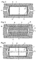
- a heatable calender roll is shown, the hollow cylindrical Roll body 1 is supported by flanged on both sides flange 2.
- the roller body is provided with a number of peripheral holes 3 for the passage of equipped with heating medium and, for example, to reduce the total weight, provided with a central bore 4 of larger diameter.
- the supply of the heating medium and its return takes place by a on End of the flange 2 provided two-piece connection head 5; But it is also possible, the end of each of the flange 2 with a to provide one-piece connection head.
- the central bore 4 of the roller body 1 is provided with a displacement body 6 equipped, which is made of solid plastic.
- This made of plastic Displacer 6 can already firmly by simply pressing be connected to the roller body 1. It has proven itself, the displacement body not about its overall length with the same, the inner diameter the outer diameter of the central bore 4, but this diameter provided for the press fit only certain Length sections 7 comply and between these the outside diameter of Reduce displacer 6 slightly.
- the Displacer 6 in a number individually and successively guidedpressender Be divided into sections.
- the lateral surface of the illustrated roller body is coated with a coating 8 Plastic equipped.
- the reflux of the heating medium to the connector 5 can be a simple Bore 9 can be effected; if necessary, this may, if necessary, by a Be booked up pipe. But it is also possible, the reflux of the heating medium in the area of one or more grooves 10, which are axially parallel, in Shape of turns, helical or the like, along the surface of the displacer 6 can draw. With appropriate design the groove they can be used to heat the inner shell of the roll body become. By reduction of its cross section in the flow direction of the heating medium can the effect of increasing cooling in the flow direction be compensated. If necessary in connection with peripheral bores or only for these can arbitrary flow schemes be realized, e.g. two parallel lines in series with another.
- the easy processability of the plastic also allows economical installation from special installations to. This is especially true for steam-heated rolls axial or axially parallel steam supply holes for the opposite side of the roller body be arranged in the plastic displacement body as well as axial or axially parallel condensate drainage holes.
- the displacement body can be provided with corresponding, preferably recessed grooves respectively radially encircling grooves at the ends of the displacer 6 equipped Nutein loftungen have proven to be in the ends of the Central bore 4 of the roll body.
- peripheral holes 3 with the heating medium can be in predetermined group schemes by additional design of the displacer 6 or at least its ends Achieve:
- the easy workability as noticeable as the low specific weight of the plastic which facilitates balancing work or unnecessary.
- the displacer and the internals can also be multi-part be produced by pressing fit, screwing, tapping, gluing, Welding, etc. are connected.
- a calender roll is shown, the hollow cylindrical roller body 11 is performed without peripheral drilling.
- the roller body is equipped with a displacement body 12 equipped, which is designed as a hollow body and a Plastic tube 13 is completed on both sides by plastic flanges 14 is.
- the inner shell of the roller body 11 and / or the shell of the displacement body 12 are provided with grooves 15 so that this groove 15 passed Heating medium contacted the inner shell of the roller body 11 directly and can give off this heat.
- a coulter could be more parallel to the axis Nute be arranged as they are shown in the manner of a settlement in Figure 4; In general, however, you will be a number in the manner of a multi-thread intertwined multi-course helical groove provide.
- both Flange pin to equip each with a one-piece connection head.
- a varied heatable calender roll 16 is shown, which with a solid plastic displacement body 17 is provided, the expedient of closed-cell Foamed plastic is created. Again, extend the channels forming grooves 15 useful helically, and according to the Throughput, the heating medium collects in the space 18 and flows through a central Bore 9 of the displacer 17 from, in the end of a pipe socket 19th is on the other hand but also over the entire length of the bore can extend.
- the return serving hole can be omitted are when the displacer 17 according to the schematic view 6 is executed and has grooves 20 and 21, which are in the manner of a sauté linen are arranged, and at the left end of the displacer 17 either end in a short ring or in any other way connected to each other.
- groove 20 a first channel is formed, in which the heating medium helically to the opposite End of the displacer 17 and thus the heated body to be heated is guided, and from this end then the heating medium in the through Nut 21 formed channel returned. Since one inlet each - a drainage channel is guided adjacent, this already results in a certain adjustment of the effect the inlet to the outlet temperature. But this alignment can be continue to drive by, as in the enlarged portions of Fig. 7a and 7b, the groove cross-sections are reduced in the flow direction such that the resulting different flow rates required Change the heat transfer coefficients cause.
- FIG. 8 once again shows a varied calender roll which is in the line guide 5 corresponds to the displacement body 12, however, like that of the Fig. 3, is executed hollow for further weight reduction. In this case, if a return via a space 18 is desired, it is necessary that the Pipe socket 19 of FIG. 5 by an entire displacement body 12 and the Flange 2 to replace 2 continuous pipe.
- FIG. 9 For example, are for the passage of the Heating medium mutually parallel groove 15 of the plastic tube 13 of the Fig. 3 used.
- FIG. 10 the return line of the heating medium causing groove 35 of the displacer shown with greater width than those causing the forwarding Nute 33 and 34.
- systems such as those of FIG. 11 can be created, in which by three grooves 26, 27, which are operated in series, a doubly coiled channel is created at the different flow rates again by different groove widths and / or depths are achievable.
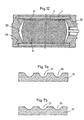
- a heatable calender roll is shown interrupted, that of the Fign. 1 and 2 corresponds to:
- the roller body 1 is peripheral Holes 3 equipped.
- an additional heating is considered:
- the heating medium rises in holes 28 to the peripheral holes. 3 it exits through drain holes 29, reaches the room 30 and then flows by grooves 31 of the plastic displacer 6, which create channels after are bounded outside by surfaces of the inner shell of the roll body 1, so that here a renewed heating, for example.
- a renewed heating for example.
Landscapes
- Paper (AREA)
- Casting Or Compression Moulding Of Plastics Or The Like (AREA)
- Rolls And Other Rotary Bodies (AREA)
- Treatment Of Fiber Materials (AREA)
Description
- Figur 1
- einen Längsschnitt durch eine periphere Bohrungen aufweisenden Kalanderwalze,
- Figur 2
- einen Querschnitt durch die Kalanderwalze nach Fig. 1,
- Figur 3
- einen Längsschnitt durch eine Kalanderwalze, deren aus Kunststoff bestehender Verdrängerkörper durch ein beidseitig durch Flansche geschlossenes Kunststoffrohr gebildet ist, dessen Mantel mit vom Heizmedium durchfließbaren Nuten ausgestattet ist,
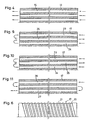
- Figur 4
- schematisch einen abgewickelten Abschnitt des Mantels eines Verdrängerkörpers mit vom Heizmedium durchsetzte Nute in zur Vereinfachung der Darstellung gewählter achsparalleler Anordnung,
- Figur 5
- eine Kalanderwalze mit einstückig aus Kunststoff erstelltem Verdrängerkörper für einen Zweiweg-Anschlußkopf,
- Figur 6
- schematisch einen Verdrängerkörper mit in Form einer zweigängigen Schraubenlinie angelegtem Nut zur Leitung des Heizmediums, wobei die beiden Nute an ihrem linksseitigen Ende ineinander übergehen und ihre rechtsseitigen Enden mit einem Zweiwege-Anschlußkopf zu verbinden sind,
- Figur 7a, b
- Ausschnitte eines Vertikalschnitts der Figur 6,
- Figur 8
- eine der der Fig. 5 wirkungsähnliche Kalanderwalze mit aus Mantel und Deckplatten bestehenden Verdrängerkörper und einem ihn durchstoßenden Rohr,
- Fign. 9 -11
- in der Darstellung der Fig. 4 weitere Leitungsschemata von durch Nute gebildeten Flußwegen des Thermomediums, und
- Figur 12
- nochmals eine periphere Bohrungen aufweisende Kalanderwalze mit Rückleitung des Heizmediums im zwischen dem Walzenmantel und der Verdrängerkörper gebildeten Spalt oder durch Nute gebildeten Kanälen.
Claims (13)
- Mittels eines Heizmediums beheizbare Kalanderwalze, insbesondere zur Glättung oder Satinage, mit einem hohlzylindrischen, einen in einer zentralen Bohrung (4) des Walzenkörpers (1) vorgesehenen Verdrängerkörper (6,12,17) aufweisenden Walzenkörper (1) und an diesen beidseitig angeflanschten, ihn tragenden Flanschzapfen (2),
dadurch gekennzeichnet, daß der Verdrängerkörper (6, 12, 17) aus einem Werkstoff besteht, der spezifisch leichter als der Werkstoff des Walzenkörpers (1) ist. - Kalanderwalze nach Anspruch 1,
dadurch gekennzeichnet, daß der Verdrängerkörper (6, 12, 17) aus einem Werkstoff besteht, der spezifisch leichter als das Heizmedium ist. - Kalanderwalze nach Anspruch 1 oder 2,
dadurch gekennzeichnet, daß der Verdrängerkörper (6, 17) aus Kunststoff, vorzugsweise aus massivem Kunststoff besteht. - Kalanderwalze nach Ansprüchen 1 bis 3,
dadurch gekennzeichnet, daß der Verdrängerkörper (6, 12, 17) aus vorzugsweise geschlossene Poren aufweisenden Schaumkunststoff besteht. - Kalanderwalzen nach Ansprüchen 1 bis 4,
dadurch gekennzeichnet, daß der Verdrängerkörper (6, 17) mindestens eine zentrale Bohrung (9) aufweist. - Kalanderwalzen nach Ansprüchen 1 bis 5,
dadurch gekennzeichnet, daß der Verdrängerkörper (6, 12, 17) mit mindestens einer sich entlang seines Umfanges erstreckenden Nut (10, 15, 20, 21, 23, 24, 25, 26, 27, 33, 34, 35) ausgestattet ist. - Kalanderwalze nach Anspruch 6,
gekennzeichnet durch
schraubenlinienförmig verlaufende Nute (20, 21, 31). - Kalanderwalze nach Anspruch 6,
gekennzeichnet durch
entlang von Mantellinien oder schräg gegen diese verlaufende Nute (9, 15, 31). - Kalanderwalze nach Ansprüchen 1 bis 8,
dadurch gekennzeichnet, daß der Außendurchmesser des Verdrängerkörpers (6) einen Preßsitz in der zentralen Bohrung (4) sichert. - Kalanderwalze nach Anspruch 9,
dadurch gekennzeichnet, daß der Außendurchmesser des Verdrängerkörpers (6) nur über mehrere Längenabschnitte (7) der zentralen Bohrung (4) des Walzenkörpers (1) angepaßt ist und zwischen diesen zurücktritt. - Kalanderwalze nach Ansprüchen 1 bis 10,
dadurch gekennzeichnet, daß der Verdrängerkörper (6) in Längsrichtung in einzelne Schüsse unterteilt ist. - Kalanderwalze nach Ansprüchen 1 bis 11,
dadurch gekennzeichnet, daß der Verdrängerkörper (12) oder ihn bildende Schüsse als Kunststoff-Hohlkörper ausgebildet sind. - Kalanderwalze nach Ansprüchen 1 bis 12,
dadurch gekennzeichnet, daß der Verdrängerkörper (6) mehrteilig aufgebaut ist und unterschiedlichen Zwecken angepaßte Ausnehmungen aufweist.
Applications Claiming Priority (4)
| Application Number | Priority Date | Filing Date | Title |
|---|---|---|---|
| DE19854522 | 1998-11-26 | ||
| DE19854522 | 1998-11-26 | ||
| DE19950645A DE19950645A1 (de) | 1998-11-26 | 1999-10-21 | Beheizte Kalanderwalze |
| DE19950645 | 1999-10-21 |
Publications (3)
| Publication Number | Publication Date |
|---|---|
| EP1006236A2 EP1006236A2 (de) | 2000-06-07 |
| EP1006236A3 EP1006236A3 (de) | 2003-05-21 |
| EP1006236B1 true EP1006236B1 (de) | 2005-01-19 |
Family
ID=26050390
Family Applications (1)
| Application Number | Title | Priority Date | Filing Date |
|---|---|---|---|
| EP19990122637 Expired - Lifetime EP1006236B1 (de) | 1998-11-26 | 1999-11-13 | Beheizbare Kalanderwalze |
Country Status (3)
| Country | Link |
|---|---|
| EP (1) | EP1006236B1 (de) |
| JP (1) | JP3443546B2 (de) |
| CA (1) | CA2290291C (de) |
Families Citing this family (3)
| Publication number | Priority date | Publication date | Assignee | Title |
|---|---|---|---|---|
| KR20020033683A (ko) * | 2002-03-14 | 2002-05-07 | 김태석 | 캘린더 머신용 조립형 드릴드 롤 |
| PL1842647T3 (pl) * | 2006-04-03 | 2009-07-31 | Kuraray Europe Gmbh | Sposób wytwarzania jednostronnie deseniowo tłoczonej folii na bazie częściowo zacetalowanego polialkoholu winylowego |
| ITPI20130063A1 (it) * | 2013-07-04 | 2015-01-05 | Cosmec Italia S R L | Corpo di scambio termico e apparecchiatura per la produzione di ghiaccio, in particolare, per impiego con fluidi refrigeranti ad alta pressione, e metodo per la fabbricazione di detto corpo di scambio termico |
Family Cites Families (2)
| Publication number | Priority date | Publication date | Assignee | Title |
|---|---|---|---|---|
| DE3014891A1 (de) * | 1980-04-17 | 1981-10-22 | Schwäbische Hüttenwerke GmbH, 7080 Aalen | Vorrichtung mit einer mittels eines waermetraegers temperaturgeregelten hohlwalze |
| DE9000980U1 (de) * | 1990-01-29 | 1990-05-10 | Schwäbische Hüttenwerke GmbH, 73433 Aalen | Walze für ein Glättwerk oder einen Kalander |
-
1999
- 1999-11-13 EP EP19990122637 patent/EP1006236B1/de not_active Expired - Lifetime
- 1999-11-24 CA CA 2290291 patent/CA2290291C/en not_active Expired - Fee Related
- 1999-11-26 JP JP33662399A patent/JP3443546B2/ja not_active Expired - Fee Related
Also Published As
| Publication number | Publication date |
|---|---|
| CA2290291C (en) | 2005-04-26 |
| EP1006236A3 (de) | 2003-05-21 |
| JP2000192392A (ja) | 2000-07-11 |
| CA2290291A1 (en) | 2000-05-26 |
| JP3443546B2 (ja) | 2003-09-02 |
| EP1006236A2 (de) | 2000-06-07 |
Similar Documents
| Publication | Publication Date | Title |
|---|---|---|
| DE3819391A1 (de) | Vorrichtung mit einer mit einem waermetraegermedium beheizten arbeitsflaeche | |
| DE2942523C2 (de) | Elektrischer Durchlauferhitzer | |
| EP0943435B1 (de) | Kühlwalze | |
| DE3518997C1 (de) | Schneckenstrangpresse mit einer Zylindertemperiereinrichtung | |
| EP0158220A2 (de) | Mittels eines Wärme übertragenden Mediums beheizbare Kalanderwalze | |
| DE102005000795A1 (de) | Vorrichtung und Verfahren zur Herstellung und/oder Veredelung einer Faserstoffbahn | |
| DE69909017T2 (de) | Giessen eines Stahlbandes | |
| WO2020216619A1 (de) | Extrusionszylinder mit kühl- bzw. heizmittelführung | |
| DE2837802A1 (de) | Mit grosser uebertragungsflaeche versehene koerper, welche bei der herstellung von waermeaustauschapparaturen angewendet werden | |
| EP1006236B1 (de) | Beheizbare Kalanderwalze | |
| DE102005000794A1 (de) | Vorrichtung und Verfahren zur Herstellung und/oder Veredelung einer Faserstoffbahn | |
| DE2305115A1 (de) | Extrusionsanlage zur herstellung einer wenigstens teilweise aus thermoplast bestehenden materialbahn | |
| EP1206341B1 (de) | Zylinder für einen doppelschneckenextruder | |
| DE2522070A1 (de) | Walzgutfuehrung fuer ein walzgeruest | |
| DE2735762A1 (de) | Rippenrohr sowie verfahren und vorrichtung zu dessen herstellung | |
| CH651908A5 (en) | Distributor for distributing media, especially hot water in heating systems | |
| DE2552969A1 (de) | Fuehrungsrolle fuer stranggussanlagen, mit auf einer mehrfach gelagerten achse angeordneten rollenabschnitten | |
| DE102004017811A1 (de) | Beheizter Zylinder | |
| DE19936077A1 (de) | Temperierwalze | |
| DE19950645A1 (de) | Beheizte Kalanderwalze | |
| DE3518808A1 (de) | Beheizbare glaettwerk- und kalanderwalze | |
| DE2641245A1 (de) | Rechteckige platte aus hartschaum fuer eine fussbodenheizung | |
| DE3015695A1 (de) | Bohrgestaenge fuer ein senkbohrwerkzeug | |
| CH660518A5 (de) | Heizkoerper. | |
| EP0389819B1 (de) | Dichtungsplatten - Kalander |
Legal Events
| Date | Code | Title | Description |
|---|---|---|---|
| PUAI | Public reference made under article 153(3) epc to a published international application that has entered the european phase |
Free format text: ORIGINAL CODE: 0009012 |
|
| AK | Designated contracting states |
Kind code of ref document: A2 Designated state(s): AT BE CH CY DE DK ES FI FR GB GR IE IT LI LU MC NL PT SE |
|
| AX | Request for extension of the european patent |
Free format text: AL;LT;LV;MK;RO;SI |
|
| PUAL | Search report despatched |
Free format text: ORIGINAL CODE: 0009013 |
|
| AK | Designated contracting states |
Designated state(s): AT BE CH CY DE DK ES FI FR GB GR IE IT LI LU MC NL PT SE |
|
| AX | Request for extension of the european patent |
Extension state: AL LT LV MK RO SI |
|
| 17P | Request for examination filed |
Effective date: 20031007 |
|
| AKX | Designation fees paid |
Designated state(s): DE FI GB |
|
| GRAP | Despatch of communication of intention to grant a patent |
Free format text: ORIGINAL CODE: EPIDOSNIGR1 |
|
| GRAS | Grant fee paid |
Free format text: ORIGINAL CODE: EPIDOSNIGR3 |
|
| GRAA | (expected) grant |
Free format text: ORIGINAL CODE: 0009210 |
|
| AK | Designated contracting states |
Kind code of ref document: B1 Designated state(s): DE FI GB |
|
| PG25 | Lapsed in a contracting state [announced via postgrant information from national office to epo] |
Ref country code: GB Free format text: LAPSE BECAUSE OF FAILURE TO SUBMIT A TRANSLATION OF THE DESCRIPTION OR TO PAY THE FEE WITHIN THE PRESCRIBED TIME-LIMIT Effective date: 20050119 |
|
| REG | Reference to a national code |
Ref country code: GB Ref legal event code: FG4D Free format text: NOT ENGLISH |
|
| REG | Reference to a national code |
Ref country code: IE Ref legal event code: FG4D Free format text: GERMAN |
|
| REF | Corresponds to: |
Ref document number: 59911482 Country of ref document: DE Date of ref document: 20050224 Kind code of ref document: P |
|
| GBV | Gb: ep patent (uk) treated as always having been void in accordance with gb section 77(7)/1977 [no translation filed] |
Effective date: 20050119 |
|
| PLBE | No opposition filed within time limit |
Free format text: ORIGINAL CODE: 0009261 |
|
| STAA | Information on the status of an ep patent application or granted ep patent |
Free format text: STATUS: NO OPPOSITION FILED WITHIN TIME LIMIT |
|
| 26N | No opposition filed |
Effective date: 20051020 |
|
| PGFP | Annual fee paid to national office [announced via postgrant information from national office to epo] |
Ref country code: FI Payment date: 20091113 Year of fee payment: 11 Ref country code: DE Payment date: 20091120 Year of fee payment: 11 |
|
| REG | Reference to a national code |
Ref country code: DE Ref legal event code: R119 Ref document number: 59911482 Country of ref document: DE Effective date: 20110601 Ref country code: DE Ref legal event code: R119 Ref document number: 59911482 Country of ref document: DE Effective date: 20110531 |
|
| PG25 | Lapsed in a contracting state [announced via postgrant information from national office to epo] |
Ref country code: FI Free format text: LAPSE BECAUSE OF NON-PAYMENT OF DUE FEES Effective date: 20101113 |
|
| PG25 | Lapsed in a contracting state [announced via postgrant information from national office to epo] |
Ref country code: DE Free format text: LAPSE BECAUSE OF NON-PAYMENT OF DUE FEES Effective date: 20110531 |