EP1006242A2 - System von Sanitärarmaturen - Google Patents
System von Sanitärarmaturen Download PDFInfo
- Publication number
- EP1006242A2 EP1006242A2 EP19990124280 EP99124280A EP1006242A2 EP 1006242 A2 EP1006242 A2 EP 1006242A2 EP 19990124280 EP19990124280 EP 19990124280 EP 99124280 A EP99124280 A EP 99124280A EP 1006242 A2 EP1006242 A2 EP 1006242A2
- Authority
- EP
- European Patent Office
- Prior art keywords
- connection block
- connection
- valve body
- sanitary
- fittings
- Prior art date
- Legal status (The legal status is an assumption and is not a legal conclusion. Google has not performed a legal analysis and makes no representation as to the accuracy of the status listed.)
- Granted
Links
- XLYOFNOQVPJJNP-UHFFFAOYSA-N water Substances O XLYOFNOQVPJJNP-UHFFFAOYSA-N 0.000 claims abstract description 22
- 238000009434 installation Methods 0.000 description 7
- 238000011161 development Methods 0.000 description 5
- 230000018109 developmental process Effects 0.000 description 5
- 238000004519 manufacturing process Methods 0.000 description 2
- 238000010276 construction Methods 0.000 description 1
- 230000001419 dependent effect Effects 0.000 description 1
- 230000003584 silencer Effects 0.000 description 1
Images

Classifications
-
- E—FIXED CONSTRUCTIONS
- E03—WATER SUPPLY; SEWERAGE
- E03C—DOMESTIC PLUMBING INSTALLATIONS FOR FRESH WATER OR WASTE WATER; SINKS
- E03C1/00—Domestic plumbing installations for fresh water or waste water; Sinks
- E03C1/02—Plumbing installations for fresh water
- E03C1/021—Devices for positioning or connecting of water supply lines
-
- Y—GENERAL TAGGING OF NEW TECHNOLOGICAL DEVELOPMENTS; GENERAL TAGGING OF CROSS-SECTIONAL TECHNOLOGIES SPANNING OVER SEVERAL SECTIONS OF THE IPC; TECHNICAL SUBJECTS COVERED BY FORMER USPC CROSS-REFERENCE ART COLLECTIONS [XRACs] AND DIGESTS
- Y10—TECHNICAL SUBJECTS COVERED BY FORMER USPC
- Y10T—TECHNICAL SUBJECTS COVERED BY FORMER US CLASSIFICATION
- Y10T137/00—Fluid handling
- Y10T137/5109—Convertible
Definitions
- a system of sanitary mixer taps is known (DE 196 22 368), in which an identical connection housing with Using a variety of cartridge adapters a set of Mixer fittings can accommodate.
- the universal case contains two wells, one of which holds the Adapters and the other designed to hold valve parts is.
- the invention has for its object a system of To create sanitary fittings that are simple and is easy to install.
- the invention proposes a system of sanitary fittings with the features of claim 1.
- Developments of the invention are the subject of the dependent Claims, the wording of which is the same as the wording of the summary made by reference to the content of the description becomes.
- connection block with the Water pipes of the house installation connected and assembled. After installation, the lines can be rinsed and checked for pressure resistance be checked. After completion of the construction work the user still has the opportunity to choose which sanitary fitting is attached to the connection block shall be. It can not only be the color or shape of the Select valve, but also the type of valve. It can be both comfortable thermostatic fittings as well Install single lever mixers or other fittings. It is does not require any connection lines or through openings the interface of the connection block actually to be used. It is also possible that, for example the connection line actually intended for mixed water is not used.
- the Sanitary fitting has a basic fitting body, which fitting-side separating surface and from this to the sanitary fitting has leading channels.
- the valve body is therefore on the one hand on the interface of the connection block and on the other hand on the valve parts to be accommodated in it, for example valve tops or mixer cartridges Voted.
- Valve body in at least two different positions is connectable to the connection block, and thus also the sanitary fitting.
- This can be used independently from the arrangement of the lines of the house installation Orientation desired or prescribed by the user To enable sanitary fittings.
- the two positions are offset by 180 degrees.
- the valve body can, for example, directly on the Connection block are screwed on. This can be done with threaded holes have, into which the fastening screws are screwed can be.
- valve body by attaching the valve body to the connection block at the same time the water connection can be established is. It can be both a connection of the flowing Water from the inlet pipes to an outlet in the Sanitary fitting as well as to act on an outlet that at the Mixed water pipe is arranged with which the connection block is connected, or also connections with hollow chambers, e.g. B. for silencers.
- the sanitary fitting on the side assigned to the fitting the separating surface are arranged so that the connection block only the actual connection to the lines of the installation manufactures and related to these lines Provides openings in the interface.
- the separating surface can be flat. It this makes it possible to build the connection block very flat, so that there is little space in the direction perpendicular to the wall surface needed.
- connection block in its interface additionally have at least one blind hole.
- This blind hole can, for example, be used to accommodate a silencer form the required cavity.
- connection block is advantageously designed such that it can be attached in different positions, for example rotated by 90 or 180 degrees.
- Suite can do this Line connections of the connection block are identical and therefore be designed to be interchangeable.
- connection block can be connected to one another.
- valve body not only holds a single sanitary fitting, but also more than a tap.
- the Mixer base and a diverter diverter record which are two complete can act separate parts.
- the sanitary fitting Has usual cartridges.
- FIG. 1 shows a view of a terminal block, as of the invention as a common part of all sanitary fittings is proposed.
- the connection block contains a central one plate-like component 1 with a flat surface 2. In the middle of this surface 2 is perpendicular to the surface running threaded hole 3 is present, the central axis of the connection block 1 forms. Radial from this central axis starting from there are four connections, each offset by 90 degrees 4 available, each with an internal thread 5 or a socket.
- cables of the house installation can be screwed in, which are both pipes from which the water comes out as well as lines in which the Water should flow into it. For example, two connections connected to the cold and hot water supply be while two other connections 4 with a tub spout and a shower spout are connected.
- Threaded holes 6 are present on the projections of the connection block are arranged.
- the threaded holes 3 and 6 serve to screw a sanitary fitting onto the connection block, which has a corresponding separating surface.
- connection 4 is, see FIG. 2, via an angled one Channel 7 connected to a through opening 8, which in open the flat parting surface 2 of the connection block.
- Fig. 3 now shows a sanitary fitting 10, with the help of a Valve body 11 shown in section on the connection block 1 and 2 can be attached.
- a Valve body 11 shown in section on the connection block 1 and 2 can be attached.
- the mixing valve is screwed to the valve body 11.
- the valve body contains channels 12, of which only in the figure one can be seen that the cold and warm water to the Mixing valve guide, as well as a channel that the mixed Water leads to a connection 4, which with one to the shower head leading line is connected.
- the cut of the Figure 3 is placed through a plane that is attached two threaded holes 6 on the connection block connects.
- 11 channels 13 in the valve body formed, in each of which a muffler 14 is arranged is.
- the muffler 14 is arranged in a room 15, which continues into the recess 9.
- connection block There is a rosette on the outer cover 16 of the mixing valve 17 set, which closes the wall opening in which the connection block is housed.
- Figure 4 shows an illustration in which the cross section through the connection block through the axis of two connections 4 is.
- the connection block is housed in a flush-mounted box 20, in which it is determined by Openings of the flush-mounted box short screw 21 screwed or are inserted, which grip the connections 4 from the outside.
- valve body 22 contains a variety of channels that connect between the through openings 8 of the terminal block and the Manufacture sanitary fittings.
- the valve body contains 22 a receptacle for a thermostatic valve 23 and a shut-off valve 24. Both valves are to self-contained valves that function interact with recordings in the function block 22.
- FIG. 5 shows a base body 32 for the fitting its underside forms a separating surface 33 which with the Interface 2 of the connection block interacts.
- This basic valve body 32 can also be screwed onto the connection block become. It contains channels 34, the connections between the through openings 8 of the connection block and manufacture the sanitary fittings.
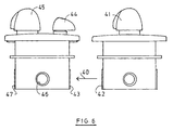
- connection block with two supply lines and at least one mixed water discharge 6 schematically shows another Embodiment.
- a connection block with two supply lines and at least one mixed water discharge 6 schematically shows another Embodiment.
- two in a concealed box Arranged terminal blocks available by a schematic connected by the arrow 40 line are.
- terminal block a thermostatic valve arranged, the target temperature with Can be set using a rotary knob 41.
- the four connections of the connection block one serves for the inlet of the cold water from the house installation and one for the inlet of warm water from the house installation. Another connection is not in operation, and the fourth Connection is used to deliver mixed water.
- This connection 42 is via an indicated line 40 with a connection 43 of a second connection block.
- connection block is a flow control valve operatively connected that can be operated with the aid of a rotary knob 44.
- a changeover valve is connected to the connection block can be operated with the help of a changeover button 45. It can switch between three outlets in the example shown.
- connection blocks can either be in a common Flush-mounted box or in two separate flush-mounted boxes be arranged. They can also be spatially different from each other be arranged separately.
- connection block is identical for all fittings, while the valve body on its the connection block facing side is designed so that all valve body together with the identical connection block are functional. Is on its opposite side the body of the valve to the increasing parts of the valve customized.
Landscapes
- Health & Medical Sciences (AREA)
- Life Sciences & Earth Sciences (AREA)
- Engineering & Computer Science (AREA)
- Hydrology & Water Resources (AREA)
- Public Health (AREA)
- Water Supply & Treatment (AREA)
- Valve Housings (AREA)
- Domestic Plumbing Installations (AREA)
- Quick-Acting Or Multi-Walled Pipe Joints (AREA)
- Orthopedics, Nursing, And Contraception (AREA)
- Multiple-Way Valves (AREA)
Abstract
Description
- Fig. 1
- eine Aufsicht auf einen Anschlussblock für das System nach der Erfindung;
- Fig. 2
- einen abgewinkelten Schnitt längs Linie II-II in Fig. 1;
- Fig. 3
- eine teilweise geschnittene Seitenansicht eines mit dem Anschlussblock zu verbindenden Duschventils;
- Fig. 4
- eine teilweise geschnittene Seitenansicht eines an dem Anschlussblock befestigten Thermostatventils mit einem Absperrventil;
- Fig. 5
- eine teilweise geschnittene Seitenansicht eines Wannenventils.
- Fig. 6
- eine schematische Ausführungsform mit zwei zusammen geschalteten Anschlussblöcken.
Claims (15)
- System von Sanitärarmaturen, mit1.1 einem für alle Sanitärarmaturen identischen Anschlussblock, der1.1.1 mindestens einen Anschluss (4) für eine Wasserzuleitung,1.1.2 mindestens einen Anschluss (4) für eine weiterführende Mischwasserleitung und1.1.3 eine Trennfläche (2) mit Durchgangsöffnungen (8) aufweist, die1.2 mit jeweils einem Anschluss (4) des Anschlussblocks in Verbindung stehen,1.3 einer Mehrzahl von unterschiedlichen Sanitärarmaturen, die1.3.1 eine Trennfläche mit Durchgangsöffnungen aufweisen und1.3.2 derart an dem Anschlussblock angebracht werden können, dass1.3.3 die Sanitärarmatur funktionsfähig ist.
- System nach Anspruch 1, bei dem die Sanitärarmaturen einen Armaturengrundkörper (11, 22, 32) aufweisen, der die Trennfläche und von dieser zu den Sanitärarmaturenteilen führende Kanäle (12) aufweist.
- System nach Anspruch 1 oder 2, bei dem der Armaturengrundkörper (11, 22, 32) Funktionsteile der Sanitärarmaturen aufweist.
- System nach einem der vorhergehenden Ansprüche, bei dem der Armaturengrundkörper (11, 22, 32) in vier verschiedenen Positionen mit dem Anschlussblock verbindbar ist.
- System nach Anspruch, bei dem die vier Positionen um 180 Grad versetzt sind.
- System nach einem der Ansprüche 2 bis 5, bei dem der Armaturengrundkörper (11, 22, 32) direkt an dem Anschlussblock angeschraubt werden kann.
- System nach einem der Ansprüche 2 bis 6, bei dem durch das Befestigen des Armaturengrundkörpers (11, 22, 32) an dem Anschlussblock gleichzeitig die Wasserverbindung herstellbar ist.
- System nach einem der vorhergehenden Ansprüche, bei dem alle Funktionsteile in dem Armaturengrundkörper (11, 22, 32) und/oder der Sanitärarmatur angeordnet sind.
- System nach einem der vorhergehenden Ansprüche, bei dem die Trennfläche (2) des Anschlussblocks eben ist.
- System nach einem der vorhergehenden Ansprüche, bei dem der Anschlussblock in seiner Trennfläche (2) mindestens ein Sackloch (9) aufweist.
- System nach einem der vorhergehenden Ansprüche, bei dem die Leitungsanschlüsse (4) des Anschlussblocks identisch ausgebildet sind.
- System nach einem der vorhergehenden Ansprüche, bei dem durch die Sanitärarmaturen zwei Leitungsanschlüsse (4) des Anschlussblocks miteinander verbindbar sind.
- System nach einem der vorhergehenden Ansprüche, bei dem der Armaturengrundkörper (11, 22, 32) Teile mehr als einer Sanitärarmatur aufnimmt.
- System nach einem der vorhergehenden Ansprüche, bei dem der Anschlussblock einen Anschluss für eine Zuleitung und drei Anschlüsse für weiterführende Leitungen aufweist.
- System nach einem der Ansprüche 1 bis 13, bei dem der Anschlussblock zwei Anschlüsse für Zuleitungen und zwei Anschlüsse für weiterführende Leitungen aufweist.
Priority Applications (1)
| Application Number | Priority Date | Filing Date | Title |
|---|---|---|---|
| DK99124280T DK1006242T3 (da) | 1998-12-05 | 1999-12-04 | System af sanitetsarmaturer |
Applications Claiming Priority (2)
| Application Number | Priority Date | Filing Date | Title |
|---|---|---|---|
| DE1998156155 DE19856155A1 (de) | 1998-12-05 | 1998-12-05 | System von Sanitärarmaturen |
| DE19856155 | 1998-12-05 |
Publications (3)
| Publication Number | Publication Date |
|---|---|
| EP1006242A2 true EP1006242A2 (de) | 2000-06-07 |
| EP1006242A3 EP1006242A3 (de) | 2001-03-14 |
| EP1006242B1 EP1006242B1 (de) | 2005-03-02 |
Family
ID=7890086
Family Applications (1)
| Application Number | Title | Priority Date | Filing Date |
|---|---|---|---|
| EP99124280A Revoked EP1006242B1 (de) | 1998-12-05 | 1999-12-04 | System von Sanitärarmaturen |
Country Status (6)
| Country | Link |
|---|---|
| US (1) | US6378911B1 (de) |
| EP (1) | EP1006242B1 (de) |
| AT (1) | ATE290135T1 (de) |
| DE (2) | DE19856155A1 (de) |
| DK (1) | DK1006242T3 (de) |
| ES (1) | ES2238807T3 (de) |
Cited By (6)
| Publication number | Priority date | Publication date | Assignee | Title |
|---|---|---|---|---|
| DE10233863A1 (de) * | 2002-07-19 | 2004-01-29 | Hansgrohe Ag | Anschlussblock für Sanitärarmaturen |
| EP1760205A1 (de) * | 2005-09-03 | 2007-03-07 | Kludi GmbH & Co. KG | Anschlussblock für eine Sanitärarmatur und System von Sanitärarmaturen |
| EP1775394A1 (de) * | 2005-10-12 | 2007-04-18 | Kludi GmbH & Co. KG | Anschlussblock für eine Sanitärarmatur |
| DE102011076210A1 (de) * | 2011-05-20 | 2012-11-22 | Hansgrohe Se | Sanitärarmatur |
| DE102013113591A1 (de) * | 2013-12-06 | 2015-06-11 | Kludi Gmbh & Co. Kg | Wasserschalteinheit |
| EP3144432B1 (de) * | 2015-09-21 | 2020-08-19 | Oras Oy | Bausatz für eine sanitäre unterputzarmatur |
Families Citing this family (13)
| Publication number | Priority date | Publication date | Assignee | Title |
|---|---|---|---|---|
| DE19953639A1 (de) * | 1999-11-09 | 2001-05-10 | Kludi Armaturen Scheffer Vertr | Einhebelmischer mit wechselbarer Kartusche |
| US20030140412A1 (en) * | 2003-03-05 | 2003-07-31 | Arthur Gabriele | Replaceable shower device |
| DE10342103B4 (de) * | 2003-09-10 | 2006-02-16 | Seemann Sub Gmbh & Co. Kg | Absperrventil für einen ortsbeweglichen Druckgasbehälter, insbesondere für eine Pressluftflasche für den Taucheinsatz |
| DE102008013736B4 (de) * | 2008-03-11 | 2017-07-06 | Ideal Standard International Nv | Einbaukasten zum variablen Einbau von Sanitärarmaturen |
| DE102008023671B4 (de) | 2008-05-15 | 2016-03-24 | Grohe Ag | Wandhalterung |
| DE102012203394B4 (de) | 2012-03-05 | 2017-11-02 | Hansgrohe Se | Anschlussblock für Sanitärarmaturen |
| US9182045B2 (en) | 2013-03-13 | 2015-11-10 | Kohler Co. | Concentric diverter cartridge |
| US9069359B2 (en) | 2013-03-13 | 2015-06-30 | Kohler Co. | Pressure balance unit |
| US9334971B2 (en) | 2013-03-13 | 2016-05-10 | Kohler Co. | Universal valve body |
| US9416884B2 (en) | 2013-03-13 | 2016-08-16 | Kohler Co. | Fluid control valve and assembly |
| US10724215B2 (en) | 2017-09-06 | 2020-07-28 | Kohler Co. | Faucet fixation system |
| MX2020004248A (es) * | 2017-10-23 | 2020-08-03 | As America Inc | Valvula de empalme universal. |
| DE102019203218A1 (de) * | 2019-03-08 | 2020-09-10 | Hansgrohe Se | Wandmontierbare sanitäre Leitungsanschlussvorrichtung mit integriertem Ventil |
Citations (1)
| Publication number | Priority date | Publication date | Assignee | Title |
|---|---|---|---|---|
| DE19622368A1 (de) | 1996-06-04 | 1997-12-11 | Hansa Metallwerke Ag | Mehrzahl von sanitären Mischarmaturen |
Family Cites Families (19)
| Publication number | Priority date | Publication date | Assignee | Title |
|---|---|---|---|---|
| US685876A (en) * | 1901-02-28 | 1901-11-05 | Shields Flexible Joints Company | Flexible-joint coupling. |
| US2898079A (en) * | 1953-08-05 | 1959-08-04 | Bowser Inc | Four-way valve |
| US3072148A (en) * | 1956-04-09 | 1963-01-08 | Carls William | Valve housing mount and manifold |
| US3176954A (en) * | 1961-04-13 | 1965-04-06 | Ross Operating Valve Co | Convertible valve assembly |
| FR2257846B1 (de) * | 1973-07-03 | 1976-05-28 | Legris France Sa | |
| IT8306978U1 (it) | 1983-04-22 | 1984-10-22 | Rapetti Rubinetterie | Rubinetto miscelatore a comando manuale costituito da elementi modulari intercambiabili |
| DE3519652C2 (de) | 1985-06-01 | 1997-12-18 | Grohe Armaturen Friedrich | Unterputzanschlußstück für Sanitärarmaturen |
| IT208850Z2 (it) | 1986-10-10 | 1988-05-28 | Galatron Srl | Elemento adattatore per il corpo ela valvola a cartuccia di rubinetti miscelatori per acqua calda e fredda. |
| IT1204669B (it) | 1987-05-29 | 1989-03-10 | Antonio Romanelli | Gruppo idrico da incasso per l'alimentazione di acqua ad articoli sanitari |
| EP0309397B2 (de) | 1987-09-09 | 1999-04-14 | Fides Treuhandgesellschaft | Sanitäre Wasseranschlussanordnung |
| DE3903997A1 (de) | 1989-02-10 | 1990-08-16 | Grohe Armaturen Friedrich | Mischventil fuer sanitaerarmaturen |
| US4938251A (en) * | 1989-07-11 | 1990-07-03 | Gilbarco Inc. | Universal hose adapter for gasoline pump |
| AU8635791A (en) * | 1990-09-05 | 1992-03-30 | Newmatic Controls Inc. | Modular pneumatic control systems |
| CH685205A5 (de) * | 1992-05-18 | 1995-04-28 | Fides Treuhand Gmbh | Anschlussvorrichtung für eine sanitäre Mischarmatur. |
| FI92862C (fi) | 1992-09-30 | 1995-01-10 | Oras Oy | Vesihanayhdistelmä |
| AT400165B (de) | 1993-02-16 | 1995-10-25 | Ideal Standard | Grundkörper für sanitäre armaturen |
| WO1996036829A1 (de) * | 1995-05-19 | 1996-11-21 | Bürkert Werke GmbH & Co. | Modularer ventilaufbau |
| DE19605328A1 (de) * | 1996-02-14 | 1997-08-21 | Grohe Kg Hans | Sanitärarmatur |
| US5964481A (en) * | 1998-07-10 | 1999-10-12 | Buch; Dana | Modular mounting apparatus for fluid control components |
-
1998
- 1998-12-05 DE DE1998156155 patent/DE19856155A1/de not_active Withdrawn
-
1999
- 1999-12-03 US US09/454,665 patent/US6378911B1/en not_active Expired - Fee Related
- 1999-12-04 ES ES99124280T patent/ES2238807T3/es not_active Expired - Lifetime
- 1999-12-04 DK DK99124280T patent/DK1006242T3/da active
- 1999-12-04 AT AT99124280T patent/ATE290135T1/de not_active IP Right Cessation
- 1999-12-04 EP EP99124280A patent/EP1006242B1/de not_active Revoked
- 1999-12-04 DE DE59911691T patent/DE59911691D1/de not_active Expired - Fee Related
Patent Citations (1)
| Publication number | Priority date | Publication date | Assignee | Title |
|---|---|---|---|---|
| DE19622368A1 (de) | 1996-06-04 | 1997-12-11 | Hansa Metallwerke Ag | Mehrzahl von sanitären Mischarmaturen |
Cited By (9)
| Publication number | Priority date | Publication date | Assignee | Title |
|---|---|---|---|---|
| DE10233863A1 (de) * | 2002-07-19 | 2004-01-29 | Hansgrohe Ag | Anschlussblock für Sanitärarmaturen |
| DE10233863B4 (de) * | 2002-07-19 | 2009-06-10 | Hansgrohe Ag | Anschlussblock für Sanitärarmaturen |
| EP1760205A1 (de) * | 2005-09-03 | 2007-03-07 | Kludi GmbH & Co. KG | Anschlussblock für eine Sanitärarmatur und System von Sanitärarmaturen |
| EP1775394A1 (de) * | 2005-10-12 | 2007-04-18 | Kludi GmbH & Co. KG | Anschlussblock für eine Sanitärarmatur |
| DE102011076210A1 (de) * | 2011-05-20 | 2012-11-22 | Hansgrohe Se | Sanitärarmatur |
| DE102011076210B4 (de) * | 2011-05-20 | 2017-03-16 | Hansgrohe Se | Befestigungsanordnung für zwei benachbarte Sanitärarmaturen |
| DE102013113591A1 (de) * | 2013-12-06 | 2015-06-11 | Kludi Gmbh & Co. Kg | Wasserschalteinheit |
| EP2889522A1 (de) * | 2013-12-06 | 2015-07-01 | Kludi GmbH & Co. KG | Wasserschalteinheit |
| EP3144432B1 (de) * | 2015-09-21 | 2020-08-19 | Oras Oy | Bausatz für eine sanitäre unterputzarmatur |
Also Published As
| Publication number | Publication date |
|---|---|
| DK1006242T3 (da) | 2005-06-20 |
| DE19856155A1 (de) | 2000-06-08 |
| EP1006242A3 (de) | 2001-03-14 |
| ATE290135T1 (de) | 2005-03-15 |
| EP1006242B1 (de) | 2005-03-02 |
| ES2238807T3 (es) | 2005-09-01 |
| US6378911B1 (en) | 2002-04-30 |
| DE59911691D1 (de) | 2005-04-07 |
Similar Documents
| Publication | Publication Date | Title |
|---|---|---|
| EP1006242B1 (de) | System von Sanitärarmaturen | |
| DE3043422A1 (de) | Verteiler, insbesondere fuer das wasser in heizanlagen | |
| AT409775B (de) | Mehrzahl von sanitären mischarmaturen | |
| AT396605B (de) | Unterputzanschlussstück für sanitärarmaturen | |
| DE102016000766B4 (de) | Sanitäres Auslaufstück, Sanitärarmatur und Verwendung eines Auslaufstücks | |
| DE102011008804B4 (de) | Sanitärarmatur | |
| DE3826064A1 (de) | Anschlussanordnung fuer eine sanitaere mischarmatur | |
| DE19954455A1 (de) | Stelleinheit zur Erzeugung variabler Ladungsbewegungen im Zylinder einer Kolbenbrennkraftmaschine | |
| EP0071729B1 (de) | Einloch-Mischbatterie | |
| EP0309397B1 (de) | Sanitäre Wasseranschlussanordnung | |
| DE3730375C2 (de) | ||
| EP0790448B1 (de) | Sanitärarmatur | |
| DE102005023757B4 (de) | Mischbatterie für Kalt- und Heißwasser | |
| DE102015012040A1 (de) | Ein Bausatz für eine sanitäre Unterputzarmatur mit einem Verbindungsbauteil und einer Ventilfunktionseinheit | |
| EP1435480B1 (de) | Sanitärarmatur | |
| EP1446534B1 (de) | Sanitärarmaturenblock | |
| EP1614944B1 (de) | Mehrwegemisch- oder verteilventil | |
| EP1390586B1 (de) | Sanitärarmaturenblock | |
| EP0855635B1 (de) | Sanitärarmatur | |
| DE19510345A1 (de) | Durchlauferhitzer | |
| DE2922580C2 (de) | Mischventil | |
| EP1656518A1 (de) | Modulares ventil- und verteilersystem | |
| DE10233863A1 (de) | Anschlussblock für Sanitärarmaturen | |
| DE29504852U1 (de) | Durchlauferhitzer | |
| DE3941106A1 (de) | Sanitaere mischbatterie fuer wandanschluss |
Legal Events
| Date | Code | Title | Description |
|---|---|---|---|
| PUAI | Public reference made under article 153(3) epc to a published international application that has entered the european phase |
Free format text: ORIGINAL CODE: 0009012 |
|
| AK | Designated contracting states |
Kind code of ref document: A2 Designated state(s): AT BE CH CY DE DK ES FI FR GB GR IE IT LI LU MC NL PT SE |
|
| AX | Request for extension of the european patent |
Free format text: AL;LT;LV;MK;RO;SI |
|
| PUAL | Search report despatched |
Free format text: ORIGINAL CODE: 0009013 |
|
| AK | Designated contracting states |
Kind code of ref document: A3 Designated state(s): AT BE CH CY DE DK ES FI FR GB GR IE IT LI LU MC NL PT SE |
|
| AX | Request for extension of the european patent |
Free format text: AL;LT;LV;MK;RO;SI |
|
| 17P | Request for examination filed |
Effective date: 20010421 |
|
| AKX | Designation fees paid |
Free format text: AT BE CH CY DE DK ES FI FR GB GR IE IT LI LU MC NL PT SE |
|
| AXX | Extension fees paid |
Free format text: SI PAYMENT 20010421 |
|
| 17Q | First examination report despatched |
Effective date: 20031008 |
|
| GRAP | Despatch of communication of intention to grant a patent |
Free format text: ORIGINAL CODE: EPIDOSNIGR1 |
|
| GRAS | Grant fee paid |
Free format text: ORIGINAL CODE: EPIDOSNIGR3 |
|
| GRAA | (expected) grant |
Free format text: ORIGINAL CODE: 0009210 |
|
| AK | Designated contracting states |
Kind code of ref document: B1 Designated state(s): AT BE CH CY DE DK ES FI FR GB GR IE IT LI LU MC NL PT SE |
|
| AX | Request for extension of the european patent |
Extension state: SI |
|
| PG25 | Lapsed in a contracting state [announced via postgrant information from national office to epo] |
Ref country code: NL Free format text: LAPSE BECAUSE OF FAILURE TO SUBMIT A TRANSLATION OF THE DESCRIPTION OR TO PAY THE FEE WITHIN THE PRESCRIBED TIME-LIMIT Effective date: 20050302 Ref country code: IE Free format text: LAPSE BECAUSE OF FAILURE TO SUBMIT A TRANSLATION OF THE DESCRIPTION OR TO PAY THE FEE WITHIN THE PRESCRIBED TIME-LIMIT Effective date: 20050302 Ref country code: FI Free format text: LAPSE BECAUSE OF FAILURE TO SUBMIT A TRANSLATION OF THE DESCRIPTION OR TO PAY THE FEE WITHIN THE PRESCRIBED TIME-LIMIT Effective date: 20050302 |
|
| REG | Reference to a national code |
Ref country code: GB Ref legal event code: FG4D Free format text: NOT ENGLISH |
|
| REG | Reference to a national code |
Ref country code: CH Ref legal event code: EP |
|
| REG | Reference to a national code |
Ref country code: CH Ref legal event code: NV Representative=s name: TROESCH SCHEIDEGGER WERNER AG |
|
| REG | Reference to a national code |
Ref country code: IE Ref legal event code: FG4D Free format text: GERMAN |
|
| REF | Corresponds to: |
Ref document number: 59911691 Country of ref document: DE Date of ref document: 20050407 Kind code of ref document: P |
|
| GBT | Gb: translation of ep patent filed (gb section 77(6)(a)/1977) |
Effective date: 20050404 |
|
| PG25 | Lapsed in a contracting state [announced via postgrant information from national office to epo] |
Ref country code: GR Free format text: LAPSE BECAUSE OF FAILURE TO SUBMIT A TRANSLATION OF THE DESCRIPTION OR TO PAY THE FEE WITHIN THE PRESCRIBED TIME-LIMIT Effective date: 20050602 |
|
| REG | Reference to a national code |
Ref country code: DK Ref legal event code: T3 |
|
| PG25 | Lapsed in a contracting state [announced via postgrant information from national office to epo] |
Ref country code: PT Free format text: LAPSE BECAUSE OF FAILURE TO SUBMIT A TRANSLATION OF THE DESCRIPTION OR TO PAY THE FEE WITHIN THE PRESCRIBED TIME-LIMIT Effective date: 20050817 |
|
| NLV1 | Nl: lapsed or annulled due to failure to fulfill the requirements of art. 29p and 29m of the patents act | ||
| REG | Reference to a national code |
Ref country code: ES Ref legal event code: FG2A Ref document number: 2238807 Country of ref document: ES Kind code of ref document: T3 |
|
| REG | Reference to a national code |
Ref country code: IE Ref legal event code: FD4D |
|
| PLBI | Opposition filed |
Free format text: ORIGINAL CODE: 0009260 |
|
| PG25 | Lapsed in a contracting state [announced via postgrant information from national office to epo] |
Ref country code: CY Free format text: LAPSE BECAUSE OF FAILURE TO SUBMIT A TRANSLATION OF THE DESCRIPTION OR TO PAY THE FEE WITHIN THE PRESCRIBED TIME-LIMIT Effective date: 20051204 Ref country code: AT Free format text: LAPSE BECAUSE OF NON-PAYMENT OF DUE FEES Effective date: 20051204 |
|
| PLBI | Opposition filed |
Free format text: ORIGINAL CODE: 0009260 |
|
| PGFP | Annual fee paid to national office [announced via postgrant information from national office to epo] |
Ref country code: GB Payment date: 20051220 Year of fee payment: 7 Ref country code: FR Payment date: 20051220 Year of fee payment: 7 |
|
| PGFP | Annual fee paid to national office [announced via postgrant information from national office to epo] |
Ref country code: DK Payment date: 20051223 Year of fee payment: 7 Ref country code: CH Payment date: 20051223 Year of fee payment: 7 |
|
| PLBI | Opposition filed |
Free format text: ORIGINAL CODE: 0009260 |
|
| PGFP | Annual fee paid to national office [announced via postgrant information from national office to epo] |
Ref country code: ES Payment date: 20051227 Year of fee payment: 7 |
|
| ET | Fr: translation filed | ||
| PG25 | Lapsed in a contracting state [announced via postgrant information from national office to epo] |
Ref country code: MC Free format text: LAPSE BECAUSE OF NON-PAYMENT OF DUE FEES Effective date: 20051231 Ref country code: LU Free format text: LAPSE BECAUSE OF NON-PAYMENT OF DUE FEES Effective date: 20051231 Ref country code: BE Free format text: LAPSE BECAUSE OF NON-PAYMENT OF DUE FEES Effective date: 20051231 |
|
| 26 | Opposition filed |
Opponent name: GROHE WATER TECHNOLOGY AG & CO. KG Effective date: 20051108 |
|
| PGFP | Annual fee paid to national office [announced via postgrant information from national office to epo] |
Ref country code: DE Payment date: 20060124 Year of fee payment: 7 |
|
| 26 | Opposition filed |
Opponent name: HEINRICH SCHULTE GMBH & CO. KG Effective date: 20051201 Opponent name: GROHE WATER TECHNOLOGY AG & CO. KG Effective date: 20051108 |
|
| PLAX | Notice of opposition and request to file observation + time limit sent |
Free format text: ORIGINAL CODE: EPIDOSNOBS2 |
|
| 26 | Opposition filed |
Opponent name: KLUDI GMBH & CO.KG Effective date: 20051201 Opponent name: HEINRICH SCHULTE GMBH & CO. KG Effective date: 20051201 Opponent name: GROHE WATER TECHNOLOGY AG & CO. KG Effective date: 20051108 |
|
| PLBB | Reply of patent proprietor to notice(s) of opposition received |
Free format text: ORIGINAL CODE: EPIDOSNOBS3 |
|
| PG25 | Lapsed in a contracting state [announced via postgrant information from national office to epo] |
Ref country code: LI Free format text: LAPSE BECAUSE OF NON-PAYMENT OF DUE FEES Effective date: 20061231 Ref country code: CH Free format text: LAPSE BECAUSE OF NON-PAYMENT OF DUE FEES Effective date: 20061231 |
|
| PGFP | Annual fee paid to national office [announced via postgrant information from national office to epo] |
Ref country code: IT Payment date: 20061231 Year of fee payment: 8 |
|
| PG25 | Lapsed in a contracting state [announced via postgrant information from national office to epo] |
Ref country code: DE Free format text: LAPSE BECAUSE OF NON-PAYMENT OF DUE FEES Effective date: 20070703 |
|
| RDAF | Communication despatched that patent is revoked |
Free format text: ORIGINAL CODE: EPIDOSNREV1 |
|
| REG | Reference to a national code |
Ref country code: DK Ref legal event code: EBP |
|
| REG | Reference to a national code |
Ref country code: CH Ref legal event code: PL |
|
| GBPC | Gb: european patent ceased through non-payment of renewal fee |
Effective date: 20061204 |
|
| REG | Reference to a national code |
Ref country code: FR Ref legal event code: ST Effective date: 20070831 |
|
| RDAG | Patent revoked |
Free format text: ORIGINAL CODE: 0009271 |
|
| STAA | Information on the status of an ep patent application or granted ep patent |
Free format text: STATUS: PATENT REVOKED |
|
| PG25 | Lapsed in a contracting state [announced via postgrant information from national office to epo] |
Ref country code: GB Free format text: LAPSE BECAUSE OF NON-PAYMENT OF DUE FEES Effective date: 20061204 |
|
| 27W | Patent revoked |
Effective date: 20070813 |
|
| BERE | Be: lapsed |
Owner name: HANSGROHE A.G. Effective date: 20051231 |
|
| PG25 | Lapsed in a contracting state [announced via postgrant information from national office to epo] |
Ref country code: SE Free format text: LAPSE BECAUSE OF FAILURE TO SUBMIT A TRANSLATION OF THE DESCRIPTION OR TO PAY THE FEE WITHIN THE PRESCRIBED TIME-LIMIT Effective date: 20050602 Ref country code: DK Free format text: LAPSE BECAUSE OF NON-PAYMENT OF DUE FEES Effective date: 20070102 |
|
| PG25 | Lapsed in a contracting state [announced via postgrant information from national office to epo] |
Ref country code: FR Free format text: LAPSE BECAUSE OF NON-PAYMENT OF DUE FEES Effective date: 20070102 |